door lock ISUZU TROOPER 1995 User Guide
[x] Cancel search | Manufacturer: ISUZU, Model Year: 1995, Model line: TROOPER, Model: ISUZU TROOPER 1995Pages: 1928
Page 1212 of 1928
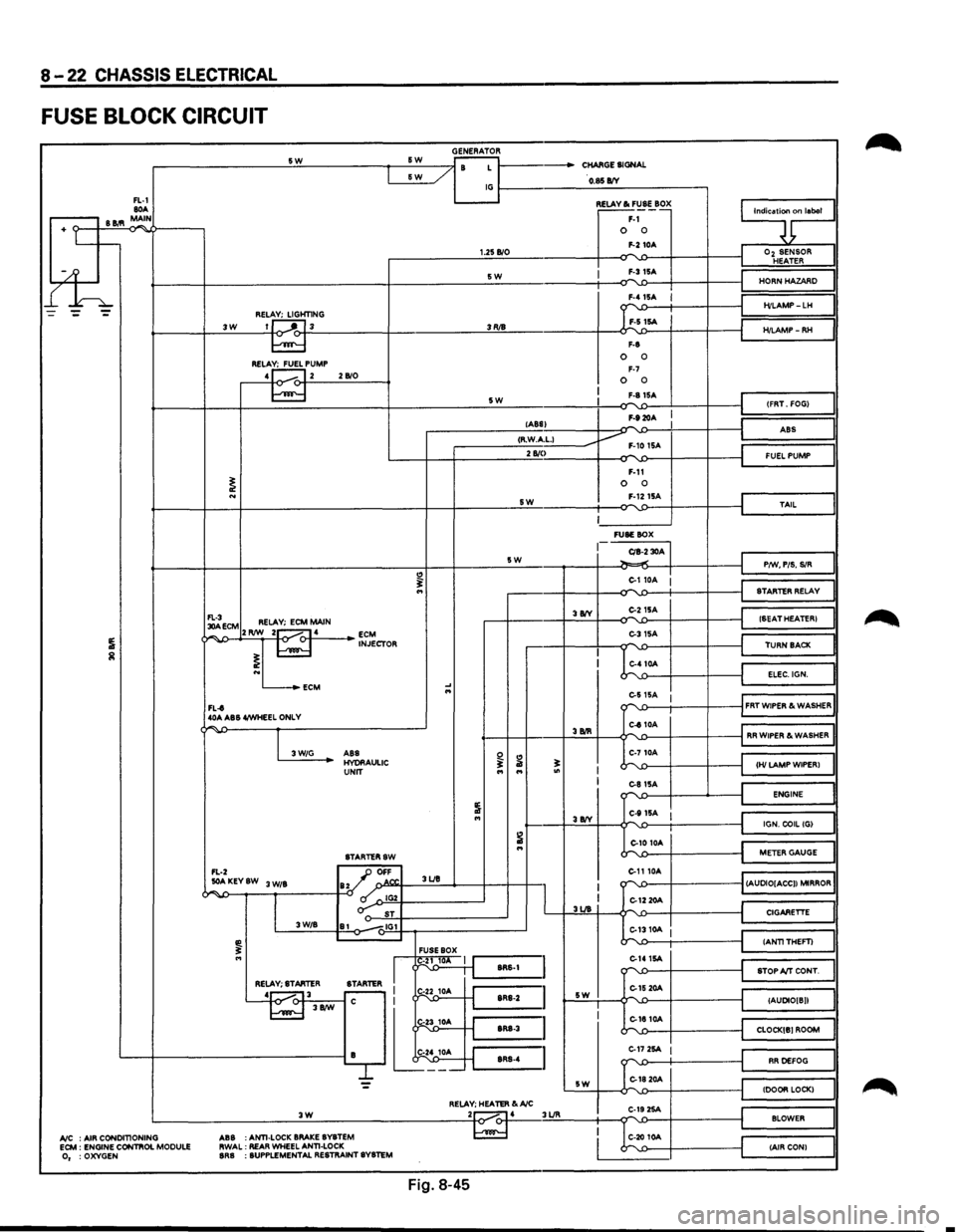
8-22 CHASSIS ELECTRICAL
FUSE BLOCK CIRCUIT
GENERATOR -------------------~s~w~------------~~s~w~--~~~~ r- / B L 1------CHARGE SIGNAL &W _/
FL-1 80A .-----, B 11.'1 MAIN
+ Lt--
l£h
~----/ IG~----------~O~.$~B/V~-----------,
3W REL~HT1NG 1J ---'"~L 3
RELA~PUMP 4 1...---. 12 2 B/0
1.25 B/0
SW
3RJ8
5W
~~~·~ F-1 0 0 F-2 10A
I F-315A
F-8
0 0 F-7 0 0 F-81SA
F-920A
9;nlaool
I
Oz SENSOR HEATER
HORN HAZARD
H/LAMP-LH
H/LAMP-RH
(FRT. FOG)
lABS) -I ABS
I ,--------__:<;;:R·.:.:W.::..Acc·L;;:-1 ____ ----Jv F-10 1SA 2 810
I
~ECM RELAY; ECM MAIN ¢~,...,..J>--+2'-'RIW~_::2~1-o.....-<:>-f-·4.:._ __ _. ~J~CTOR
L...-_.ECM
FL-t 40A ABS 4/WHEEL ONLY
"
.... ...
SW
5W
3 8IY
F-11 0 0 F-1215A
~------' FUSE BOX
CIB-2 30A ~.,.;
C-110A :
C-215A
C-31SA
C-410A
I
J
FUEL PUMP
TAIL
P/W, PIS. SIR
STARTER RELAY
(SEAT HEATER)
TURN BACK
ELEC.IGN.
e-s
15A 1 ""'-.0---t-----+----il FRT WIPER & WASHER
"""' -
I 3W/G
C-810A '---f-+----+.:3.:BIR::::..+---¢""''-£>---i-----f-----jl RR WIPER & WASHER
ABS HYORAULIC UNIT
STARTERSW
FL-2 _JJ OFF
~ ...
..:..AKEYSW 3 W/B ay ' o.N". 3UB
~~--~--~,~------~-0 ~~IG~2Y-----------~ o-: ST 3W/B 81 -.,IG1
FUSE BOX
I
I g1~ 1 J'-:::s:R:s-:1 =I RELAY; STARTER
STARTER I r-
L~---'~-j.t
I I 3UB
sw
C-710A
~';::--~--~-'---~~~HI~LA~M~P~W~IP~E~R~l~~ C-81SA ""'-'>--1---...__---i ENGINE
C-111SA I J~======~l IGN. COIL (G)
C-10 10A
C-1110A
k'-1:>----t----t
~==~I
METER GAUGE
""''-£>---f----------1 (AUDIO[ACC)) MIRROR
C-12 20A
::...1310A I
C-141SA -r"\'-1)----f----t
C-15 20A L,-.
CIGARETTE
(ANTITHEFT)
STOP A/T CONT.
(AUDIO[ B))
C-1810A """"-'-.0---f----------t_j CLOCK[B) ROOM
L---+------------------------iB lt~;_ ~=~~~:~:~::~~~: C-17 2SA I
G1820A
RR DEFOG
= sw (DOOR LOCK) RELAY; HEATER &A/C .:._ __________________ .:.:3~W'-'---------------------~2to~.....-4 3UR C-19 2SA ...... BLOWER
A/C : AIR CONDITIONING ECM : ENGINE CONTIIOL MODULE 0, :OXYGEN ABS
:ANTI-LOCK
BRAKE BYBTEM
RWAL: REAR WHEEL ANTI-LOCK BRB : SUPPLEMENTAL RESTRAINT SYSTEM
C-20 10A (AIR CON)
Fig. 8-45
•
Page 1214 of 1928
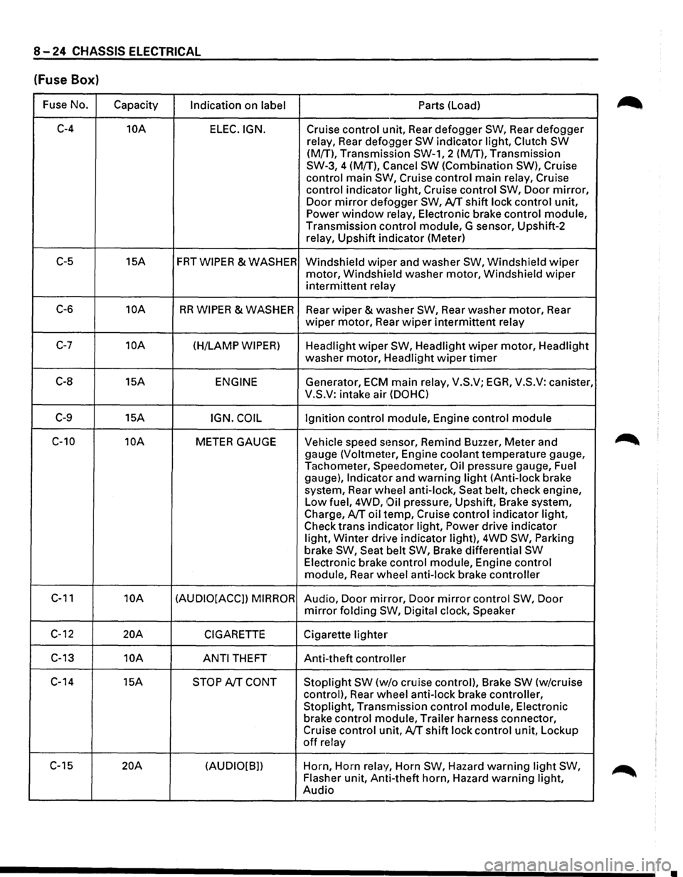
8-24 CHASSIS ELECTRICAL
(Fuse Box)
Fuse No.
Capacity Indication on label Parts (Load)
C-4 10A
ELEC.IGN. Cruise control unit, Rear defogger SW, Rear defogger
relay, Rear
defo9ger SW indicator light, Clutch SW
(M{T), Transmission SW-1, 2 (M!T), Transmission
SW-3, 4 (M{T), Cancel
SW (Combination SW), Cruise
control main
SW, Cruise control main relay, Cruise
control indicator light, Cruise control
SW, Door mirror,
Door mirror defogger SW, AfT shift lock control unit,
Power window relay, Electronic brake control module,
Transmission control module, G sensor, Upshift-2
relay, Upshift indicator (Meter)
C-5 15A FRTWIPER &WASHER
Windshield wipt~r and washer SW, Windshield wiper
motor, Windshit~ld washer motor, Windshield wiper
intermittent relay
C-6 10A RR WIPER & WASHER
Rear wiper & washer SW, Rear washer motor, Rear
wiper motor, Rear wiper intermittent relay
C-7 10A (H/LAMP WIPER) Headlight wiper SW, Headlight wiper motor, Headlight
washer motor, Headlight
wiper timer
C-8 15A ENGINE Generator, ECM main relay, V.S.V; EGA, V.S.V: canister,
V.S.V: intake air
(DOHC)
C-9 15A IGN. COIL Ignition control module, Engine control module
C-10 10A METER GAUGE Vehicle speed stmsor, Remind Buzzer, Meter and
gauge
(Voltmeter, Engine coolant temperature gauge,
Tachometer, Speedometer,
Oil pressure gauge, Fuel
gauge),
Indicator and warning light (Anti-lock brake
system, Rear wheel anti-lock, Seat belt, check engine,
Low fuel, 4WD,
Oil pressure, Upshift, Brake system,
Charge,
AfT oil temp, Cruise control indicator light,
Check trans indicator light,
Power drive indicator
light,
Winter drive indicator light), 4WD SW, Parking
brake SW, Seat belt SW, Brake differential SW
Electronic brake control module, Engine control
module, Rear wheel anti-lock brake controller
C-11 10A (AUDIO[ACCJ) MIRROR Audio, Door mirror, Door mirror control SW, Door
mirror folding SW, Digital clock, Speaker
C-12 20A CIGARETTE Cigarette lighter
C-13 10A
ANTI THEFT Anti-theft controller
C-14 15A
STOP AfT CONT Stoplight SW (w/o cruise control), Brake SW (w/cruise
control), Rear wheel anti-lock brake controller,
Stoplight, Transmission control module, Electronic
brake control module, Trailer harness connector,
Cruise control unit,
AfT shift lock control unit, Lockup
off relay
C-15
20A (AUDIO[B]) Horn,
Horn relay, Horn SW, Hazard warning light SW,
Flasher unit, Anti-theft horn, Hazard warning light,
Audio
•
Page 1215 of 1928
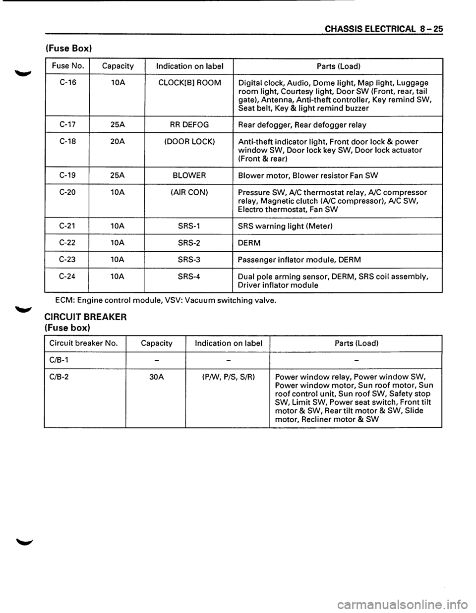
CHASSIS ELECTRICAL 8-25
(fuse Box)
Fuse No.
Capacity Indication on label Parts
(Load)
C-16
10A
CLOCK[B] ROOM Digital clock, Audio, Dome light, Map light, Luggage
room light, Courtesy light, Door SW (Front, rear, tail
gate), Antenna, Anti-theft controller, Key remind SW,
Seat belt, Key & light remind buzzer
C-17 25A RR DEFOG Rear defogger, Rear defogger relay
C-18 20A (DOOR LOCK) Anti-theft indicator light, Front door lock & power
window SW, Door lock key SW, Door lock actuator
(Front
& rear)
C-19 25A BLOWER Blower motor, Blower resistor Fan SW
C-20 10A (AIR CON) Pressure SW, A/C thermostat relay, A/C compressor
relay, Magnetic clutch
(A/C compressor), A/C SW,
Electro thermostat, Fan SW
C-21 10A SRS-1 SRS warning light (Meter)
C-22 10A SRS-2 DERM
C-23
10A SRS-3 Passenger inflator module, DERM
C-24
10A SRS-4 Dual pole arming sensor, DERM, SRS coil assembly,
Driver inflator module
ECM: Engine control module, VSV: Vacuum switching valve.
CIRCUIT BREAKER
(fuse box)
Circuit breaker No.
C/B-1
C/B-2
Capacity
-
30A
Indication on label
-
(P/W, P/S, S/R)
Parts (Load)
-
Power window relay, Power window SW,
Power window motor, Sun roof motor, Sun
roof control unit, Sun roof SW, Safety stop
SW, Limit SW, Power seat switch, Front tilt
motor & SW, Rear tilt motor & SW, Slide
motor, Recliner
motor & SW
Page 1219 of 1928
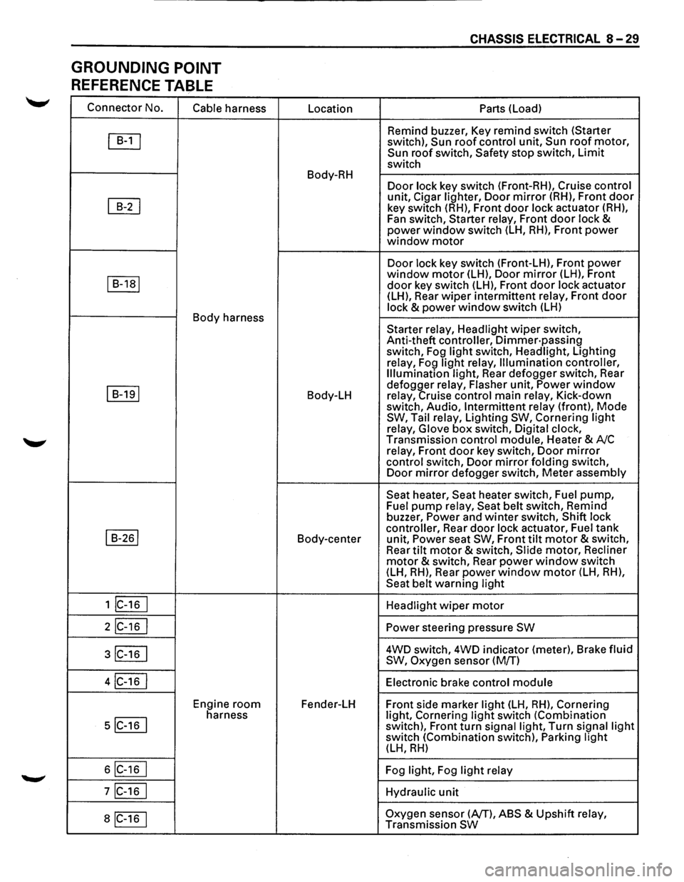
GROUNDING POINT
REFERENCE TABLE
Connector No.
Cable harness
~
~
I B-1a1
Body harness
I B-191
I B-261
1 lc-16 I
2IC-16 I
3IC-16 I
4IC-16 I
Engine room
5IC-16 I
harness
6IC-16 I
7IC-16 I
aiC-16 1
Location
Body-RH
Body-LH
Body-center
Fender-LH
CHASSIS ElECTRICAL 8-29
Parts (Load)
Remind buzzer, Key remind switch (Starter
switch),
Sun roof control unit, Sun roof motor, Sun roof switch, Safety stop switch, Limit
switch
Door lock key switch (Front-RH), Cruise control
unit, Cigar lighter, Door mirror (RH), Front door
key switch (RH), Front door lock actuator (RH),
Fan switch, Starter relay, Front
door lock & power window switch (LH, RH), Front power window motor
Door lock key switch (Front-LH), Front power window motor (LH), Door mirror (LH), Front
door key switch (LH), Front door lock actuator
(LH), Rear wiper intermittent relay, Front door
lock & power window switch (LH)
Starter relay, Headlight
wiper switch,
Anti-theft controller,
Dimmer·passing switch, Fog light switch, Headlight, Lighting
relay, Fog
light relay, Illumination controller,
Illumination light, Rear defogger switch, Rear
defogger relay, Flasher unit,
Power window relay, Cruise control main relay, Kick-down
switch, Audio, Intermittent relay (front), Mode SW, Tail relay, Lighting SW, Cornering light
relay, Glove box switch, Digital clock,
Transmission control module, Heater & A/C
relay, Front
door key switch, Door mirror
control switch, Door mirror folding switch,
Door mirror defogger switch, Meter assembly
Seat heater, Seat heater switch, Fuel pump, Fuel pump relay, Seat belt switch, Remind
buzzer, Power and winter switch, Shift lock
controller, Rear
door lock actuator, Fuel tank
unit, Power seat SW, Front tilt motor & switch,
Rear tilt motor & switch, Slide motor, Recliner
motor & switch, Rear power window switch
(LH, RH), Rear power window motor (LH, RH),
Seat belt warning light
Headlight
wiper motor
Power steering pressure SW
4WD switch, 4WD indicator (meter), Brake fluid
SW, Oxygen sensor (M/T)
Electronic brake control
module
Front side marker light (LH, RH), Cornering
light, Cornering light switch (Combination
switch), Front turn signal light, Turn signal light switch (Combination switch), Parking light (LH, RH)
Fog light, Fog light relay
Hydraulic
unit
Oxygen sensor (AfT), ABS & Upshift relay,
Transmission SW
Page 1326 of 1928
8 -136 CHASSIS ELECTRICAL
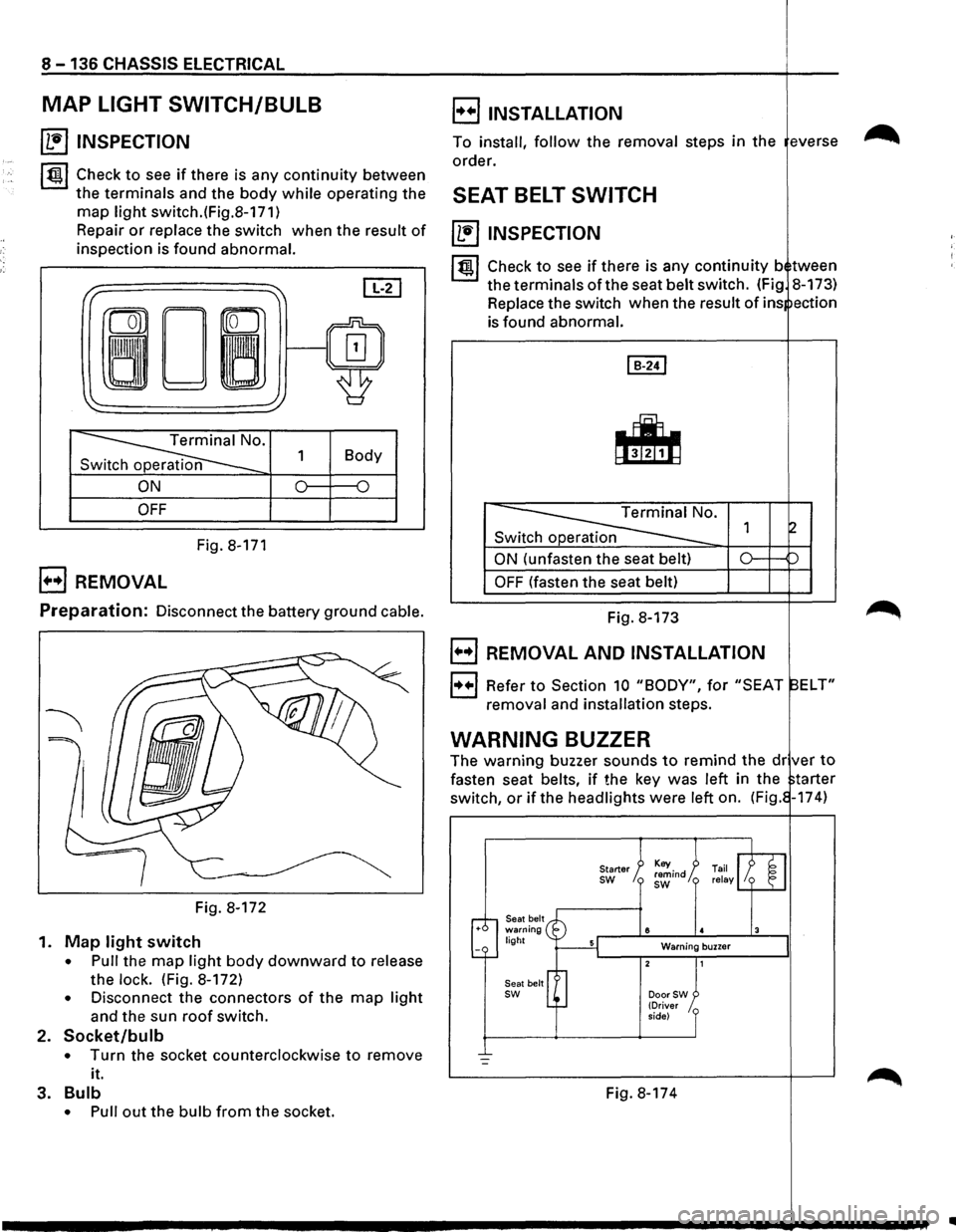
MAP LIGHT SWITCH/BULB
~ INSPECTION
~~~ Check to see if there is any continuity between
the terminals and the body while operating the
map light switch.(Fig.8-171)
Repair
or replace the switch when the result of
inspection is found abnormal.
I" ~ [IT]
ron
0~/~ ~
'
~· 1 Body
n
ON 0 {)
OFF
Fig. 8-171
B REMOVAL
E) INSTALLATION
To install, follow the removal steps in the everse
order.
SEAT BELT SWITCH
~ INSPECTION
I~ l Check to see if there is any continuity b tween
the terminals of the seat belt switch. (Fig 8-173)
Replace the switch when the
result of ins ection
is found abnormal.
Switch operation
ON (unfasten the seat belt)
OFF (fasten the seat belt)
Preparation: Disconnect the battery ground cable. Fig. 8-173
Fig. 8-172
1.
Map light switch
• Pull the map light body downward to release
the
lock. (Fig. 8-172)
• Disconnect the connectors of the map light
and the sun roof switch.
2. Socket/bulb
• Turn the socket counterclockwise to remove
it.
3.
Bulb
• Pull out the bulb from the socket.
B REMOVAL AND INSTALLATION
1++1 Refer to Section 10 "BODY", for "SEAT ELT"
removal and installation steps.
WARNING BUZZER
The warning buzzer sounds to remind the dr ver to
fasten seat belts, if the key was left in the tarter
switch,
or if the headlights were left on. (Fig. -174)
Seat belt warning light
Seat belt
sw
Starter sw
8
Warning buzzer
DoorSW (Driver
side)
Fig. 8-174
..
Page 1332 of 1928
8-142 CHASSIS ELECTRICAL
POWER DOOR LOCK
GENERAL DESCRIPTION
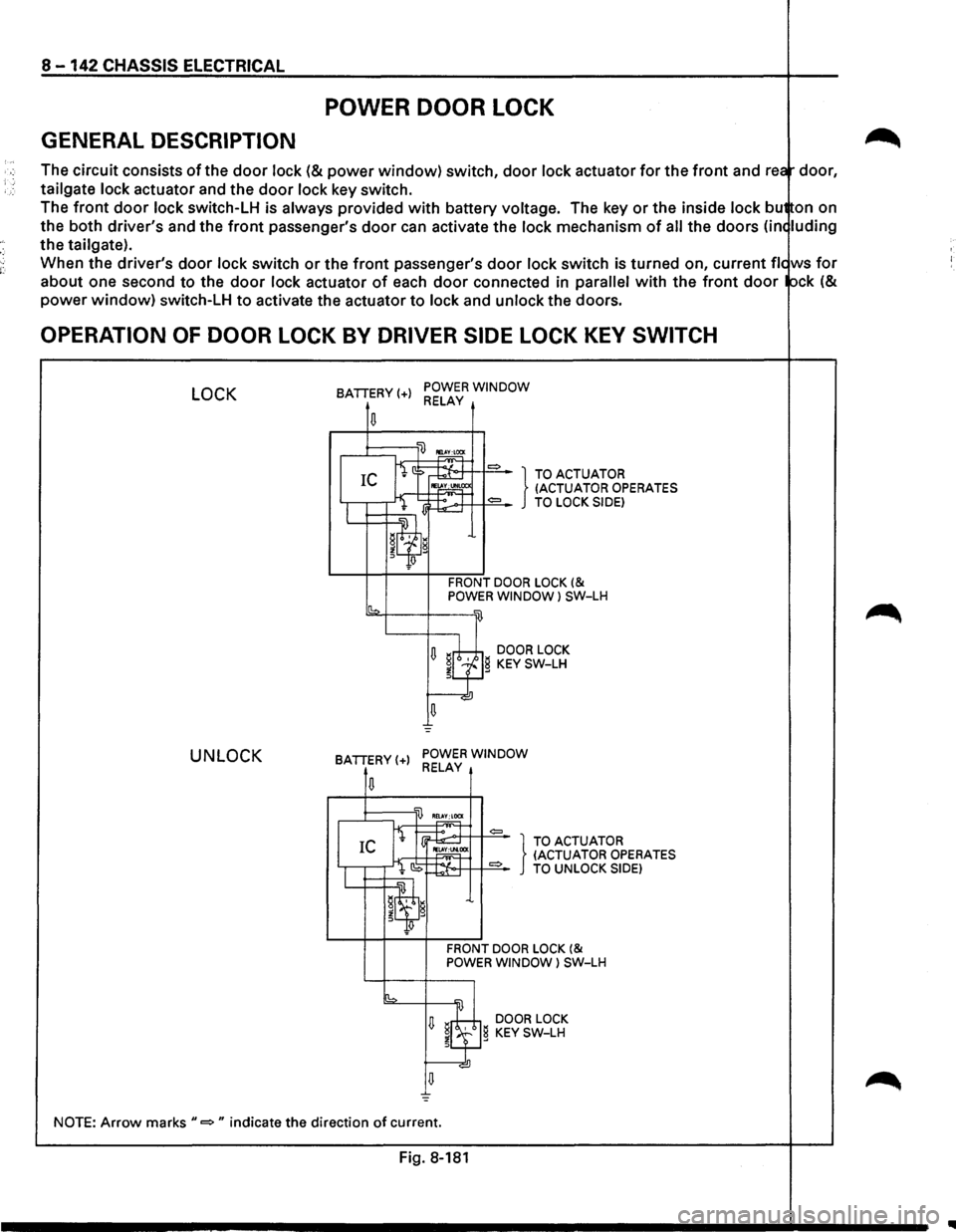
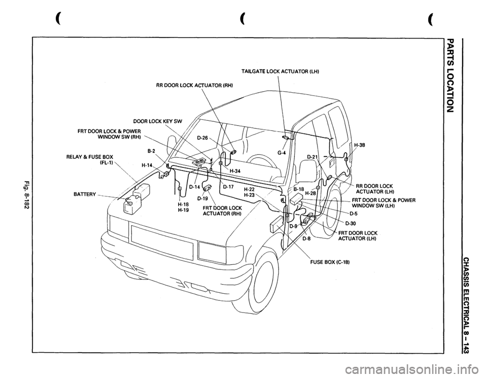
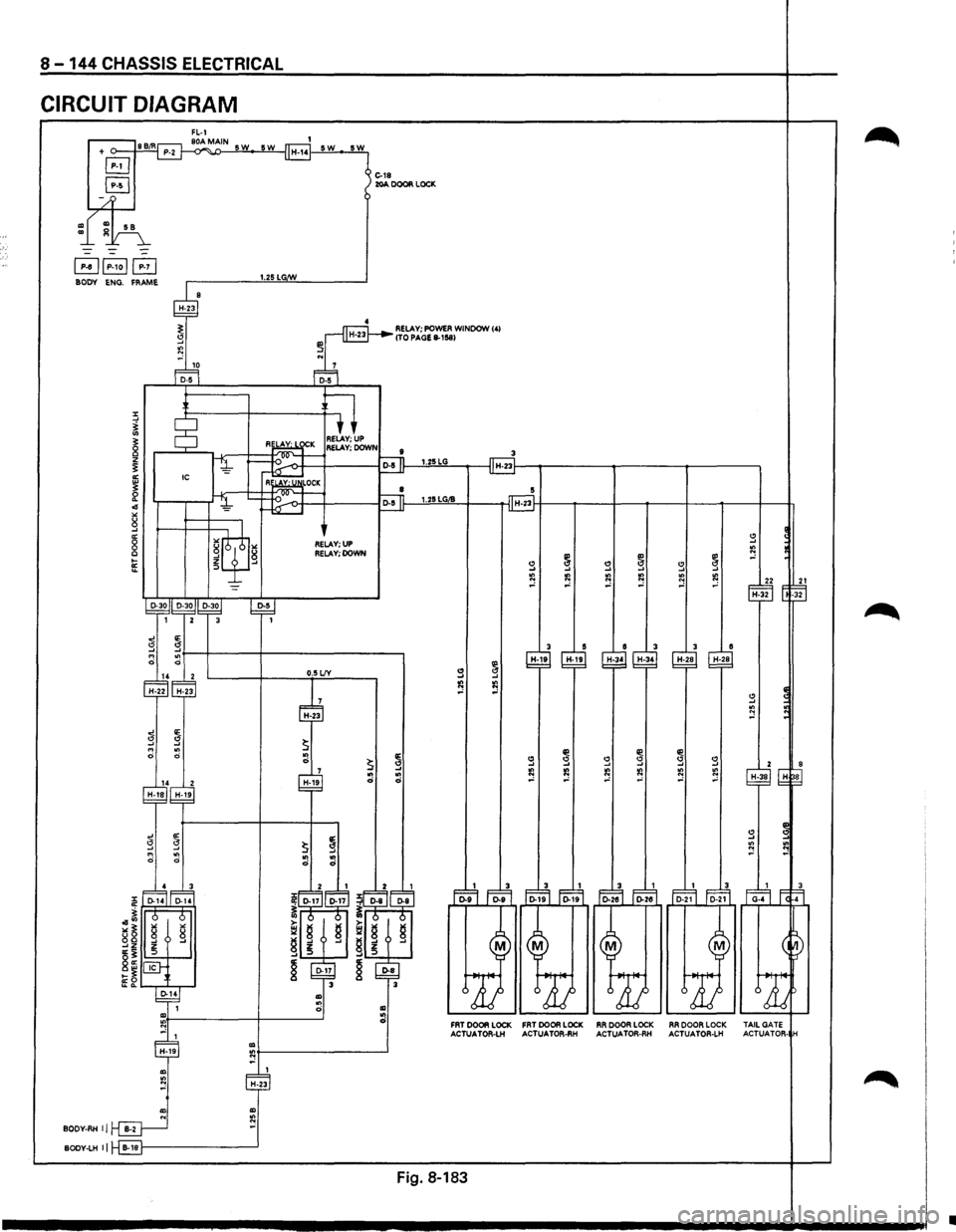
The circuit consists of the door lock (& power window) switch, door lock actuator for the front and rea door,
tailgate
lock actuator and the door lock key switch.
The
front door lock switch-LH is always provided with battery voltage. The key or the inside lock bu on on
the both driver's and the
front passenger's door can activate the lock mechanism of all the doors (in< luding
the tailgate).
When the driver's
door lock switch or the front passenger's door lock switch is turned on, current fie ws for
about one second to the door lock actuator of each door connected in parallel with the front door ock (&
power window) switch-LH to activate the actuator to lock and unlock the doors.
OPERATION OF DOOR LOCK BY DRIVER SIDE LOCK KEY SWITCH
LOCK
UNLOCK
BATTERY(+) POWER WINDOW RELAY
.....-1::::::;---'li) ~
fi ::> ~ = } TO ACTUATOR IC IE~CC (ACTUATOR OPERATES
I l lj~:.-.>+T++==-TO LOCK SIDE)
W=~~~~'l g
Jlf!
FRONT DOOR LOCK (& POWER WINDOW l SW-LH
sb2-f---+---w
U ~rh;±,i DOOR LOCK ~LfJg KEY SW-LH
u =
BATTERY(+) POWER WINDOW RELAY
,..,~T =
I IEl.
CS ~:t-o·++ 1+==-TO UNLOCK SIDE)
IL...t=:t=~~w.~ g
~q;J
FRONT DOOR LOCK (& POWER WINDOW) SW-LH
[b =
U ~8 DOOR LOCK
~l.f} KEY SW-LH
NOTE: Arrow marks"=" indicate the direction of current.
Fig. 8-181
IIIII
Page 1333 of 1928
"T1 !0 (X) I ... (X) N
(
RR
DOOR
LOCK
ACTUATOR
(RHI
DOOR
LOCK
KEY
SW
"-
FRT
DOOR
LOCK
& POWER
WINDOW SW
(RHI
RELAY
& FUSE
BOX (FL-11~
BATTERY
' ,,
( TAILGATE
LOCK
ACTUATOR
(LHI
RR
DOOR
LOCK
ACTUATOR
(LHI
h.=
I //If/:
I
FRT
DOOR
LOCK
& POWER
WINDOW
SW
(LHI
FRT
DOOR
LOCK
ACTUATOR
(LHI
FUSE
BOX
(C-181
(
~ ~ r-0 n ~ 0
2
(") J: )> en
en (i) m rm ~ :a g reo I ...a t
Page 1334 of 1928
8 -144 CHASSIS ELECTRICAL
CIRCUIT DIAGRAM
FL-1 86/R 80AMAIN SW 5W + o---+=-=-4 P-2 ~
GJ
GJ
/
1 H-14 SW
~~P-1ol~ BODY ENG. FRAME 1.25 LG/W
5W
1 C-18 J 20A DOOR LOCK
4 RELAY; POWER WINDOW 141 ITO PAGE 8-1!58)
...
r---D~D~~~1o~------------~~5~7-----,
§*f-----+------+--.51
RE' AY· I I'V'K RELAY; UP 1__;;=.l...v----J--·m~;:;:::::I--·~RELAY; DOWN I ~ ~ ~ 1.25LG IC H-23f----.----------------t--------~
R~LOCK 8 5 ~--r-_)~~i_~t~~~~l~~o~t~--~----~ID-si~~~1-~25~LG~~~~--H~~--~----+---~---4----~--~--~
~!
-
RELAY; UP RELAY; DOWN
D-30JI D-30/1 D-30j ~ 1 2
0 14 2 H-22 H-23
14 2
H-18 H-19
"' BODY-RHij~
3 1
0.5 L!Y
H-19
"' tQ~------------~
"' H-23
"' "' N "' BODY-LH II B-181---------------_J
22 21 H-32 0 -32
3 5 e 3 3 e H-19 H-19
H-34 H-34 H-28 H-28
" .... IQ ~ -' s "' ~ ::!
~ ~ II! s s g s 2
~ IQ
IQ ~ ~ "' IQ H-38 ~ N -' -' -' -'
s ~
"' ;, N ::! "'
Fo.~ Fo-~ Fo-i'f1 Fo-~ ~~ Fo-~ Fo-~ ~2~ Faf1 f. r.1
M M
FAT DOOR LOCK FAT DOOR LOCK ACTUATOA-LH ACTUA TOR-AH
Fig. 8-183
M
ARDOORLOCK ACTUATOR-RH
M
RADOOALOCK ACTUATOA-LH TAILGATE
ACTUATOR· H
•
Page 1336 of 1928
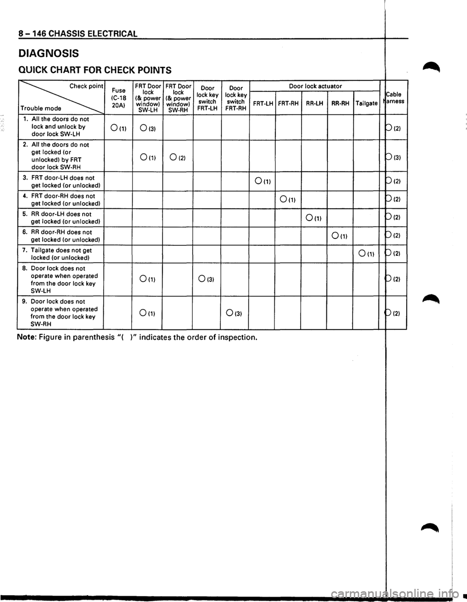
8 -146 CHASSIS ELECTRICAL
DIAGNOSIS
QUICK CHART FOR CHECK POINTS ~
~
Fuse FRT Door FRT Door
Door Door Door
lock actuator
lock lock
lock key lock key
Cable IC-18 I& power I& power 20AI window)
window) switch switch FRT-LH FRT-RH RR-LH RR-RH Tailgate
arness
T SW-LH SW-RH FRT-LH FRT-RH
1. All the doors do not
lock and unlock by
door lock SW-LH 0(1) 0131
P121
2. All the doors do not
get locked (or
0(1) 0121 Pl31 unlocked) by FRT door lock SW-RH
3. FRT door-LH does not 0(1) P121 get locked {or unlocked)
4. FRT door-RH does not 0111 P121 get
locked (or unlocked)
5. RR door-LH does not 0(1) P121 get locked (or unlocked)
6. RR door-RH does not 0111 P121 get
locked (or unlocked)
7. Tailgate does
not get 0111 P121 locked (or unlocked)
8. Door lock does not
operate when operated 0111 0131 p(2) from the door lock key SW-LH
9. Door lock does not ~ operate when operated Om 0131 P121 from the door lock key SW-RH
Note: Figure in parenthesis "( )" indicates the order of inspection.
~
•
Page 1337 of 1928
•
•
•
•
•
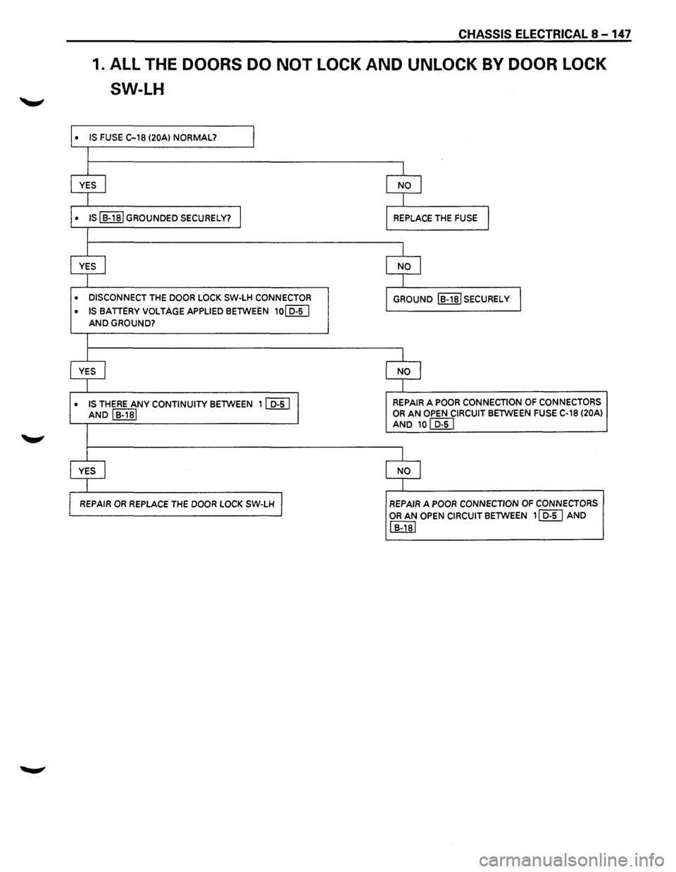
CHASSIS ELECTRICAL 8-147
1. ALL THE DOORS DO NOT LOCK AND UNLOCK BY DOOR LOCK
SW-LH
IS FUSE C-18 (20Al NORMAL? I
I
YES I NO I
I
IS I
B-181 GROUNDED SECURELY? I REPLACE THE FUSE I
I
YES
j NO I
l
DISCONNECT THE DOOR LOCK SW-LH CONNECTOR
GROUND IB-18ISECURELY
IS
BATTERY VOLTAGE APPLIED BETWEEN 10~
AND GROUND?
l
YES I NO I
l
IS THERE ANY CONTINUITY BETWEEN 11 D-5 I I REPAIR A POOR CONNECTION OF CONNECTORS
AND I B-181 OR AN OPEN CIRCUIT BETWEEN FUSE C-18 (20A)
AND 10 I D-51
I
YES I NO I
I
REPAIR
OR REPLACE THE DOOR LOCK SW-LH J REPAIR A POOR CONNECTION OF CONNECTORS
OR AN OPEN CIRCUIT BETWEEN 11 D-5 I AND
I B-181