transmission fluid ISUZU TROOPER 1995 Service Manual
[x] Cancel search | Manufacturer: ISUZU, Model Year: 1995, Model line: TROOPER, Model: ISUZU TROOPER 1995Pages: 1928
Page 1072 of 1928
7 A-200 AUTOMATIC TRANSMISSION (4L30-E)
l•!•l REASSEMBLY
11. Second clutch drum
10. Piston (Fig. 7A-78)
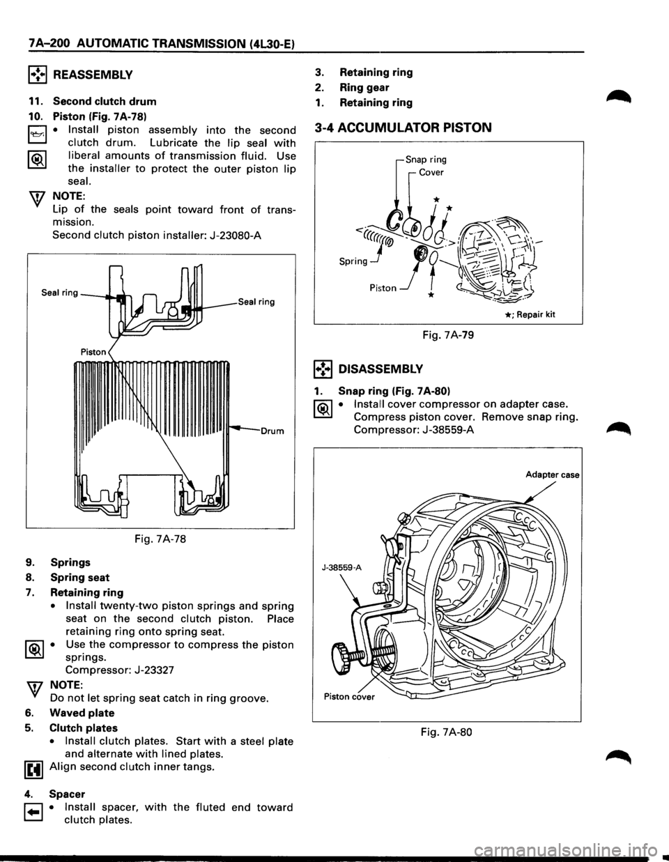
0 • Install piston assembly into the second
t..::::::.:J clutch drum. Lubricate the lip seal with
1®..1 liberal amounts of transmission fluid. Use
the installer to protect the outer piston lip
seal.
W NOTE:
Lip of the seals point toward front of trans
mission.
Second clutch piston installer: J-23080-A
Seal ring
3. Retaining ring
2. Ring gear
1. Retaining ring
3-4 ACCUMULATOR PISTON
,Snap ring
Cover
* *
<·-' ~·· ··~
Spring Jr-J
1
t -;;~~H -~, ~:·.-... , ' ~ '-'FJ:
Pi!;ton * ~~+_z.~~
*;Repair kit
Fig. 7A-79
1•!•1 DISASSEMBLY
1. Snap ring (Fig. 7 A-80)
l?.i\1 • Install! cover compressor on adapter case.
~ Compress piston cover. Remove snap ring.
Drum Compressor: J-38559-A
Fig. 7A-78
9. Springs
8. Spring seat
7. Retaining ring
• Install twenty-two piston springs and spring
seat on the second clutch piston. Place
retaining ring onto spring seat.
1 ®..I • Use the compressor to compress the piston
springs.
Compressor: J-23327
w NOTE:
Do not let spring seat catch in ring groove.
6. Waved plate
5. Clutch plates
• Install clutch plates. Start with a steel plate
and alternate with lined plates.
IEtl Align second clutch inner tangs.
4. Spacer
r::1 • Install spacer, with the fluted end toward
t.:=.l clutch plates.
Adapter case
Fig. 7A-80
•
Page 1086 of 1928
7A-214 AUTOMATIC TRANSMISSION (4L30-E)
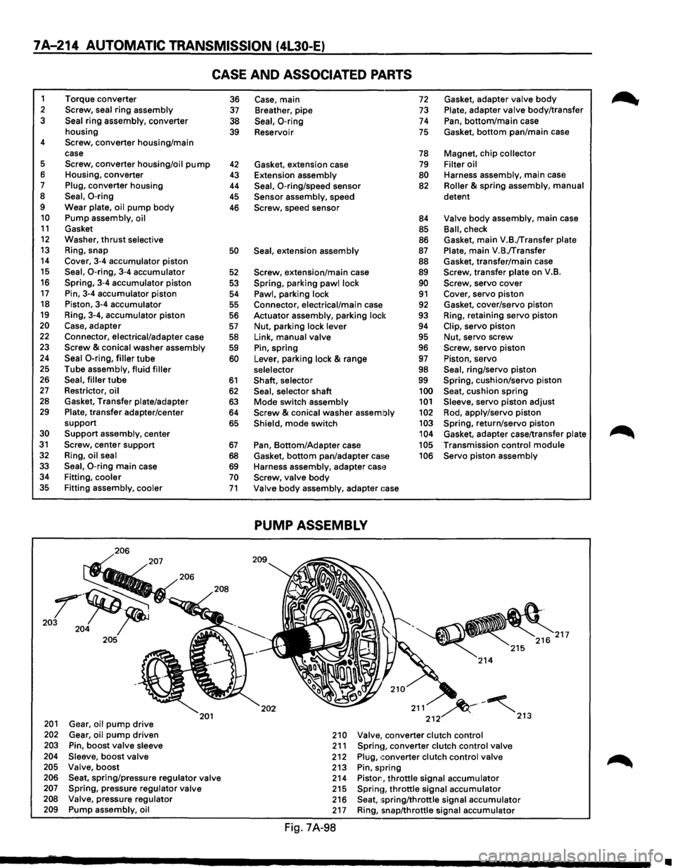
CASE AND ASSOCIATED PARTS
1 Torque converter 2 Screw, seal ring assembly 3 Seal ring assembly, converter
housing
4 Screw, converter housing/main
case
5 Screw, converter housing/oil pump 6 Housing, converter 7 Plug, converter housing 8 Seal, 0-ring 9 Wear plate, oil pump body 10 Pump assembly, oil 11 Gasket 12 Washer, thrust selective 13 Ring, snap 14 Cover, 3-4 accumulator piston 15 Seal, 0-ring, 3-4 accumulator 16 Spring, 3-4 accumulator piston 17 Pin, 3-4 accumulator piston 18 Piston, 3-4 accumulator 19 Ring, 3-4, accumulator piston 20 Case, adapter 22 Connector, electrical/adapter case 23 Screw & conical washer assembly 24 Seal 0-ring, filler tube 25 Tube assembly, fluid filler 26 Seal, filler tube 27 Restrictor, oil 28 Gasket, Transfer plate/adapter 29 Plate, transfer adapter/center
support
30 Support assembly, center 31 Screw, center support 32 Ring, oil seal
33 Seal, 0-ring main case 34 Fitting, cooler 35 Fitting assembly, cooler
206
201 Gear, oil pump drive 202 Gear, oil pump driven 203 Pin, boost valve sleeve 204 Sleeve, boost valve 205 Valve, boost
201
206 Seat, spring/pressure regulator valve 207 Spring, pressure regulator valve 208 Valve, pressure regulator 209 Pump assembly, oil
36 37
38
39
42 43
44
45
46
50
52
53
54
55
56
57
58 59
60
61
62 63 64
65
67
68 69 70 71
Case, main 72 Gasket, adapter valve body
Breather, pipe 73 Plate, adapter valve body/transfer
Seal, 0-ring 74 Pan, bottom/main case
Reservoir
75 Gasket, bottom pan/main case
78 Magnet, chip collector
Gasket, extension case
79 Filter oil
Extension assembly
80 Harness assembly, main case
Seal, 0-ring/speed sensor 82 Roller & spring assembly, manual
Sensor assembly, speed detent Screw, speed
sensor 84 Valve body assembly, main case
85 Ball, check
86 Gasket, main V.B./Transfer plate
Seal, extension assembly 87 Plate, main V.B./Transfer
88 Gasket, transfer/main case
Screw, extension/main case 89 Screw, transfer plate on V.B.
Spring, parking pawl lock 90 Screw, servo cover
Pawl, parking lock 91 Cover, servo piston Connector, electrical/main case 92 Gasket, cover/servo piston
Actuator assembly, parking lock
93 Ring, retaining servo piston
Nut, parking lock lever 94 Clip, servo piston
Link, manual valve 95 Nut, servo screw
Pin, spring 96 Screw, servo piston
Lever, parking lock
& range 97 Piston, servo
selelector 98 Seal, ring/servo piston
Shaft, selector 99 Spring, cushion/servo piston
Seal, selector shaft 100 Seat, cushion spring
Mode switch assembly 101 Sleeve, servo piston adjust
Screw & conical washer assembly 102 Rod, apply/servo piston
Shield, mode switch 103 Spring, return/servo piston 104 Gasket, adapter case/transfer plate
Pan, Bottom/Adapter case 105 Transmission control module
Gasket,
bottom pan/adapter ca!~e 106 Servo piston assembly
Harness assembly, adapter
cas'~ Screw, valve body
Valve body assembly, adapter ~:ase
PUMP ASSEMBLY
202 211 ~-~ 212 . 213
210 Valve, converter clutch control 211 Sprinn, converter clutch control valve 212 Plug, converter clutch control valve 213 Pin, spring 214 Piston, throttle signal accumulator 215 Sprinn, throttle signal accumulator 216 Seat, 1;pring/throttle signal accumulator 217 Ring, snap/throttle signal accumulator
Fig. 7A-98
~
•
Page 1161 of 1928
TRANSFER CASE 70-3
ON-VEHICLE SERVICE
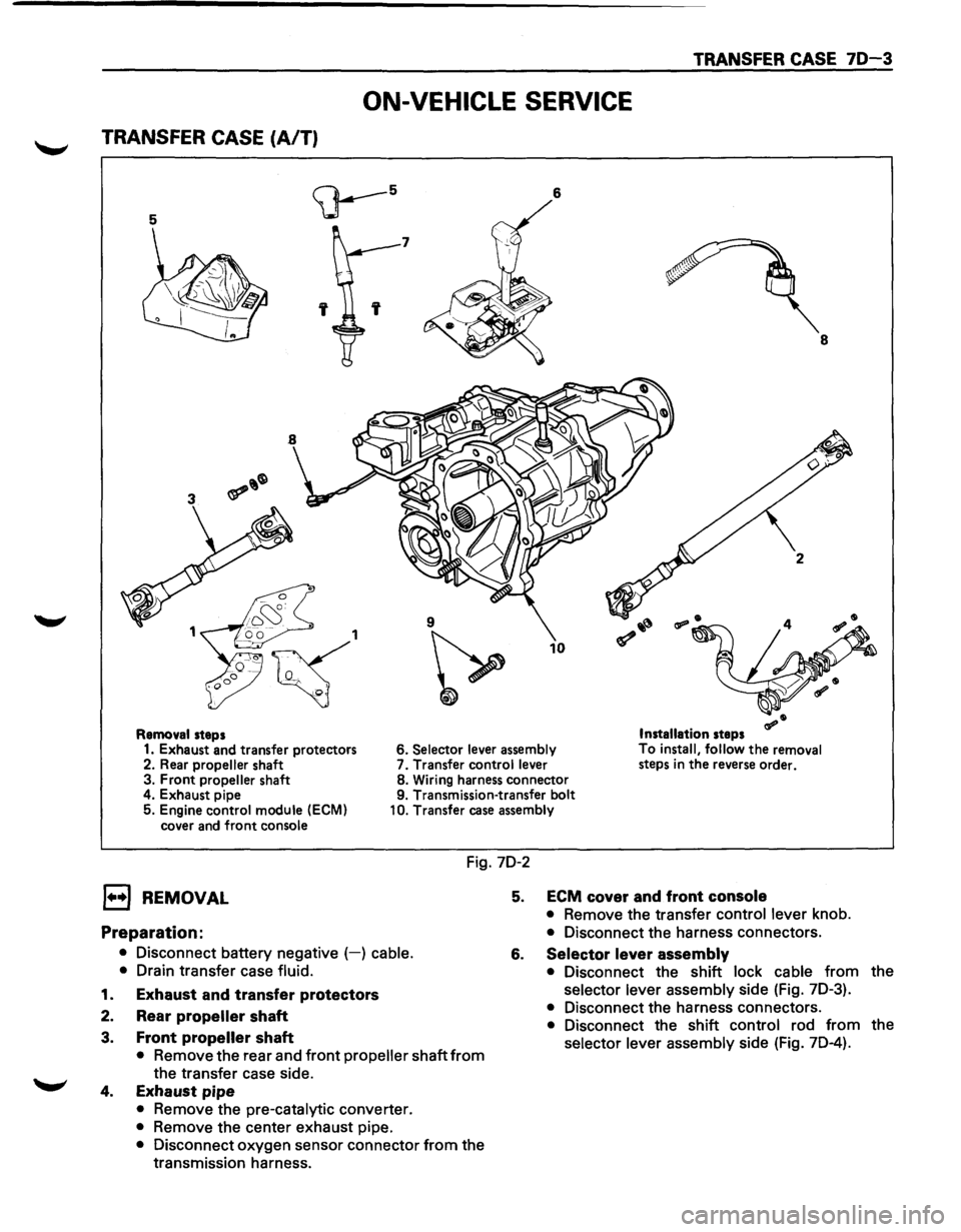
TRANSFER CASE (A/T)
5
<;J---5 6
7
' 8
9
~
10
Removal steps Installation steps
1. Exhaust and transfer protectors 6. Selector lever
assembly To
install, follow the removal
steps in the reverse order.
2. Rear propeller shaft 7.
Transfer control lever
3. Front propeller shaft 8.
Wiring harness connector
4. Exhaust pipe 9. Transmission-transfer bolt
5. Engine control module
(ECM)
cover and front console 10.
Transfer case assembly
Fig. 7D-2
l••l REMOVAL
Preparation:
• Disconnect battery negative (-) cable.
•
Drain transfer case fluid.
1. Exhaust and transfer protectors
2. Rear propeller shaft
3. Front propeller shaft
• Remove the rear and front propeller shaft from
the transfer case side.
4. Exhaust pipe
• Remove the pre-catalytic converter.
• Remove the center exhaust pipe.
• Disconnect oxygen sensor connector from the
transmission harness.
5. ECM cover and front console
• Remove the transfer control lever knob.
• Disconnect the harness connectors.
6. Selector lever assembly
• Disconnect the shift lock cable from the
selector lever assembly side (Fig. 7D-3).
• Disconnect the harness connectors.
• Disconnect the shift control rod from the
selector lever assembly side (Fig. 7D-4).
Page 1219 of 1928
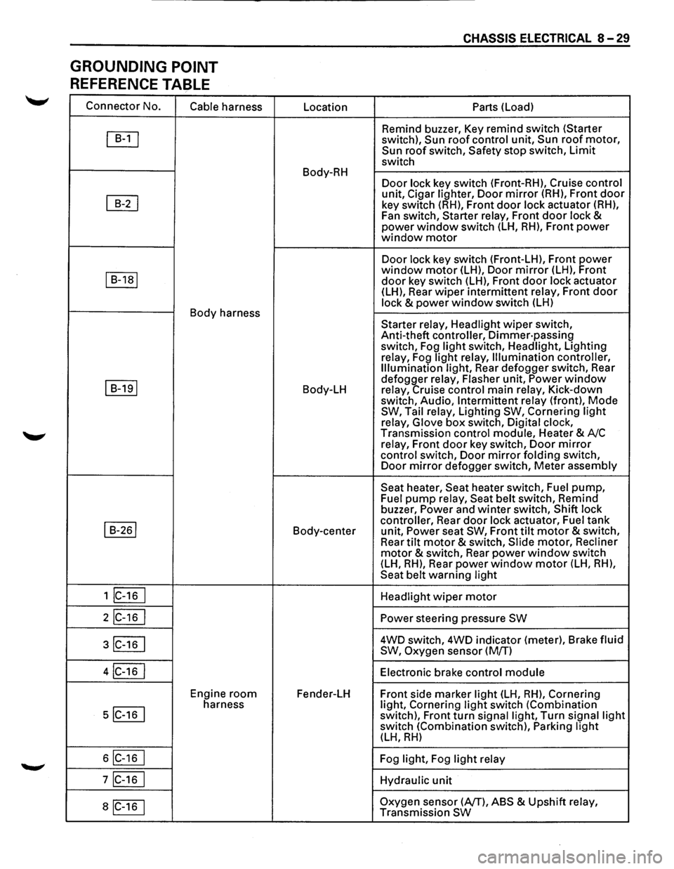
GROUNDING POINT
REFERENCE TABLE
Connector No.
Cable harness
~
~
I B-1a1
Body harness
I B-191
I B-261
1 lc-16 I
2IC-16 I
3IC-16 I
4IC-16 I
Engine room
5IC-16 I
harness
6IC-16 I
7IC-16 I
aiC-16 1
Location
Body-RH
Body-LH
Body-center
Fender-LH
CHASSIS ElECTRICAL 8-29
Parts (Load)
Remind buzzer, Key remind switch (Starter
switch),
Sun roof control unit, Sun roof motor, Sun roof switch, Safety stop switch, Limit
switch
Door lock key switch (Front-RH), Cruise control
unit, Cigar lighter, Door mirror (RH), Front door
key switch (RH), Front door lock actuator (RH),
Fan switch, Starter relay, Front
door lock & power window switch (LH, RH), Front power window motor
Door lock key switch (Front-LH), Front power window motor (LH), Door mirror (LH), Front
door key switch (LH), Front door lock actuator
(LH), Rear wiper intermittent relay, Front door
lock & power window switch (LH)
Starter relay, Headlight
wiper switch,
Anti-theft controller,
Dimmer·passing switch, Fog light switch, Headlight, Lighting
relay, Fog
light relay, Illumination controller,
Illumination light, Rear defogger switch, Rear
defogger relay, Flasher unit,
Power window relay, Cruise control main relay, Kick-down
switch, Audio, Intermittent relay (front), Mode SW, Tail relay, Lighting SW, Cornering light
relay, Glove box switch, Digital clock,
Transmission control module, Heater & A/C
relay, Front
door key switch, Door mirror
control switch, Door mirror folding switch,
Door mirror defogger switch, Meter assembly
Seat heater, Seat heater switch, Fuel pump, Fuel pump relay, Seat belt switch, Remind
buzzer, Power and winter switch, Shift lock
controller, Rear
door lock actuator, Fuel tank
unit, Power seat SW, Front tilt motor & switch,
Rear tilt motor & switch, Slide motor, Recliner
motor & switch, Rear power window switch
(LH, RH), Rear power window motor (LH, RH),
Seat belt warning light
Headlight
wiper motor
Power steering pressure SW
4WD switch, 4WD indicator (meter), Brake fluid
SW, Oxygen sensor (M/T)
Electronic brake control
module
Front side marker light (LH, RH), Cornering
light, Cornering light switch (Combination
switch), Front turn signal light, Turn signal light switch (Combination switch), Parking light (LH, RH)
Fog light, Fog light relay
Hydraulic
unit
Oxygen sensor (AfT), ABS & Upshift relay,
Transmission SW
Page 1478 of 1928
8-288 CHASSIS ELECTRICAL
METER AND WARNING/INDICATOR LIGHT
GENERAL DESCRIPTION
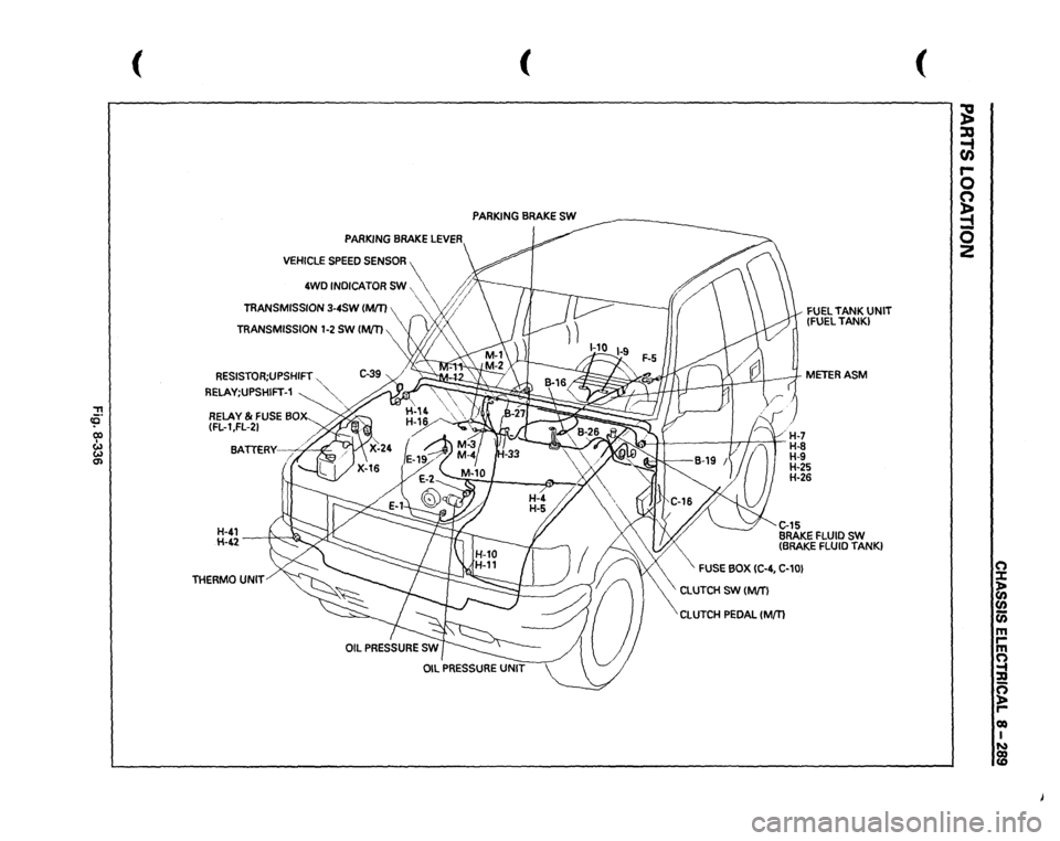
The circuit consists of the starter switch, meter assembly, vehicle speed sensor, clutch switch, transmission
switch, lighting switch,
turn signal switch, thermo unit, oil pressure unit, Engine Control Module, fuel tank unit,
4WD
SW, oil pressure switch, parking brake switch, brake fluid switch, seat belt switch and illumination
controller.
The meter ASM contains the speedometer, tachometer, voltmeter, engine coolant temperature gauge, oil
pressure gauge, fuel gauge and warning/indicator lights.
The meter warning/indicator lights and
their bulb sockets are a unit, they are installed from the back of the
speedometer assembly.
Page 1479 of 1928
::!!
(
(
PARKING
BRAKE
SW
PARKING
BRAKE
LEVER
VEHICLE
SPEED
SENSOR
4WD
INDICATOR
SW,
~
' '
/;~>
TRANSMISSION
3-4SW
IMJT)
"vf;/
RESISTOR;UPSHIFT
."
RELAY;UPSHIFT-1
~":'""
RELAY
& FUSE
BOX-_
(FL-1
,FL-21 BA.
TTERY--.;:;4"~
H-41 H-42
-----;1-"'.,.,-~
THERMO
UNIT
FUEL
TANK
UNIT
(FUEL
TANK)
METERASM
~
16)
1 /
1
(
H-7
/'1'-J
? I n
H-8 H-9 H-25
H-26 C..15 BRAKE
FLUID
SW
(BRAKE
FLUID
TANK}
FUSE
BOX
IC-4,
C-10}
\CLUTCH
SW
(M/T)
CLUTCH
PEDAL
(Mm
(
~ ::xs ~ r-0 0 ~ -0 2
(") :X: ~ en (i) m rm (") ~ g roo I ~