steering wheel ISUZU TROOPER 1995 Repair Manual
[x] Cancel search | Manufacturer: ISUZU, Model Year: 1995, Model line: TROOPER, Model: ISUZU TROOPER 1995Pages: 1928
Page 698 of 1928
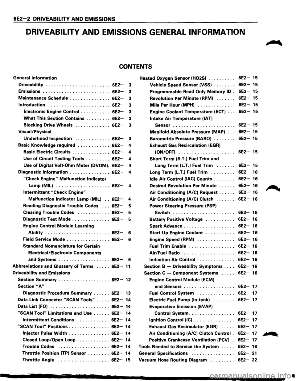
6E2-2 DRIVEABILITY AND EMISSIONS
DRIVEABILITV AND EMISSIONS GENERAL INFORMATION
CONTENTS
General Information
Driveability ....................... .
Emissions
........................ .
Maintenance
Schedule .............. .
Introduction ...................... .
Electronic Engine
Control .......... .
What This Section Contains ........ .
Blocking Drive Wheels
Visual/Physical
Underhood Inspection
6E2-3
6E2-3
6E2-3
6E2-3
6E2-3
6E2-3
6E2-3
6E2-3
Basic
Knowledge required . . . . . . . . . . . . 6E2-4
Basic Electric Circuits . . . . . . . . . . . . . .
6E2-4
Use
of Circuit Testing Tools . . . . . . . . . 6E2-4
Use
of Digital Volt-Ohm Meter (DVOM). 6E2-4
Diagnostic
Information . . . . . . . . . . . . . . . 6E2-4
"Check Engine" Malfunction Indicator
Lamp (MIL) . . . . . . . . . . . . . . . . . . . . 6E2-4
Intermittent "Check Engine"
Malfunction Indicator Lamp (MIL) . . 6E2-4
Reading Diagnostic
Trouble Codes . . . 6E2-5
Clearing
Trouble Codes . . . . . . . . . . . . 6E2-5
Diagnostic Test
Mode .............. 6E2-5
Engine Control
Module Learning
Ability . . . . . . . . . . . . . . . . . . . . . . . . 6E2-6
Field
Service Mode . . . . . . . . . . . . . . . . 6E2-6
Standard Nomenclature
for Certain
Electrical/Electronic
Components
and Systems . . . . . . . . . . . . . . . . . . . 6E2-6
Abbreviations and Glossary of Terms ..... 6E2-11
Driveability and Emissions
Section Summary ................... 6E2-12
Section .,. A"
Diagnostic Procedure Summary ...... 6E2-13
Data Link Connector
"SCAN Tools" ..... 6E2-14
Data
List (FO) ...................... 6E2-14
"SCAN Tool" Limitations and Use ...... 6E2-14
Intermittent Conditions ............ 6E2-14
"SCAN Tool" Positions ............... 6E2-14
Injector Pulse Width ............... 6E2-14
Closed Loop/Open Loop . . . . . . . . . . . .
6E2-14
Trouble Codes ................... 6E2-14
Throttle Position (TP) Sensor . . . . . . . . 6E2-14
Throttle Angle . . . . . . . . . . . . . . . . . . . 6E2-15 Heated
Oxygen
Sensor (H02S)
Vehicle Speed Sensor (VSS) ....... .
Programmable Read Only Memory ID .
Revolution
Per Minute (RPM) ...... .
Mile Per Hour (MPH) ............. .
Engine
Coolant Temperature (ECT) .. .
Intake Air Temperature (IAT)
Sensor
...................... .
Manifold Absolute Pressure (MAP) .. .
Barometric Pressure (BARO) ....... .
Exhaust Gas Recirculation
(EGR)
(ON/OFF) .................... .
Short Term (S.T.) Fuel Trim and
Long Term
(LT.) Fuel Trim ...... .
Long Term
(LT.) Fuel Trim ........ .
Idle Air Control (lAC) Counts ....... .
Desired Revolution
Per Minute ..... .
Air Conditioning (A/C) Request ..... .
Air Conditioning (A/C) Clutch ...... .
Power Steering Pressure (PSP)
Switch ...................... .
Battery Positive Voltage .......... .
Spark Advance .................. .
Start Up Engine Coolant .......... .
Engine
Speed (RPM) ............. .
Fuel Trim Enable ................ .
Air/Fuel Ratio .................. .
Induction Air Control ............. .
Section B -Driveability Symptoms ... .
Section C -Component Systems .... .
Engine
Control Module (ECM)
and
Sensors .................. .
Fuel Control System ............. .
Electric
Fuel Pump (in-tank) ....... .
Evaporative Emission
(EVAP)
Control System ................ .
Ignition Control (IC) .............. .
Exhaust Gas Recirculator
(EGR) .... .
Air Conditioning (A/C) Clutch Control .
Positive Crankcase Ventilation (PCV) .
Tools Needed
to Service the System .... .
General Specifications
............... .
Vacuum Hose Routing Diagram
........ .
6E2-15
6E2-15
6E2-15
6E2-15
6E2-15
6E2-15
6E2-15
6E2-15
6E2-15
6E2-15
6E2-15
6E2-16
6E2-16
6E2-16
6E2-16
6E2-16
6E2-16
6E2-16
6E2-16
6E2-16
6E2-16
6E2-16
6E2-16
6E2-16
6E2-16
6E2-16
6E2-17
6E2-17
6E2-17
6E2-17
6E2-17
6E2-17
6E2-17
6E2-17
6E2-18
6E2-21
6E2-22
~
... ...
•
Page 729 of 1928
DRIVEABILITY AND EMISSIONS 6E2-33
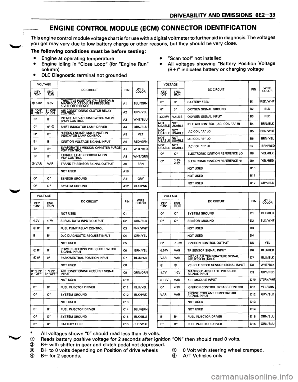
ENGINE CONTROL MODULE (ECM) CONNECTOR IDENTIFICATION
This engine control module voltage chart is for use with a digital voltmeter to further aid in diagnosis. The voltages
you get may vary due to low battery charge or other reasons, but they should be very close.
The following conditions must be before testing:
• Engine at operating temperature • "Scan tool" not installed
•
Engine idling in "Close Loop" (for "Engine Run"
column) •
All voltages showing "Battery Position Voltage
(8+)" indicates battery or charging voltage
•
DLC Diagnostic terminal not grounded
VOLTAGE VOLTAGE
DC CIRCUIT PIN WIRE
KEY ENG. COLOR
"ON" RUN
DC CIRCUIT PIN WIRE
KEY ENG. COLOR "ON" RUN
ID 5.0V 5.0V THROTILE
POSITION ~TP~ SENSOR & MANIFOLD ABSOLUT P ESSURE A1 BLU/ORN 8+ B+ BATIERY FEED B1 RED/WHT
5 VOLT REFERENCE B+"ON" B+ OFF AIR CONDITIONING CLUTCH RELAY A2 GRY/YEL 0 "OFF" 0* ON
CONTROL o• o• OXYGEN SIGNAL GROUND 82 BLU
B+ s+ INTAKE
AIR VACUUM SWITCH VALVE A3 WHT/BLU (VSV) CONTROL
o• O*® SHIFT INDICATOR LAMP DRIVER A4 ORN/BLU .430MV
VALlES OXYGEN
SIGNAL INPUT
B3 RED
NOT NOT
IDLE AIR CONTROL (lAC) COIL "A" HI B4 8RN/BLK USABLE
USABLE
o• B+ "CHECK ENGINE" MALFUNCTION A5 VLT INDICATOR LAMP CONTROL
B+ B+ IGNITION VOLTAGE SIGNAL INPUT
AS RED/GRN
NOT NOT
lAC COIL "A" LO B5 8RN/WHT USABLE USABLE
NOT NOT
lAC COIL
"B" LO B6 BRN/YEL USABLE
USABLE
B+ B+ EVAPORATE EMISSION CANISTER PURGE A7 WHT/RED VSVCONTROL NOT
NOT
lAC COIL "B" HI B7 BRN/RED USABLE
USABLE
B+ 8~ EXHAUST GAS RECIRCULATION AS WHT/GRN VSV CONTROL
@VAR VAR TRANS TP SENSOR SIGNAL OUTPUT A9 8RN
o• o• ELECTRONIC IGNITION REFERENCE LO 88 YEL/BLK
o• 1.1V-ELECTRONIC
IGNITION REFERENCE HI B9 YEL/RED
2.4V
NOT USED B10
NOT USED
A10
NOT USED
B11 o• o• SENSOR GROUND A11 GRY
NOT USED B12 GRY/BLU o• o• SYSTEM
GROUND A12 8LK/PNK
VOLTAGE
VOLTAGE
DC CIRCUIT PIN WIRE
KEY ENG. COLOR DC CIRCUIT PIN WIRE
KEY ENG. COLOR "ON" RUN "ON" RUN
NOT USED C1 o• o• SYSTEM GROUND D1 BLK/BLU
4.7V 4.7V
SERIAL DATA INPUT/OUTPUT C2 ORN/8LK o• 0* SENSOR GROUND D2 BLK/WHT
@) B+ B+ FUEL PUMP RELAY CONTROL C3 PNK/WHT NOT USED D3
B+ B+ DLC DIAGNOSTIC REQUEST INPUT C4 ORN/YEL NOT USED D4
NOT USED C5 o• .1·.2V IGNITION
CONTROL OUTPUT D5 YEL
@B+ B+ POWER STEERING PRESSURE SWITCH C6 GRN/YEL SIGNAL INPUT 0.54V VAR
TP SENSOR
SIGNAL INPUT D6 BLU/RED
@O* o• PARK/NEUTRAL POSITION
INPUT C7 BLU/PNK VAR
VAR INTAKE AIR TEMPERATURE SIGNAL D7 BLU/BLK INPUT D7 BLU/BLK
NOT USED CB ® ® VEHICLE SPEED SENSOR
SIGNAL INPUT D8 WHT/BLK
B+"ON" 0 "ON" AIR CONDITIONING REQUEST SIGNAL C9 GRN/ORN
0 "OFF" B+"OFF"
INPUT 4.7V 1-2V MANIFOLD ABSOLUTE PRESSURE D9 GRY/RED SIGNAL
INPUT
NOT USED
C10 8-10V
VAR K.S.
MODULE INPUT D10 LTGRN/WHT
B+ B+ FUEL INJECTOR
DRIVER C11 BLU/YEL o• 4.9V IGNITION CONTROL BYPASS CONTROL D11 YELIGRN
o• o• SYSTEM GROUND
C12 BLK/PNK VAR VAR ENGINE COOLANT TEMPERATURE
D12 GRY/BLK SIGNAL
INPUT
NOT USED
C13 NOT USED D13
B+ 8+
FUEL INJECTOR DRIVER C14 BLU/GRN NOT USED D14
o• o• SYSTEM GROUND
C15 BLK/BLU B+ B+ FUEL INJECTOR DRIVER D15 ORN/BLU
8+ B+ BATIERY FEED C16 RED/WHT B+ 8+
FUEL INJECTOR DRIVER D16 ORN/8LU
* All voltages shown "0" should read less than .5 volts.
Reads battery positive voltage for 2 seconds after ignition "ON" then should read 0 volts. CD
®
® @
B+ with shifter in gear and clutch pedal not depressed.
B+ to 0 volts depending on Position of drive wheels
B+ for 2 seconds.
@
®
0 Volt with steering wheel cramped.
A/T Vehicles only
Page 800 of 1928
6E2-1 04 DRIVEABILITV AND EMISSIONS
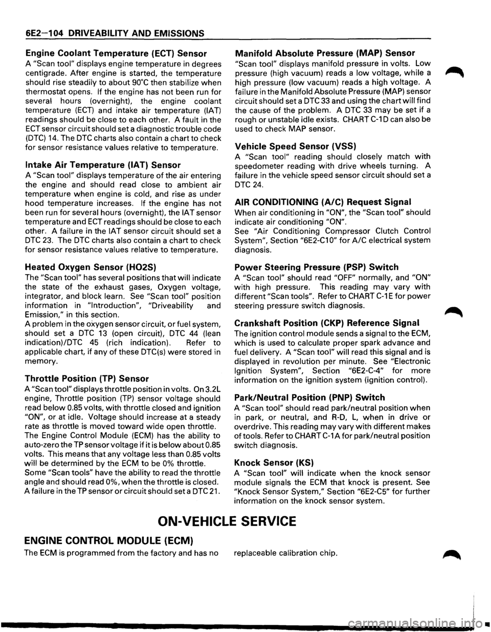
Engine Coolant Temperature (ECT) Sensor
A "Scan tool" displays engine temperature in degrees
centigrade. After engine is started, the temperature
should rise steadily to about 90°C then stabilize when
thermostat opens. If the engine has not been run for
several hours (overnight), the engine coolant
temperature (ECT) and intake air temperature (IAT)
readings should be close to each other. A fault in the
ECT sensor circuit should set a diagnostic trouble code
(DTC) 14. The DTC charts also contain a chart to check
for sensor resistance values relative to temperature.
Intake Air Temperature (IAT) Sensor
A "Scan tool" displays temperature of the air entering
the engine and
should read close to ambient air
temperature when engine
is cold, and rise as under
hood temperature increases.
If the engine has not
been run for several hours (overnight), the IAT sensor
temperature and
ECT readings should be close to each
other. A
failure in the IAT sensor circuit should set a
DTC 23. The DTC charts also contain a chart to check
for sensor resistance values relative to temperature.
Heated Oxygen Sensor (H02S)
The "Scan tool" has several positions that will indicate
the state
of the exhaust gases, Oxygen voltage,
integrator, and block learn. See "Scan tool" position
information in
"Introduction", "Driveability and
Emission," in this section.
A
problem in the oxygen sensor circuit, or fuel system,
should set a DTC 13 (open circuit), DTC 44 (lean
indication)/DTC 45 (rich indication). Refer to
applicable chart, if any of these DTC(s) were stored in
memory.
Throttle Position (TP) Sensor
A "Scan tool" displays throttle position in volts. On 3.2L
engine, Throttle position
(TP) sensor voltage should
read below 0.85 volts, with throttle closed and ignition
"ON", or at idle. Voltage should increase at a steady
rate
as throttle is moved toward wide open throttle.
The Engine
Control Module (ECM) has the ability to
auto-zero the TP sensor voltage if it is below about 0.85
volts. This means that any voltage less than 0.85 volts
will
be determined by the ECM to be 0% throttle.
Some
"Scan tools" have the ability to read the throttle
angle and should read 0%, when the throttle is closed.
A failure in the TP sensor or circuit should set a DTC 21.
Manifold Absolute Pressure (MAP) Sensor
"Scan tool" displays manifold pressure in volts. Low
pressure (high vacuum) reads a
low voltage, while a
high pressure
(low vacuum) reads a high voltage. A
failure in the Manifold Absolute Pressure (MAP) sensor
circuit
should set a DTC 33 and using the chart will find
the cause
of the problem. A DTC 33 may be set if a
rough or unstable
idle exists. CHART C-1 D can also be
used
to check MAP sensor.
Vehicle Speed Sensor (VSS)
A "Scan tool" reading should closely match with
speedometer reading with drive wheels turning. A
failure in the vehicle speed sensor circuit should set a
DTC 24.
AIR CONDITIONING (A/C) Request Signal
When air conditioning in "ON", the "Scan tool" should
indicate air conditioning "ON".
See
"Air Conditioning Compressor Clutch Control
System",
Section "6E2-C1 0" for A/C electrical system
diagnosis.
Power Steering Pressure (PSP) Switch
A "Scan tool" should read "OFF" normally, and "ON"
with high pressure. This reading may vary with
different "Scan tools". Refer to CHART C-1 E for power
steering pressure switch diagnosis.
Crankshaft Position (CKP) Reference Signal
The ignition control module sends a signal to the ECM,
which is used to calculate proper spark advance and
fuel delivery. A "Scan tool" will read this signal and is
displayed in revolution per minute.
See "Electronic
Ignition System",
Section "6E2-C-4" for more
information on the ignition system (ignition control).
Park/Neutral Position (PNP) Switch
A "Scan tool" should read park/neutral position when
in park, or neutral, and R-D, L, when in drive or
overdrive. This reading may vary with different makes
of tools. Refer to CHART C-1 A for park/neutral position
switch diagnosis.
Knock Sensor (KS)
A "Scan tool" will indicate when the knock sensor
module signals the ECM that knock is present. See
"Knock
Sensor System," Section "6E2-C5" for further
information on the knock sensor system.
ON-VEHICLE SERVICE
ENGINE CONTROL MODULE (ECM)
The ECM is programmed from the factory and has no replaceable calibration chip.
•
Page 803 of 1928
New or service sensors will already have the
compound
applied to the threads. If a sensor is
removed
from an engine and iffor any reason it
is to be reinstalled, the threads must have anti
seize compound
applied before reinstallation.
•
Apply anti-seize compound or equivalent to
threads of oxygen sensor if necessary.
• Tighten the oxygen sensor to the specified
torque.
1~1 Torque N·m (lb·ft) 55 (40)
1. H02S wiring connector
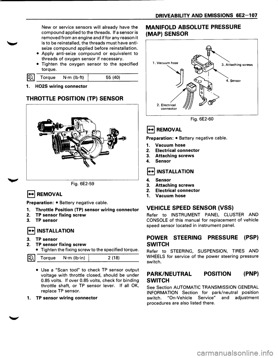
THROTTLE POSITION (TP) SENSOR
Fig. 6E2-59
E) REMOVAL
Preparation: • Battery negative cable.
1. Throttle Position (TP) sensor wiring connector
2. TP sensor fixing screw
3. TP sensor
I••IINSTALLATION
3. TP sensor
2. TP sensor fixing screw
• Tighten the fixing screw to the specified torque.
~~~ Torque N·m (lb·in) I 2 (18)
• Use a "Scan tool" to check TP sensor output
voltage with throttle closed, should be under
0.85 volts. If over 0.85 volts, check for binding
throttle shaft, or TP sensor lever. If all OK,
replace TP sensor.
1.
TP sensor wiring connector
DRIVEABILITY AND EMISSIONS 6E2-1 07
MANIFOLD ABSOLUTE PRESSURE
(MAP) SENSOR
1. Vacuum hose
) 0~
2 .• ,.~,,~,~
conne~ JJJ
4. Sensor
Fig. 6E2-60
E) REMOVAL
Preparation: • Battery negative cable.
1. Vacuum hose
2. Electrical connector
3. Attaching screws
4. Sensor
I••IINSTALLATION
4. Sensor
3. Attaching screws
2. Electrical connector
1. Vacuum hose
VEHICLE SPEED SENSOR (VSS)
Refer to INSTRUMENT PANEL CLUSTER AND
CONSOLE of this manual for replacement of vehicle
speed sensor located in instrument panel.
POWER STEERING PRESSURE (PSP)
SWITCH
Refer to STEERING, SUSPENSION, TIRES AND
WHEELS for service of the power steering pressure
switch.
PARK/NEUTRAL
SWITCH POSITION
(PNP}
See
Section AUTOMATIC TRANSMISSION GENERAL
INFORMATION Section for park/neutral position
switch.
"On-Vehicle Service" and adjustment
procedures are
also listed there.
Page 808 of 1928
6E2-112 DRIVEABILITY AND EMISSIONS
CHART C-1E
POWER STEERING PRESSURE (PSP) SWITCH DIAGNOSIS
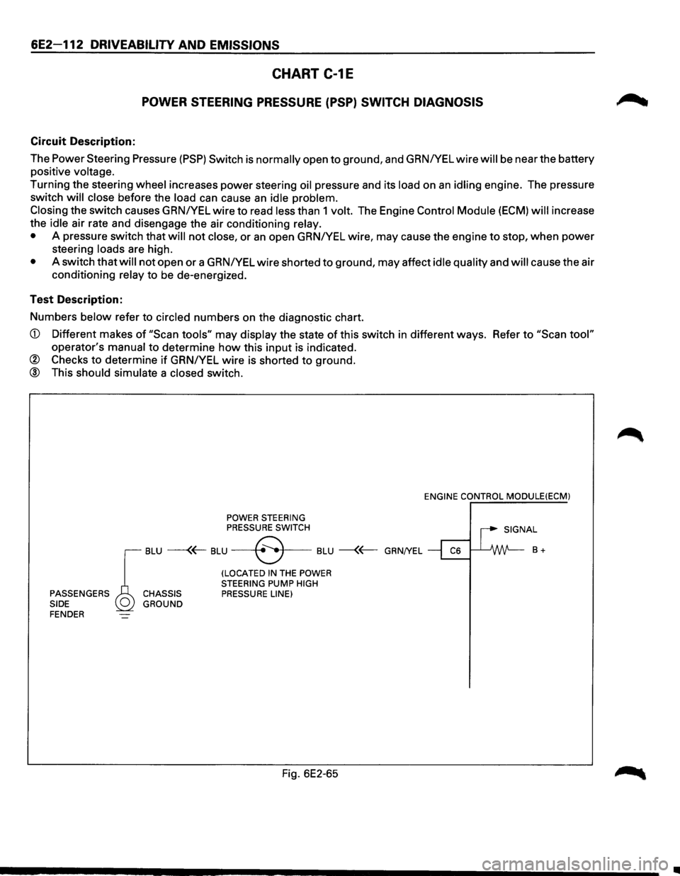
Circuit Description:
The Power Steering Pressure
(PSP) Switch is normally open to ground, and GRNIYEL wire will be near the battery
positive
voltage.
Turning the steering wheel increases power steering oil pressure and its load on an idling engine. The pressure
switch
will close before the load can cause an idle problem.
Closing
the switch causes GRN/YEL wire to read less than 1 volt. The Engine Control Module (ECM) will increase
the
idle air rate and disengage the air conditioning relay.
•
A pressure switch that will not close, or an open GRNIYEL wire, may cause the engine to stop, when power
steering loads are high.
• A switch that will not open or a GRNIYEL wire shorted to ground, may affect idle quality and will cause the air
conditioning
relay to be de-energized.
Test Description:
Numbers
below refer to circled numbers on the diagnostic chart.
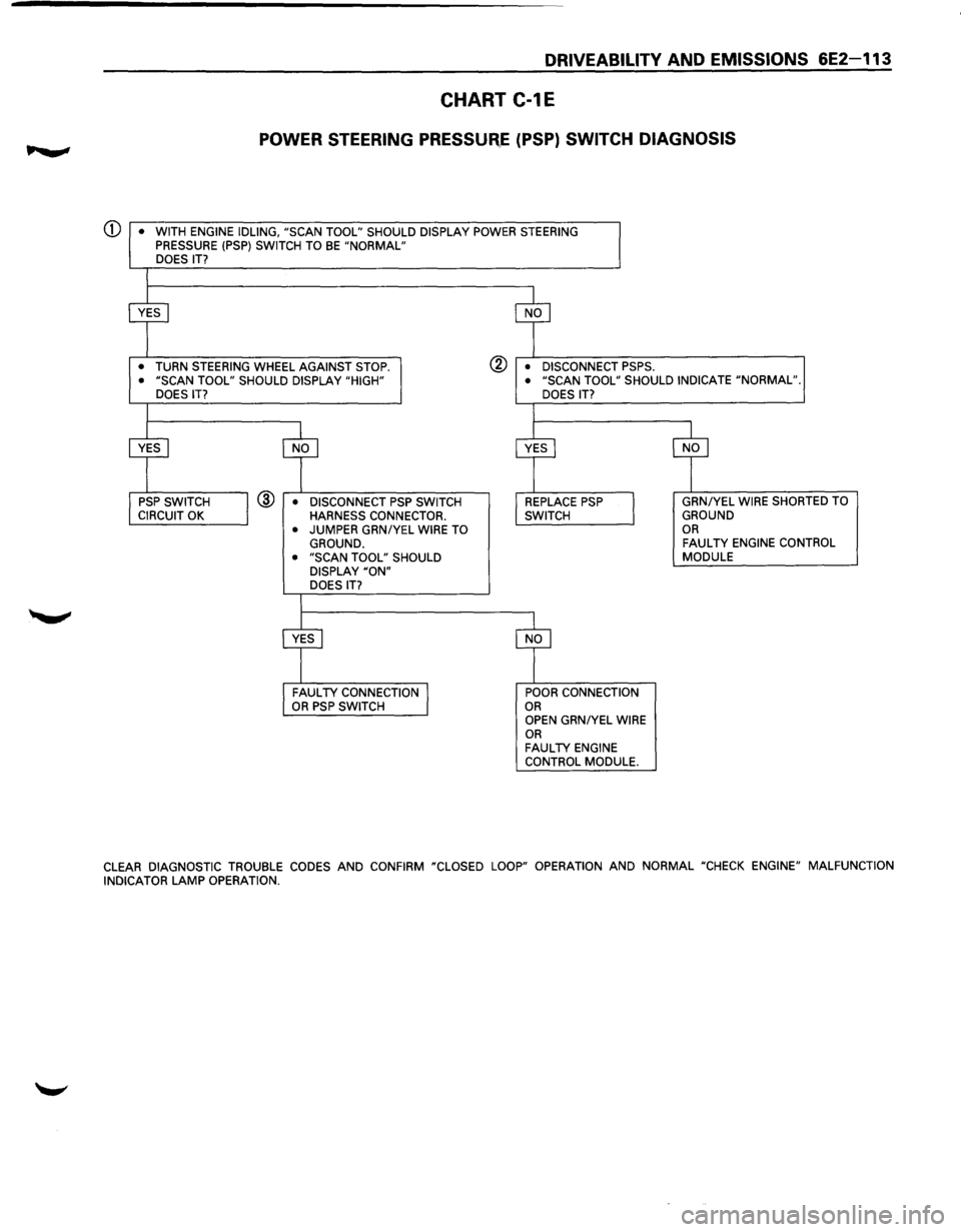
CD Different makes of "Scan tools" may display the state of this switch in different ways. Refer to "Scan tool"
operator's manual to determine how this input is indicated.
® Checks to determine if GRNIYEL wire is shorted to ground.
@ This should simulate a closed switch.
POWER STEERING PRESSURE SWITCH ENGINE
CONTROL
MODULE(ECM)
I SIGNAL
r
BLU ---(~ BLU --+8 .. •f---BLU --{~ GRN/YEL ~ ~ B +
(LOCATED IN THE POWER
STEERING PUMP HIGH PASSENGERS CHASSIS PRESSURE LINE)
SIDE GROUND
FENDER
Fig. 6E2-65
•
Page 809 of 1928
DRIVEABILITY AND EMISSIONS 6E2-113
CHART C-1E
POWER STEERING PRESSUR,.E (PSP) SWITCH DIAGNOSIS
CD • WITH ENGINE IDLING, "SCAN TOOL" SHOULD DISPLAY POWER STEERING PRESSURE (PSP) SWITCH TO BE "NORMAL" DOES IT?
•
TURN STEERING WHEEL AGAINST STOP. ® • DISCONNECT PSPS. • "SCAN TOOL" SHOULD DISPLAY "HIGH"
DOES IT? • "SCAN TOOL" SHOULD INDICATE "NORMAL".
@ • DISCONNECT PSP SWITCH HARNESS CONNECTOR.
• JUMPER GRNIYEL WIRE TO GROUND. • "SCAN TOOL" SHOULD DISPLAY "ON" DOES IT? DOES
IT?
POOR CONNECTION OR OPEN GRN/YEL WIRE OR FAULTY ENGINE
CONTROL MODULE. GRN/YEL
WIRE SHORTED TO GROUND OR FAULTY ENGINE
CONTROL MODULE
CLEAR
DIAGNOSTIC TROUBLE CODES AND CONFIRM "CLOSED LOOP" OPERATION AND NORMAL "CHECK ENGINE" MALFUNCTION
INDICATOR LAMP OPERATION.
Page 823 of 1928
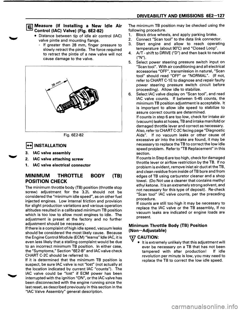
1~1 Measure (If Installing a New Idle Air
Control (lAC) Valve) (Fig. 6E2-82)
• Distance between tip of idle air control (lAC)
valve pintle and mounting flange.
-
If greater than 28 mm, finger pressure to
slowly retract the pintle. The force required
to retract the pintle
of a new valve will not
cause damage to the valve.
Fig. 6E2-82
E) INSTALLATION
3. lAC valve assembly
2. lAC valve attaching screw
1. lAC valve electrical connector
MINIMUM THROTTLE BODY (TB)
POSITION CHECK
The minimum throttle body (TB) position (throttle stop
screw) adjustment
for the 3.2L should not be
considered the
"minimum idle speed", as on other fuel
injected engines. Low internal friction and provision
for slight production variations and various operation
altitudes resulted in a calibrated
minimum TB position
which is too
low to allow most engines to idle. The
adjustment is preset at the factory and no further
adjustment should be necessary.
If there is a complaint of high idle speed, vacuum leaks
should be considered the
most likely cause. Because
the Engine
Control Module (ECM) "learns" Idle lAC, it is
even less likely
that a stalling complaint would be due
to
an incorrect minimum TB position. In either case,
the
"Symptoms," Section "6E2-B" and lAC valve check
CHART C-2C should be referred to.
If it is determined that the minimum TB position is
suspect,
be sure lAC valve is not "lost'' (not actually at
the location indicated by current
lAC "counts"). The
lAC valve could be "lost" if ECM power has been
interrupted
with the ignition "ON", or the lAC valve has
been disconnected
with the engine running since the
last reset,
as described previously in this section in the
"lAC Valve Assembly" general description.
DRIVEABILITY AND EMISSIONS 6E2-127
The minimum TB position may be checked using the
following procedure.
1. Block drive wheels, and apply parking brake.
2. Connect "Scan tool" to the data link connector.
3. Start engine and allow to reach operating
temperature (about
go•q and "Closed Loop".
4. A/T-shift to DRIVE ("D") and then back to neutral
("N").
5. Select power steering pressure switch input on
"Scan tool". With air conditioning and all electrical
accessories
"OFF", transmission in natural, "Scan
tool" should read "OFF" or "NORMAL". (If not,
refer to
CHART C-1 E to diagnose and repair faulty
power steering pressure switch circuit before
proceeding).
Allow idle to stabilize.
6. Select lAC valve display on "Scan tool", and read
lAC valve counts. If between 5-45 counts, the
minimum
TB position adjustment is acceptable. It
is important to allow idle speed to stabilize to
assure correct counts are determined.
If counts in step 6 are too low, check for intake air
(vacuum) leaks at hoses,
TB and intake manifold or
damaged throttle lever and correct as necessary.
Also, refer to
CHART C-2C facing page "Diagnostic
Aids". If no vacuum leaks or other cause of
excessive air into the intake are found, it may be
necessary
to replace the TB to correct the low idle
speed problem. Refer to
"TB Replacement" in this
section.
If counts in Step 6 are too high, check for damaged
throttle lever or airflow restriction by the
TB. If no
problem is evident, remove inlet air
duct at the TB,
and
clean residue from inside of TB bore and from
edges of TB using carburetor cleaner and a shop
towel. (Do Not use a cleaner that contains methyl
ethyl ketone.
It is an extremely strong solvent, and
not necessary for this type of deposit). Re-check
"Scan tool" lAC valve counts, per the preceding
procedure.
If counts are still too high it may be necessary to
replace the
lAC valve or the TB assembly, If no
vacuum leaks are indicated
or engine loads are
present.
Minimum Throttle Body (TB) Position
(Non-Adjustable)
\fl CAUTION:
VI • It is extremely unlikely that this adjustment will
ever be necessary on a TB that has not been
tampered
with after production! If idle
revolution per minute is low, you may need
to
replace the TB to correct the low idle speed.
Page 1260 of 1928
I ..
8 -70 CHASSIS ELECTRICAL
When placing a live inflator module on a bench
or other surface, always face the bag and trim
cover up, away from the surface. This is neces
sary so that a free space is provided to allow the
air bag to expand in the unlikely event of acci·
dental
deployment.
4. Steering wheel
• Refer to STEERING WHEEL REPLACEMENT in
Section 3F4.
5. Lighting switch (Combination switch)
• Disconnect the switch connector.
• Remove four screws.
• Remove the lighting switch together with SRS
coil assembly.
'\f CAUTION:
Do not remove SRS coil assembly from the com·
bination switch assembly.
E) INSTALLATION
To install, follow the removal steps in the reverse
order, noting the
following points.
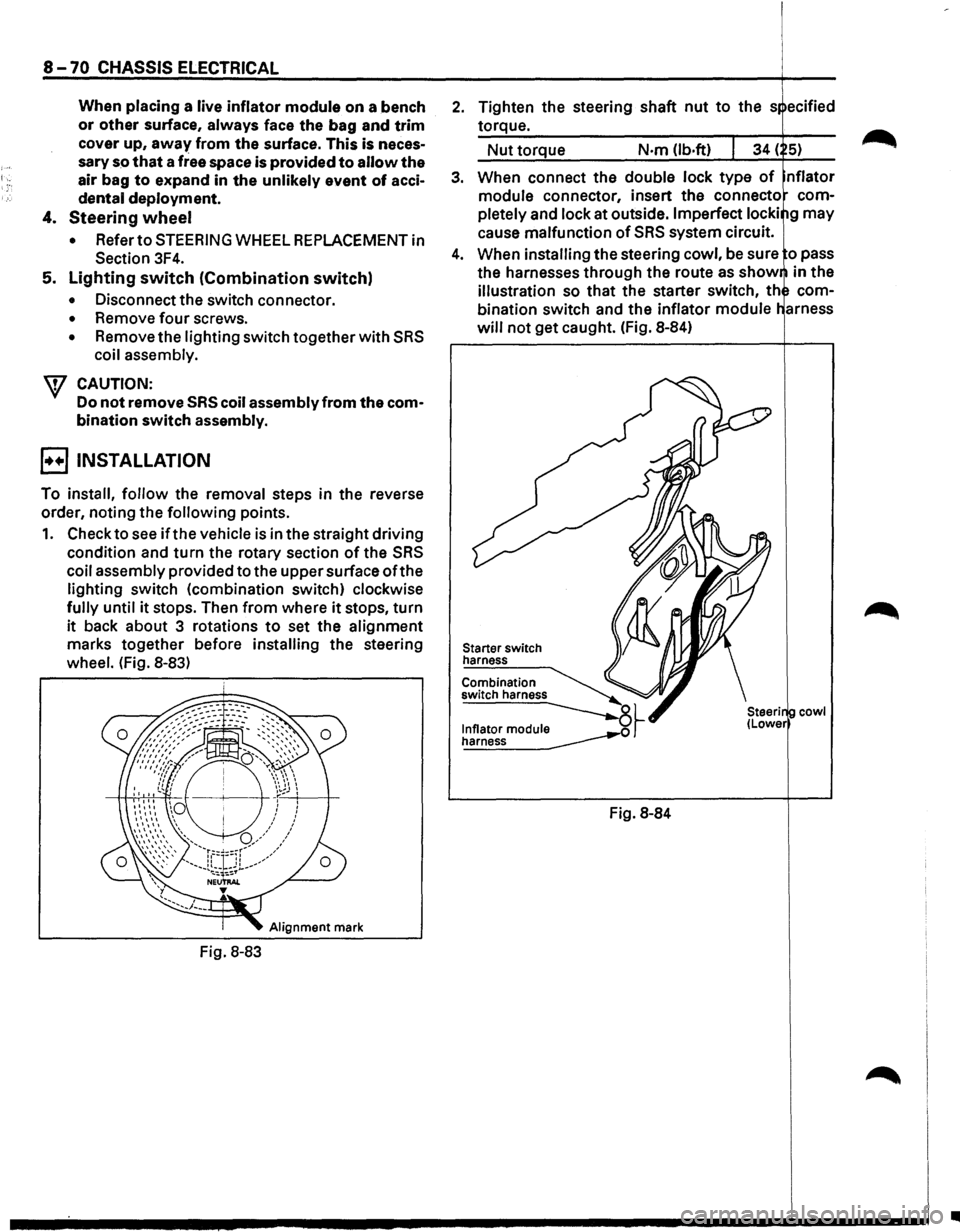
1. Check to see if the vehicle is in the straight driving
condition and turn the rotary section of the SRS
coil assembly provided to the upper surface ofthe
lighting switch (combination switch) clockwise
fully until it stops. Then from where it stops, turn
it back about 3 rotations to set the alignment
marks together before installing the steering
wheel. (Fig. 8-83)
Alignment mark
Fig. 8-83
2. Tighten the steering shaft nut to the s ecified
torque.
Nut torque N·m (lb.ft)
3. When connect the double lock type of nflator
module connector, insert the connecto com
pletely
and lock at outside. Imperfect locki g may
cause malfunction of SRS system circuit.
4. When installing the steering cowl, be sure o pass
the harnesses
through the route as show in the
illustration so that the starter switch, th com
bination switch and the inflator module
will not get caught. (Fig. 8-84)
Starter switch
harness
Combination
switch harness
~~ ~
Fig. 8-84
cowl
•
Page 1572 of 1928
8-382 CHASSIS ELECTRICAL
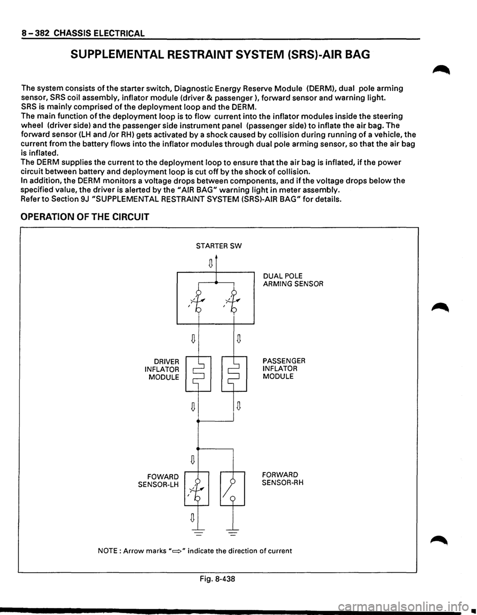
SUPPLEMENTAL RESTRAINT SYSTEM (SRS)-AIR BAG
The system consists of the starter switch, Diagnostic Energy Reserve Module (OERM), dual pole arming
sensor,
SRS coil assembly, inflator module (driver & passenger), forward sensor and warning light.
SRS is mainly comprised of the deployment loop and the DERM.
The main function of the deployment loop is to flow current into the inflator modules inside the steering
wheel (driver side) and the passenger side instrument panel (passenger side) to inflate the air bag. The
forward sensor
(LH and /or RH) gets activated by a shock caused by collision during running of a vehicle, the
current
from the battery flows into the inflator modules through dual pole arming sensor, so that the air bag
is
inflated.
The DERM supplies the current to the deployment loop to ensure that the air bag is inflated, if the power
circuit between battery and deployment loop is cut off by the shock of collision.
In
addition, the DERM monitors a voltage drops between components, and if the voltage drops below the
specified
value, the driver is alerted by the "AIR BAG" warning light in meter assembly.
Refer to Section 9J "SUPPLEMENTAL RESTRAINT SYSTEM (SRS)-AIR BAG" for details.
OPERATION OF THE CIRCUIT
DRIVER
INFLATOR MODULE
FOWARD
SENSOR-LH
D
D
STARTER SW
D
1
DUAL POLE ARMING SENSOR
PASSENGER
INFLATOR
MODULE
FORWARD
SENSOR-RH
NOTE: Arrow marks "c::::>" indicate the direction of current
Fig. 8-438
•
Page 1627 of 1928
Supplemental Restraint System 9J-3
GENERAL DESCRIPTION
RESTRAINT DEVICES
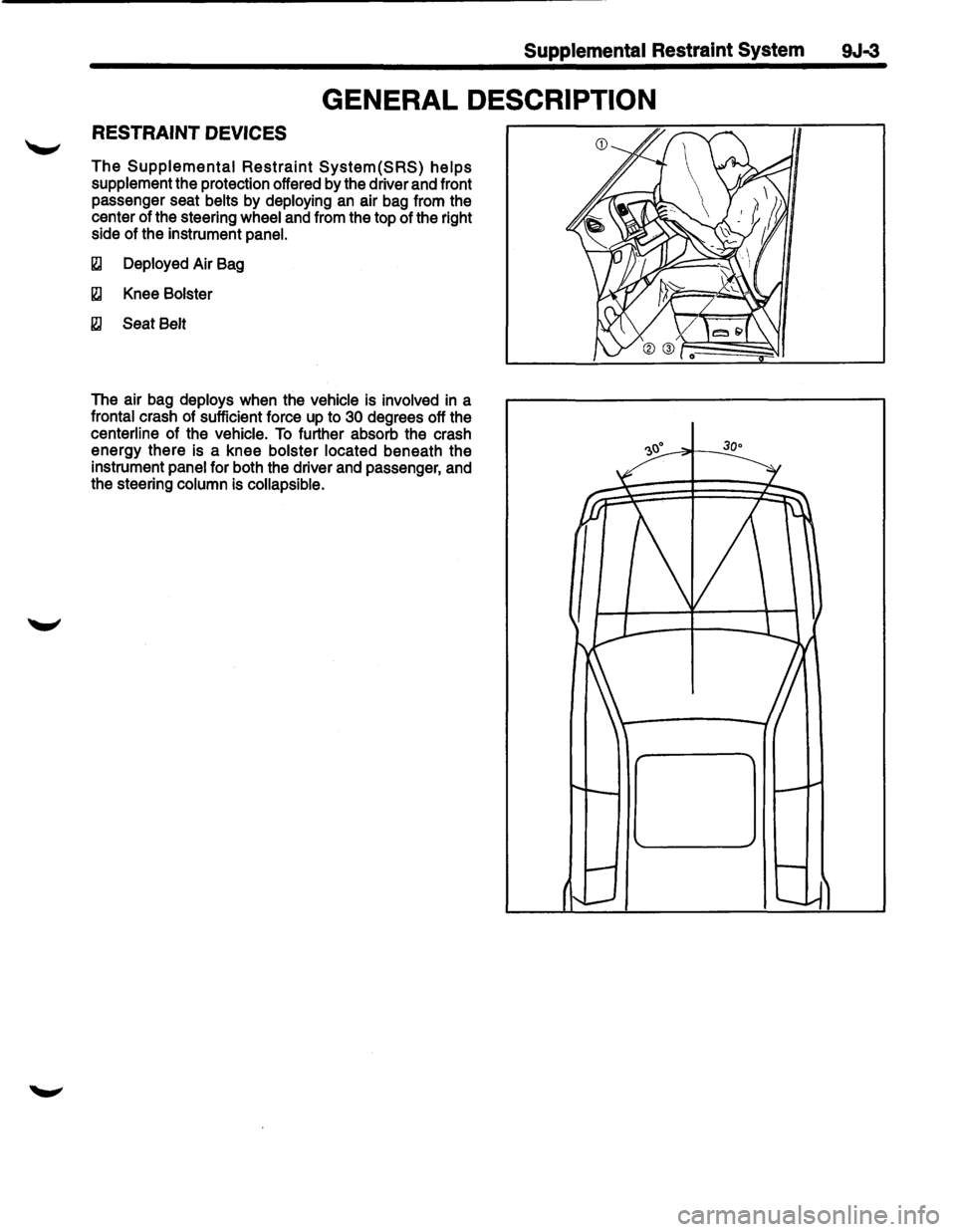
The Supplemental Restraint System(SRS) helps
supplement the protection offered by the driver and front
passenger seat
belts by deploying an air bag from the
center of the steering
wheel and from the top of the right
side of the instrument
panel.
~ Deployed Air Bag
~ Knee Bolster
~ Seat Belt
The air bag deploys when the vehicle is involved in a
frontal crash of sufficient force up to 30 degrees off the
centerline of the vehicle. To further absorb the crash
energy there is a knee
bolster located beneath the
instrument
panel for both the driver and passenger, and
the steering
column is collapsible.