warning ISUZU TROOPER 1995 Repair Manual
[x] Cancel search | Manufacturer: ISUZU, Model Year: 1995, Model line: TROOPER, Model: ISUZU TROOPER 1995Pages: 1928
Page 877 of 1928
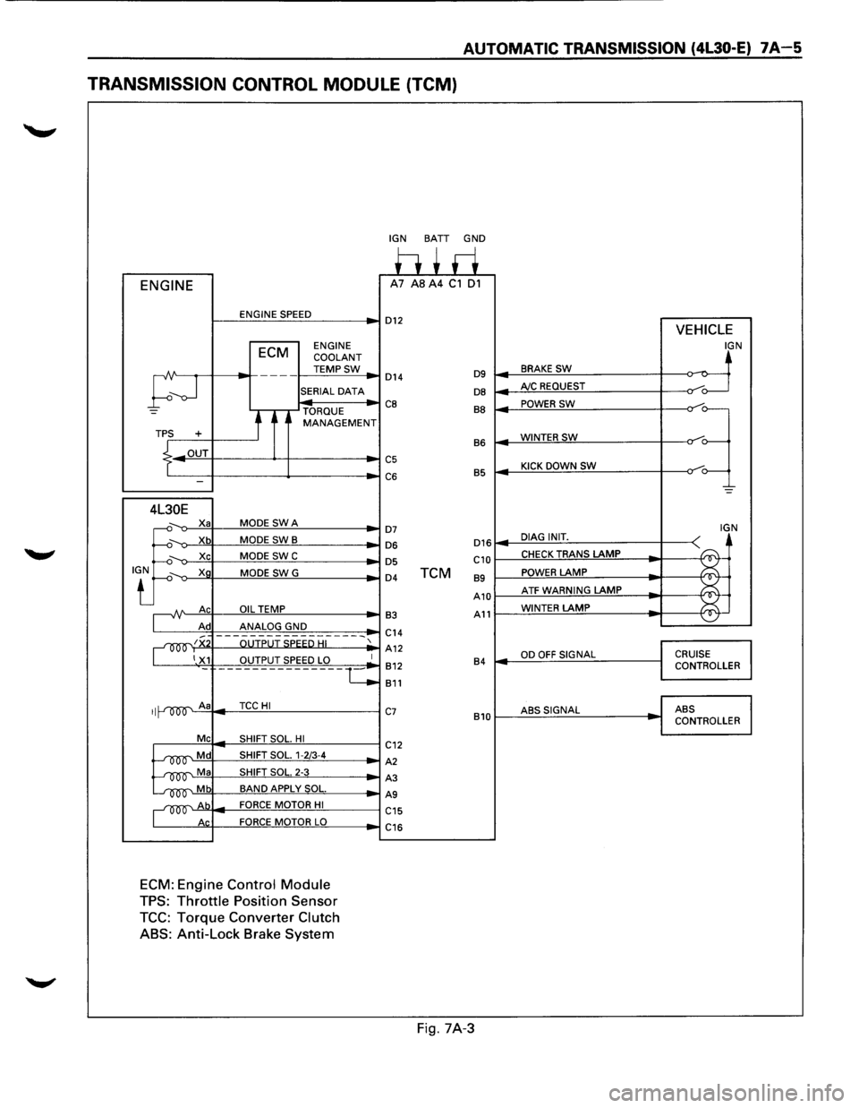
AUTOMATIC TRANSMISSION (4l30-E) 7A-5
TRANSMISSION CONTROL MODULE (TCM)
ENGINE
ENGINE SPEED
ECM ENGINE
COOLANT
TEMPSW
;--J
---
SERIAL DATA
TORQUE
t MANAGEMENT TPS +
.L OUT
I -
4L30E
.J:
X a MODE SWA
Xb MODE SWB
Xc MODE SWC
Xg MODE SWG
A Ac OIL TEMP
Ad ANALOG GND
~~x OUTPUT SPEED HI
1 X1 OUTPUT SPEED LO
II A a TCCHI
Me SHIFT SOL. HI
~Md SHIFT SOL. 1-2/3-4
~Ma SHIFT SOL. 2-3
~Mb BAND APPLY SOL.
~Ab FORCE MOTOR HI
Ac FORCE MOTOR LO
ECM: Engine Control Module
TPS: Throttle Position Sensor
TCC: Torque Converter Clutch
ABS:
Anti-Lock Brake System
-
1
·-c
IGN BATT GND
h+ri A7 AS A4 C1 01
D12 VEHICLE
IGN
BRAKE SW ~ D14 D9 ~
DB AJC REQUEST /o---
CB BB POWER SW
=~
WINTERSW B6
C5 KICK DOWN SW C6 B5
-=
D7 IGN
D16 DIAG INIT. D6
~
D5 C10 CHECK TRANS LAMP
D4 TCM 89 POWER LAMP
A10 ATF WARNING LAMP ~
¥ 83 A11 WINTER LAMP
C14
A12
OD OFF SIGNAL CRUISE 812 84 CONTROLLER
811
C7 ABSSIGNAL ABS
810 CONTROLLER
C12
A2
A3
AS
C15
C16
Fig. 7A-3
Page 878 of 1928
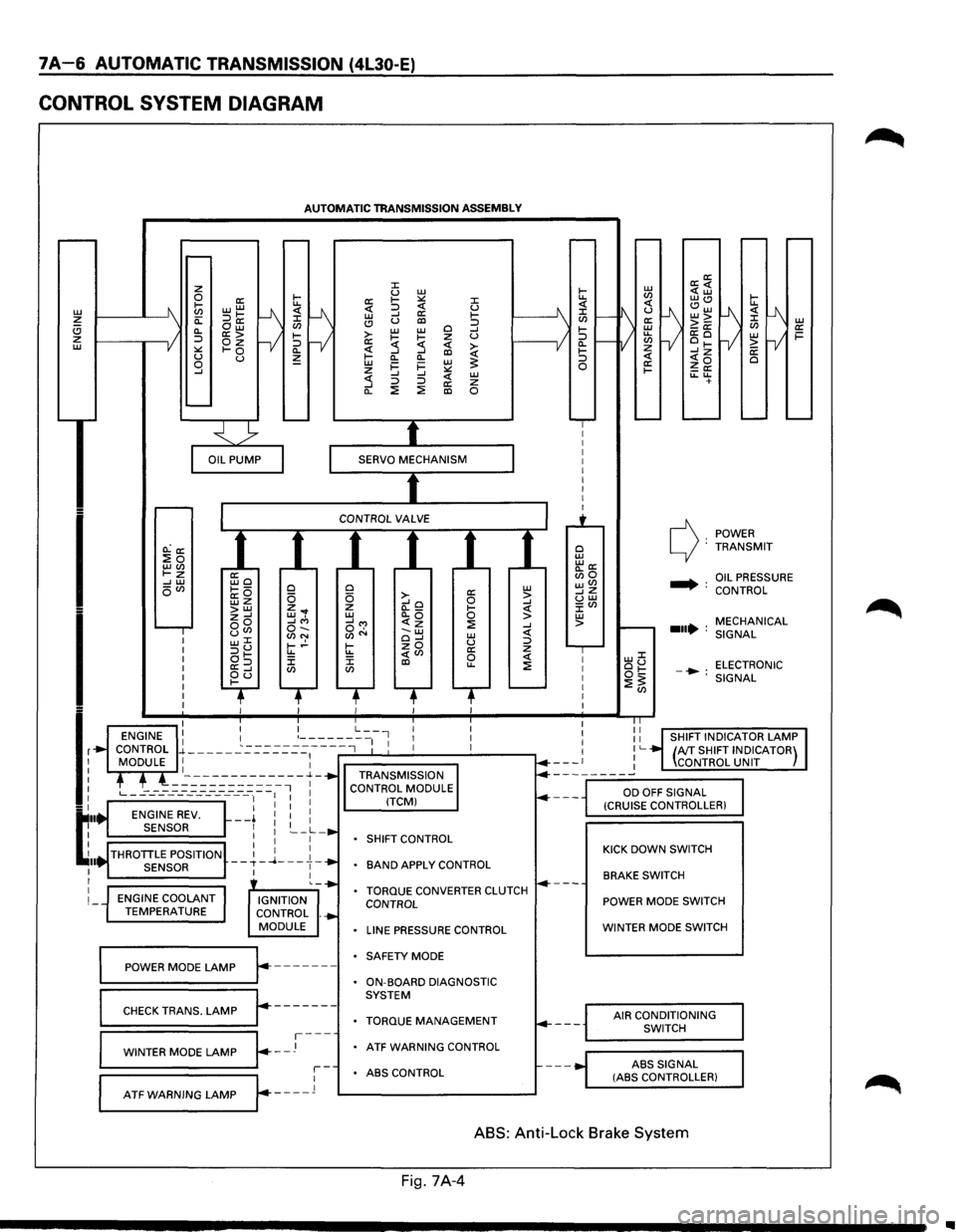
7A-6 AUTOMATIC TRANSMISSION (4L30-E)
CONTROL SYSTEM DIAGRAM
L1J ~ (!) z L1J
I
I
lr
t:··
~ .. I I
I
I
AUTOMATIC TRANSMISSION ASSEMBLY
O.:a: :Eo LLJ(J) t-z --' L1J oVl
ENGINE COOLANT TEMPERATURE
ffio ~---a:O wz >LLJ z--' oo uCJ> w::C :::>u at-a:=> ~d
0 0 z ... w, --'"' o-.. (J)N t-.!-u.. J: CJ)
IGNITION
CONTROL .
MODULE
~==PO=W==ER==M=O=D=E=L=A=M=P~r.-------
r-------CHECK TRANS. LAMP
~=W=IN=T=E=R=M=O=D=E=LA=M=P~~--J---
::c u L1J a: 1-:.:: ::c <( :::> <( u L1J --' a: 1-(!) u al :::> >-L1J L1J 0 --' 1-~ z u a: :5 <( ~ ~ --' al Cl.
Cl. L1J i=
i= L1J ~ z :.:: --' --' <( L1J :5 :::> :::> a: z Cl. ::!: ::!: al 0
0 a: L1J 0 >-0 > --'o --' z (l._ 1-<( L1J Cl.Q 0 > __,...,
SHIFT
CONTROL
BAND APPLY CONTROL
TORQUE CONVERTER CLUTCH CONTROL
LINE PRESSURE CONTROL
SAFETY MODE
ON-BOARD DIAGNOSTIC
SYSTEM
TORQUE MANAGEMENT
ATF WARNING CONTROL
r-ABS CONTROL
L--A-T_F_w_A_R_N_I_N_G_L_A_M_P_...Jr---_l 1---------------'
0 L1J "'a: Bio wVl __,z uw J:Vl L1J >
POWER c): TRANSMIT
.... : OIL PRESSURE
CONTROL
MECHANICAL
...• : SIGNAL
LLJJ: ou ELECTRONIC ot:: -•: ::!:~ SIGNAL
KICK DOWN SWITCH
BRAKE SWITCH
POWER MODE SWITCH
WINTER MODE SWITCH
AIR CONDITIONING
SWITCH
ABS
SIGNAL (ASS CONTROLLER)
ABS: Anti-Lock Brake System
Fig. 7A-4
..
Page 879 of 1928
1. SHIFT CONTROL
The transmission gear is shifted according to the
shift pattern selected by the driver.
~ In shifting gears, the gear ratio is controlled by the
ON/ OFF signal using the 1-2/3-4 shift solenoids and
the 2-3 shift solenoid.
2. BAND APPLY CONTROL
The band apply is controlled when in the 3-2
downshift (engine overrun prevention) and the
garage shift (shock control).
The band
apply solenoid is controlled by the signal
from the Pulse Width Modulation (PWM) to regulate
the
flow of the oil.
3. TORQUE CONVERTER CLUTCH CONTROL
The clutch ON/OFF is controlled by moving the
converter clutch valve through shifting Torque
Converter Clutch
(TCC) solenoid using the ON/OFF
signal.
4. LINE PRESSURE CONTROL
The throttle signal allows the current signal to be
sent
to the force motor. After receiving the current
signal, the force motor activates the pressure
regulator valve to regulate the line pressure.
5. ON-BOARD DIAGNOSTIC SYSTEM
Several malfunction displays can be stored in the
Transmission Control Module (TCM) memory, and
read
out of it afterward.
The serial data lines, which are required for the
testing of the final assembly and the coupling to
other electronic modules, can be regulated by this
function.
6 FAIL-SAFE MECHANISM
If there is a problem in the transmission system, the
TCM will go into a "backup" mode. The vehicle can
still be driven, but the driver must use the gear
lever to shift gears.
7. TORQUE MANAGEMENT CONTROL
The TCM sends the absolute spark advance signal
to the Engine Control Module (ECM) while the
transmission is being shifted, to control the engine
spark timing in compliance with the vehicle running
condition to reduce the shocks caused by the
change of speed.
8. ATF WARNING CONTROL
The oil temperature sensor detects the ATF oil
temperature to control the oil temperature warning,
TCC and the winter mode.
9. ABS CONTROL
When the select lever is at "L" or "R" range, a
signal is sent
to the ABS controller as one of the
ABS control conditions.
AUTOMATIC TRANSMISSION (4L30-E) 7A-7
Page 883 of 1928

AUTOMATIC TRANSMISSION (4L30-E) 7 A-11
FUNCTIONS OF INPUT /OUTPUT COMPONENTS
Components Function
Speed sensor
Senses rotation
of output shaft and feeds the data to Transmission
(fixed
to transmission (T/M)) Control Module (TCM)
Throttle Senses the extent of throttle valve opening and the speed of the throttle
position sensor (TPS) valve lever motion to open the valve and feeds the data to TCM (fed to
(fixed to engine)
Engine Control Module (ECM) also)
I
Brake Switch (SW) Senses whether the driver has pressed the brake pedal or not and feeds
N (fixed
to brake pedal) the
information to TCM
p Kick-down SW (fixed to Senses whether the driver has pushed the accelerator pedal fully or not
u accelerator pedal) and feeds the information to TCM
T Mode
SW (fixed to T/M) Senses the select lever position and feeds the information to TCM
s Power drive SW Senses whether the driver has selected the power mode and feeds the
I (fixed to front console) information to TCM
G T/M
oil temp. sensor
Senses the T/M oil temperature and feeds the data to TCM
N Engine
coolant Senses the engine cooling water temperature and feeds the data to TCM
A temperature
SW (feeds the signal from ECM)
L
Engine speed
signal Feeds the signals monitoring engine speed to TCM from Ignition Control
Module
(fed to ECM also)
Air conditioning Senses whether the air conditioner has been switched on or not and
information feeds the information
to TCM
On-board diagnostic
input By monitoring the Ground (GND), the location of failure is shown on the
T/M
monitor lamp ("CHECK TRANS") by flashing the diagnostic trouble
code
Winter switch
Senses whether the driver has selected the winter mode, and feeds the
(fixed
to front console) information to TCM
Cruise
controller Downshift takes place when Overdrive OFF signal is received from auto
(Overdrive
OFF signal) cruise control unit
Shift
solenoid Selects shift point and gear position suited to the vehicle running con-s 1-2/3-4, 2-3
dition on the basis of TCM output 0 Band apply solenoid
Controls oil flow suited to the vehicle running condition on the basis of L
E TCM output
0 N
Torque
Converter Controls clutch engagement/disengagement suited to the vehicle
u 0 Clutch solenoid running condition on the basis of TCM output
T I Force motor Adjusts the oil pump delivery pressure to line pressure suited to the p D
(Pressure regulator vehicle running condition on the basis of TCM output u valve) T
Power drive mode lamp
Informs the driver whether the vehicle is in power mode or not
s Winter drive mode lamp Informs the driver whether the vehicle is in winter mode or not
I T/M monitor lamp Informs the driver of failure in the system. It also displays the self diagnosis
G
("CHECK TRANS") code.
N Data Link Connector
(DLC) When connected with TECH 1 or tester, can communicate the data for A
L function
check, etc. (fed to ECM also). When TECH 1 is not connected, can
communicate the
signal for torque management with ECM.
Self-diagnosis connector
When short-circuited with the bipolar connector, the T/M monitor lamp
displays
a failure by code.
ATF warning
lamp Lights when ATF oil temperature rises.
ABS signal When the select lever is at "Reverse" or "L" range, sends a signal to the
ABS controller as one of the ABS control conditions.
Page 885 of 1928
AUTOMATIC TRANSMISSION (4L30-E) 7A-13
NORMAL OPERATION OF 1994-95 4L30-E TRANSMISSION
1. TORQUE CONVERTER CLUTCH (TCC)
APPLICATION CONDITIONS:
Engine coolant temperature must be above 70°C
(158°F).
Moreover, TCC is ON in 2nd gear during kick down
operation when engine coolant temperature is
above
70°C (158°F).
Also,
TCC is always ON in 2nd, 3rd & 4th gear when
transmission oil temperature is above 140°C
(284°F).
2. ATF WARNING LAMP
The ATF warning lamp will be constantly on (not
flashing) if the transmission oil temperature is
above
145°C (293°F).
The ATF warning lamp goes off again when the
transmission
oil temperature is below 125°C
(257°F).
3. SPECIAL SHIFT PATTERN WHEN THE
ENGINE IS COLD:
A special shift pattern is activated when the engine
coolant temperature is below 70°C (158°F). (3-4
shifts
for example are delayed for small throttle
openings and will occur a few MPH higher)
4. SHIFT ALTERATION WITH TECH1
DIAGNOSTIC TOOL CONNECTED:
Shifts will be harsh when TECH1 is connected to
TCM: Connection of TECH1 automatically forces
maximum line pressure during shifts only.
Page 895 of 1928
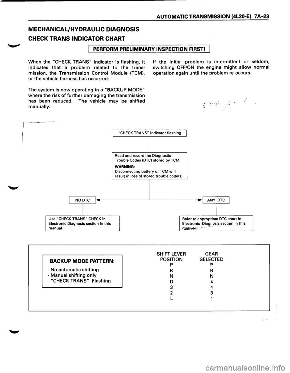
MECHANICAL/HYDRAULIC DIAGNOSIS
CHECK TRANS INDICATOR CHART
AUTOMATIC TRANSMISSION (4L30-E) 7 A-23
I PERFORM PRELIMINARY INSPECTION FIRST!
When the "CHECK TRANS" indicator is flashing, it
indicates that a problem related to the trans
mission, the Transmission Control
Module (TCM),
or the vehicle harness has occurred:
The system is
now operating in a "BACKUP MODE"
where the risk of further damaging the transmission
has been reduced. The vehicle may be shifted
manually.
If the initial problem is intermittent or seldom,
switching OFF/ON the engine might allow normal
operation again until the problem re-occurs.
I "CHECK TRANS" indicator flashing
I NO DTC I
I
Use "CHECK TRANS" CHECK in
Electronic Diagnosis section in this
manual
BACKUP MODE PATTERN:
-No automatic shifting
- Manual shifting only
-"CHECK TRANS" Flashing
Read and record the Diagnostic
Trouble Codes {DTCI stored by TCM.
WARNING: Disconnecting battery or TCM will result in loss of stored trouble code{s).
I ANY DTC J
I
Refer to appropriate DTC chart in
Electronic Diagnosis sectien in this
l'lUl,IUiah~ c " • •• "
SHIFT LEVER GEAR
POSITION p
R
N
D
3
2
L
SELECTED p
R
N
4
4
3
1
Page 921 of 1928
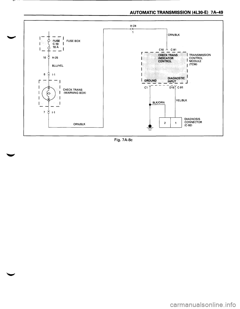
FUSE BOX
10 I H-25
BLU!YEL
6 t_l-1
r -~-~
I I CHECK TRANS I I (WARNING BOX)
I I
I
7 1-1
ORN/BLK
AUTOMATIC TRANSMISSION (4l30-E) 7 A-49
H-24
Fig. 7A-8c
ORN/BLK
C10 C-91
f - - -CHiCKTRANS--~ TRANSMISSION I tNOICAfiOR I CONTROL
I CONTROL MODULE I (TCM)
I I
I
I .. DIAGNOSTIC I _GROUNI',): _ _ t~U!_ ..:;;. .J
C1
BLK/ORN
D16 C-91
YEL!BLK
DIAGNOSIS
CONNECTOR
(C-92)
Page 1007 of 1928
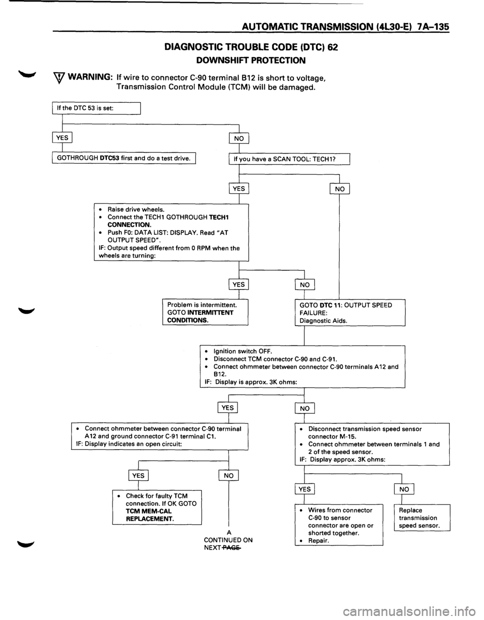
AUTOMATIC TRANSMISSION (4l30-E) 7 A .... 135
DIAGNOSTIC TROUBLE CODE (DTC) 62
DOWNSHIFT PROTECTION
W WARNING: If wire to connector C-90 terminal 812 is short to voltage,
Transmission Control Module (TCM) will be damaged.
GOTH ROUGH DTC53 first and do a test drive.
• Raise drive wheels.
•
Connect the TECH1 GOTHROUGH TECH1 CONNECTION.
•
Push FO: DATA LIST: DISPLAY. Read "AT OUTPUT SPEED".
IF: Output speed different from 0 RPM when the wheels are turning:
Problem is intermittent. GOTO INTERMITTENT
CONDITIONS.
•
Ignition switch OFF.
GOTO DTC 11: OUTPUT SPEED
FAILURE: Diagnostic Aids.
• Disconnect TCM connector C·90 and C-91. • Connect ohmmeter between connector C-90 terminals A 12 and
812.
IF: Display is approx. 3K ohms:
• Connect ohmmeter between connector C-90 terminal A12 and ground connector C-91 terminal C1. • Disconnect transmission speed sensor
connector M-15.
IF: Display indicates an open circuit:
• Check for faulty TCM
connection. If OK GOTO TCMMEM-CAL REPLACEMENT.
A
CONTINUED ON
NEXT-PAGe- •
Connect ohmmeter between terminals 1
and
2 of the speed sensor. IF: Display approx. 3K ohms:
• Wires from connector C-90 to sensor
connector are open or shorted together. • Repair.
Replace transmission
speed sensor.
Page 1013 of 1928
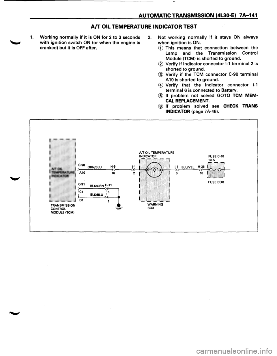
AUTOMATIC TRANSMISSION (4L30-E) 7A-141
A/T OIL TEMPERATURE INDICATOR TEST
1. Working normally if it is ON for 2 to 3 seconds
with ignition switch ON (or when the engine is
cranked)
but it is OFF after.
2. Not working normally if it stays ON always
when ignition is ON.
CD This means that connection between the
Lamp and the Transmission
Control
Module (TCM) is shorted to ground.
r~,··mm -,-,~
• , I
I
TRANSMISSION
CONTROL
MODULE (TCM)
@ Verify if Indicator connector 1-1 terminal 2 is
shorted
to ground.
@ Verify if the TCM connector C-90 terminal
A10 is shorted to ground.
@ Verify that the Indicator connector 1-1
terminal 6 is connected to Battery.
@ If problem not solved GOTO TCM MEM
CAL REPLACEMENT.
@ If problem solved see CHECK TRANS
INDICATOR
(page 7A-46).
AfT OIL TEMPERATURE INDICATOR ~-~--~I
C-90 ORNJBLU H-9 1~1 :·' ,.· . 'I 1-1 >-A-10--=.:..;.;_;:,=-~>>----<( · , . ' >• • _;__I ;:. 16 2 1 . • .i· ,..:., • 6
I ·•'I• ·. . , . . J
BLU!YEL
BLKJORND
BLK/IILU ~~
I II 1
I I
1_:1;_-:....... _]
WARNING BOX
FUSE BOX
Page 1014 of 1928
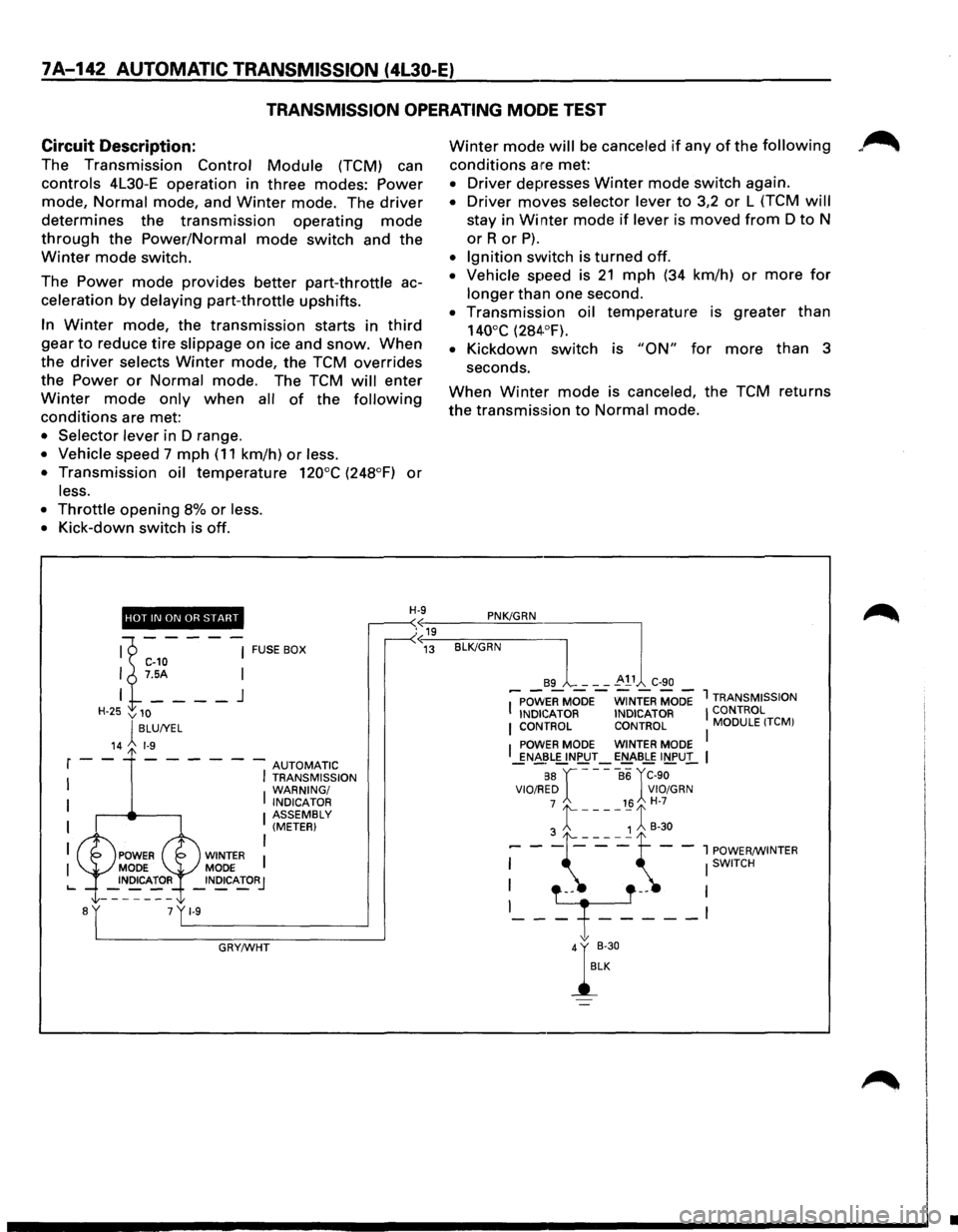
7A-142 AUTOMATIC TRANSMISSION (4l30-E)
TRANSMISSION OPERATING MODE TEST
Circuit
Description:
The Transmission Control Module (TCM) can
controls 4L30-E operation in three modes: Power
mode, Normal mode, and Winter mode. The driver
determines the transmission operating mode
through the Power/Normal mode switch and the
Winter mode switch.
The
Power mode provides better part-throttle ac
celeration
by delaying part-throttle upshifts.
In Winter mode, the transmission starts in third
gear to reduce tire slippage on ice and snow. When
the driver selects Winter mode, the TCM overrides
the
Power or Normal mode. The TCM will enter
Winter mode only when all of the following
conditions are met:
• Selector lever in D range.
• Vehicle speed 7 mph ( 11 km/h) or less.
•
Transmission oil temperature 120°C (248°F) or
less.
•
Throttle opening 8% or less.
•
Kick-down switch is off.
Winter mode will be canceled if any of the following
conditions are met:
• Driver depresses Winter mode switch again.
• Driver moves selector lever to 3,2 or L (TCM will
stay in Winter mode if lever is moved from D to N
orR or P).
• Ignition switch is turned off.
• Vehicle speed is 21 mph (34 km/h) or more for
longer than one second.
• Transmission oil temperature is greater than
140°C (284·°F).
• Kickdown switch is "ON" for more than 3
seconds.
When Winter mode is canceled, the TCM returns
the transmission
to Normal mode.
HOT IN ON OR START H-9 PNK/GRN
.«19 u
'1----~ FUSEBOX C-10 I 7.5A I
I
____ J
H-25 v 10
lBLUIYEL
14 1-9
r--- - - --AUTOMATIC
I
I I TRANSMISSION
WARNING/
I INDICATOR I ASSEMBLY (METER)
I
I WINTER MODE _INOICATORJ
GRY/WHT
«~13~-BL-K/~G-R-N----]
89 - - -~ 11 C-90
I~POW'ERMOOE-WiNTER MODE 1 TRANSMISSION
INDICATOR INDICATOR I CONTROL I CONTROL CONTROL MODULE !TCMI
I POWER MODE WINTER MODE I _gN~~L[.!NPUT-E!:::J£-BLE INPUl.. I
88 r ----86 rC-90 VIO/RED VIO/GRN 7 16 H-7
3 t ----~ 1 B-30
--\~~~--:~~~~NTER
-T---~
};
•