warning ISUZU TROOPER 1995 Service Manual
[x] Cancel search | Manufacturer: ISUZU, Model Year: 1995, Model line: TROOPER, Model: ISUZU TROOPER 1995Pages: 1928
Page 460 of 1928
5A4-50 4-WHEEL ANTILOCK BRAKE SYSTEM (ABS)
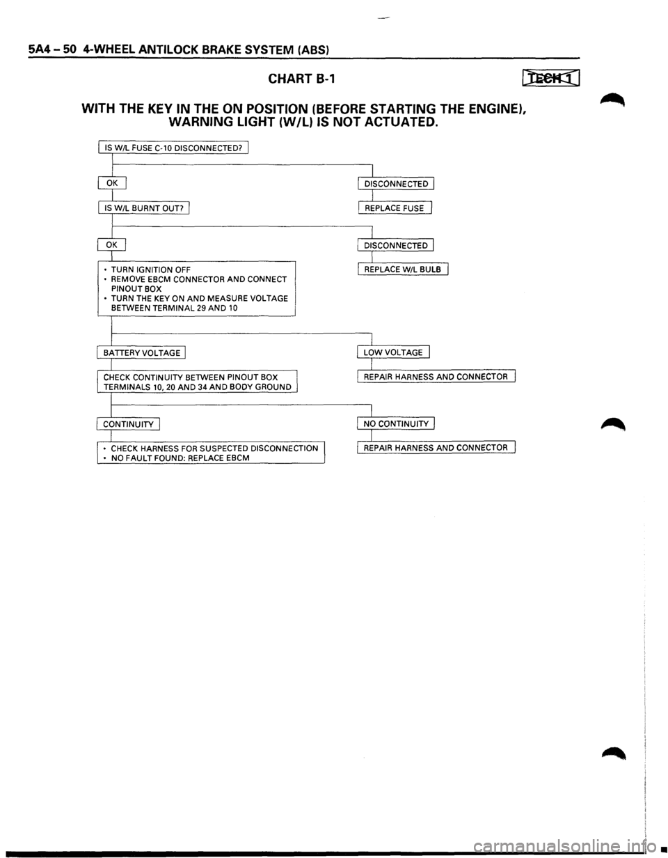
CHART B-1
WITH THE KEY IN THE ON POSITION (BEFORE STARTING THE ENGINE),
WARNING LIGHT
{W/L) IS NOT ACTUATED.
IS W/L FUSE C-10 DISCONNECTED? j
I
IS W/L BURNT OUT? I
I
• TURN IGNITION OFF
• REMOVE EBCM CONNECTOR AND CONNECT PINOUT BOX
• TURN THE KEY ON AND MEASURE VOLTAGE BETWEEN TERMINAL 29 AND 10
I
I
BATTERYVOLTAGE I
I
CHECK CONTINUITY BETWEEN PINOUT BOX I TERMINALS 10, 20 AND 34 AND BODY GROUND
l
I CONTINUITY I
I • CHECK HARNESS FOR SUSPECTED DISCONNECTION I • NO FAULT FOUND: REPLACE EBCM
I
I
DISCONNECTED I
I L REPLACE FUSE J
I L DISCONNECTED J
I I REPLACE W/L BULB I
I
I
LOWVOLTAGE I
I
I
REPAIR HARNESS AND CONNECTOR I
I
I
NO CONTINUITY I
I I REPAIR HARNESS AND CONNECTOR I
•
Page 462 of 1928
5A4-52 4-WHEEL ANTILOCK BRAKE SYSTEM (ABS)
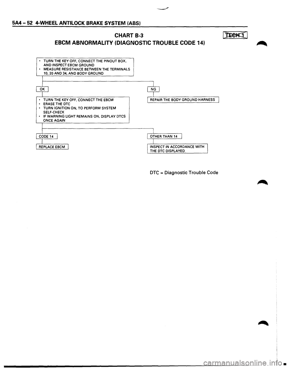
CHART B-3 ~I
EBCM ABNORMALITY (DIAGNOSTIC TROUBLE CODE 14)
• TURN THE KEY OFF, CONNECT THE PINOUT BOX. AND INSPECT EBCM GROUND
• MEASURE RESISTANCE BETWEEN THE TERMINALS
10, 20 AND 34, AND BODY GROUND
T
~ $
• TURN THE KEY OFF, CONNECT THE EBCM
• ERASE THE DTC I REPAIR THE BODY GROUND HARNESS I
• TURN IGNITION ON, TO PERFORM SYSTEM
SELF-CHECK
IF WARNING LIGHT REMAINS ON, DISPLAY DTCS
ONCE AGAIN
I
r I CODE14 I I OTHER THAN
14 I
I I
REPLACE EBCM I !INSPECT IN ACCORDANCE WITH I THE DTC DISPLAYED
DTC = Diagnostic Trouble Code
•
Page 474 of 1928
5A4 -64 4-WHEEL ANTILOCK BRAKE SYSTEM (ABS)
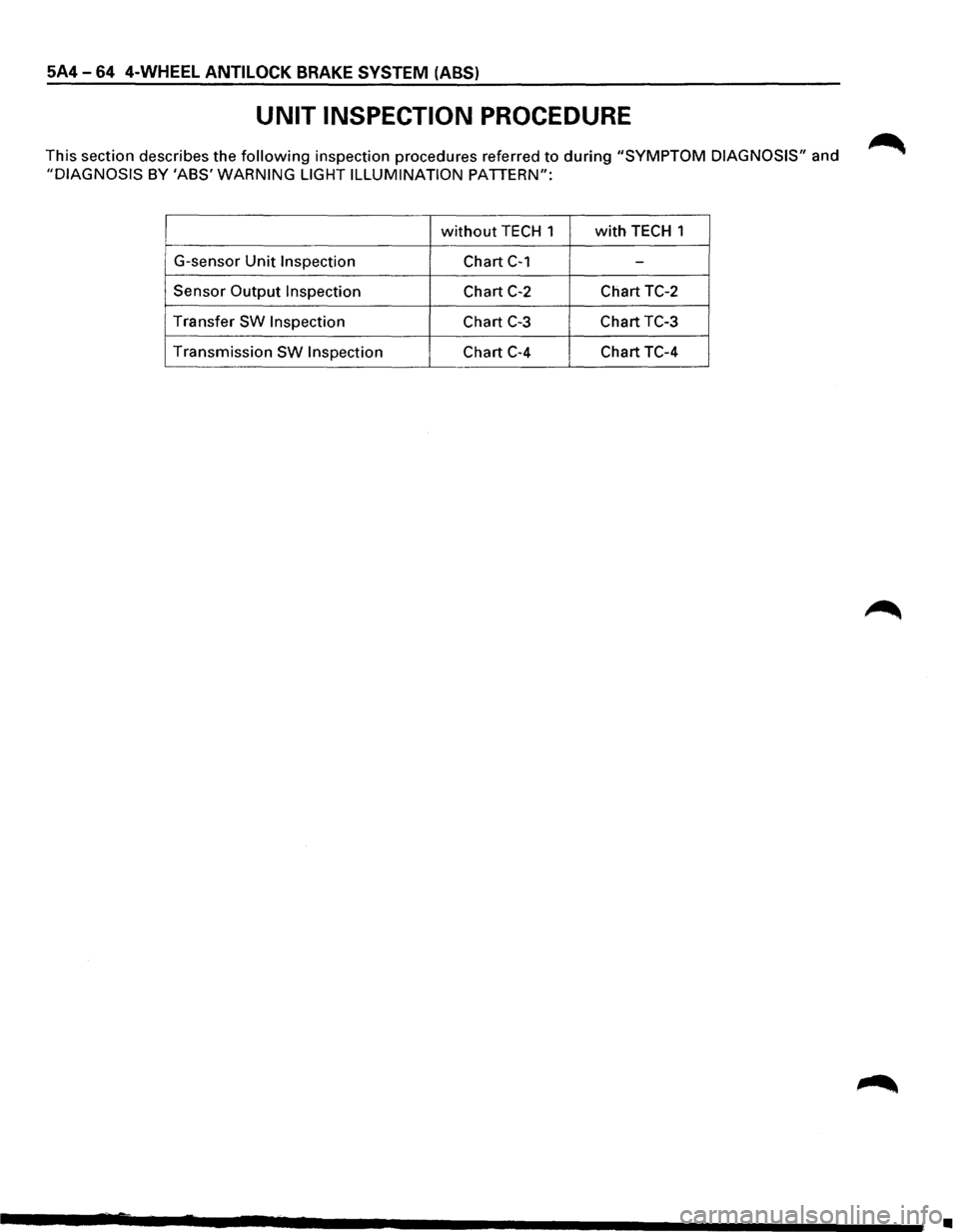
UNIT INSPECTION PROCEDURE
This section describes the following inspection procedures referred to during "SYMPTOM DIAGNOSIS" and
"DIAGNOSIS BY 'ABS' WARNING LIGHT ILLUMINATION PATTERN":
without TECH 1 with TECH 1
G-sensor
Unit Inspection Chart C-1 -
Sensor Output Inspection Chart C-2 Chart TC-2
Transfer
SW Inspection Chart C-3 Chart TC-3
Transmission
SW Inspection Chart C-4 Chart TC-4
•
Page 491 of 1928
PARKING BRAKES 5C-1
SECTION 5C
PARKING BRAKES
'\f7 CAUTION:
Yf All brake attaching fasteners are an important attaching part in that they could affect performance of vital
parts and systems, and/or could result in major repair expense. They must be replaced with one ofthe same
part number
or with and equivalent part if replacement becomes necessary. Do not use replacement parts of
lesser quality or substitute design. Torque values must be used as specified during reassembly to assure
proper retention
of these parts.
CONTENTS
General Description ..................... 5C-1
Operation . . . . . . . . . . . . . . . . . . . . . . . . . . . . . 5C-2
On-Vehicle Service
..................... 5C-3
Parking Brake Lever Replacement . .
. . . . .
5C-3
Parking Brake Front Cable . .
. . . . . . . . . . .
5C-4
Parking Brake Rear Cable . .
. . . . . . . . . . . .
5C-5
Parking Brake Lining Inspection ......... 5C-6
Parking Brake Rotor (Drum) Inspection ... 5C-6
Parking Brake Adjustment .............. 5C-7
Main Data and Specifications ............. 5C-8
General
Specifications ................. 5C-8
Torque Specifications ................. 5C-8
GENERAL DESCRIPTION
Pulling up the parking brake lever by hand will set the
parking brake.
Once pulled up, the lever is held by a
ratchet type
lock until it is released. The position of the
lever is transmitted through cable/lever systems to the
rear
wheels. These parts are designed to obtain
sufficient braking force
when parking on slopes. When
the parking brake is set,
or when the ignition SW is in
the
"ON" position, the brake warning light illuminates.
The rear wheel parking brake is a duo-servo brake
(mechanical inside expansion type) built in to the rear
disc brake. Parking brake adjustment is made through
the adjusting
hole (bored through back plate). Parking
brake
lever stroke should be adjusted to 6 or 7
notches. Refer
to "Parking Brake Adjustment" in
this Section.
Page 632 of 1928
68 - 4 ENGINE COOLING
ON-VEHICLE SERVICE
DRAINING AND REFILLING COOLING
SYSTEM
Before draining the cooling system, inspect the sys
tem and perform any necessary service to ensure that
it is clean, does not leak and is in proper working
order. The Engine Coolant (EC) level should be be
tween the "MIN" and "MAX" lines of reserve tank
when the engine is cold. If low, check for leakage and
add
EC up to the "MAX" line. There should not be any
excessive deposit of rust or scales around the radiator
cap
or radiator filler hole, and the EC should also be
free
from oil. Replace the EC if excessively dirty.
1. Completely drain the cooling system by opening
the drain petcock at the bottom of the radiator.
2. Remove the radiator cap.
W WARNING
To avoid the danger of being burned, do not
remove the cap while the engine and radiator
are still hot. Scalding fluid and steam can be
blown out under pressure.
3. Disconnect all hoses from the EC reserve tank.
Scrub and clean the inside of the reserve tank with
soap and water. Flush it well with clean water,
then drain it. Install the reserve tank and hoses.
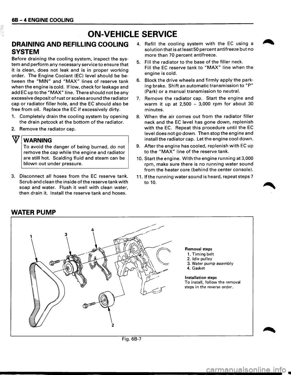
WATER PUMP
3
j
2
4. Refill the cooling system with the EC using a
solution that is at least 50 percent antifreeze but no
more than 70 percent antifreeze.
5. Fill the radiator to the base of the filler neck.
Fill the EC reserve tank to "MAX" line when the
engine is cold.
6. Block the drive wheels and firmly apply the park
ing brake.
Shift an automatic transmission to "P"
(Park) or a manual transmission to neutral.
7. Remove the radiator cap. Start the engine and
warm it up at 2,500 -3,000 rpm for about 30
minutes.
8. When the air comes out from the radiator filler
neck and the EC level has gone down, replenish
with the EC. Repeat this procedure until the EC
level does not go down. Then stop the engine and
install the radiator cap. Let the engine cool down.
9. After the engine has cooled, replenish with EC up
to the "MAX" line of the reserve tank.
10. Start the engine. With the engine running at 3,000
rpm, make sure there is no running water sound
from the heater core (behind the center console).
11. If the running water sound is heard, repeat steps 7
to 10.
Removal steps
1. Timing
belt 2. Idle pulley 3. Water pump assembly
4. Gasket
Installation steps To install, follow the removal steps in the reverse order.
Fig. 6B-7
•
Page 657 of 1928
ENGINE ELECTRICAL 601-3
ON-VEHICLE SERVICE
BATTERY CHARGING
Observe the following safety precautions when
charging the battery:
1. Never attempt to charge the battery when the
fluid level is below the lower level line on the
side
of the battery. In this case, the battery
must be replaced.
2. Pay close attention to the battery during the
charging procedure.
Battery charging
should be discontinued or the
rate
of charge reduced if the battery feels hot
to the touch.
Battery charging
should be discontinued or the
rate
of charge reduced if the battery begins to
gas or spew electrolyte from the vent holes.
3. In order to more easily view the hydrometer
blue dot or ring, it may be necessary to jiggle
or tilt the battery.
4. Battery temperature can have a great effect on
battery charging capacity.
5. The sealed battery used on this vehicle may be
either quick-charged or slow-charged in the
same manner
as other batteries.
Whichever method you decide
to use, be sure
that you
completely charge the battery. Never
partially charge the battery.
JUMP STARTING
JUMP STARTING WITH AN AUXILIARY
(BOOSTER)
BATTERY
W CAUTION:
Never push or tow the vehicle in an attempt to
start it.
Serious damage to the emission sys
tem as
well as other vehicle parts will result.
Treat both the discharged battery and the
booster battery
with great care when using
jumper cables. Carefully follow the jump start
ing procedure, being
careful at all times to
avoid sparking.
wwARNING:
Failure to carefully follow the jump starting
procedure
could result in the following:
1. Serious personal injury, particulaly to your
eyes.
2. Property damage from a battery explo
sion, battery acid, or an electrical fire.
3. Damage to the electronic components of
one or both vehicles particularly.
Never expose the battery to an open flame or elec
trical
spark. Gas generated by the battery may catch
fire
or explode.
Remove any rings, watches, or other jewelry before
working around the battery. Protect
your eyes by
wearing
an approved set of goggles.
Never allow battery fluid to come in contact with
your eyes or skin.
Never
allow battery fluid to come in contact with
fabrics or painted surfaces.
Battery
fluid is a highly corrosive acid.
Should battery fluid come in contact with your eyes,
skin, fabric, or a painted surface,
immediately and
thoroughly rinse the affected area with clean tap
water. Never
allow metal tools or jumper cables to come
in contact with the positive battery
terminal, or any
other
metal surface of the vehicle. This will protect
against a short circuit.
Always keep batteries out of the reach of young
children.
JUMP STARTING PROCEDURE
1. Set the vehicle parking brake.
If the vehicle is equipped with an automatic
transmission,
place the selector lever in the
"PARK" position.
If the vehicle is equipped with a manual trans
mission
place the shift lever in the "NEUTRAL"
position.
Turn
"OFF" the ignition.
Turn
"OFF" all lights and any other accessory
requiring
electrical power.
2. Look at the built-in hydrometer.
If the indication area of the built-in hydrometer
is
completely clear, do not try to jump start.
3. Attach the end of one jumper cable to the posi
tive
terminal of the booster battery.
Attach the other end
of the same cable to the
positive
terminal of the discharged battery.
Do not allow the vehicles to touch each other.
This
will cause a ground connection, effectively
neutralizing
the charging procedure.
Be sure that the booster battery has a 12 volt
rating.
4. Attach one end of the remaining cable to the
negative
terminal of the booster battery.
Attach the other end
of the same cable to a
solid engine ground (such as the air condition
ing compressor bracket or the generator
mounting bracket)
of the vehicle with the dis
charged battery.
This ground connection must be at
least 450
mm (18 in) from the battery of the vehicle
whose battery is being charged.
Page 658 of 1928
601-4 ENGINE ELECTRICAL
'IT7 WARNING:
'if Never attach the end of the jumper cable
directly
to the negative terminal of the dead
battery.
5. Start the engine of the vehicle with the good
battery.
Make sure that
all unnecessary electrical acces
sories have been turned
"OFF".
6. Start the engine of the vehicle with the dead
battery.
7. To remove the jumper cables, follow the above
directions in the reverse order.
Be sure to first disconnect the negative cable
from the vehicle with the discharged battery.
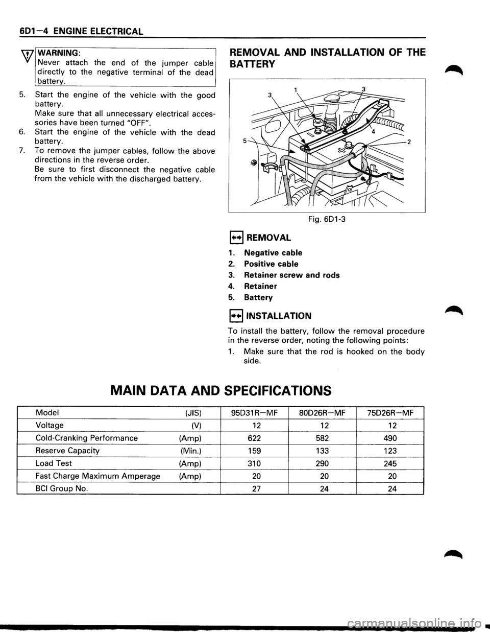
REMOVAL AND INSTALLATION OF THE
BATTERY
5
Fig. 601-3
1+•1 REMOVAL
1. Negative cable
2. Positive cable
3. Retainer screw and rods
4. Retainer
5. Battery
I••IINSTALLATION
To install the battery, follow the removal procedure
in the reverse order, noting the
following points:
1. Make sure that the rod is hooked on the body
side.
MAIN DATA AND SPECIFICATIONS
Model
(JIS) 95D31R-MF 80D26R-MF 75D26R-MF
Voltage (V) 12 12 12
Cold-Cranking Performance (Amp)
622 582 490
Reserve Capacity
(Min.)
159 133
123
Load Test
(Amp)
310 290 245
Fast Charge
Maximum Amperage
(Amp) 20 20 20
BCI Group No. 27 24 24
..
Page 679 of 1928
CHARGING SYSTEM 603 -3
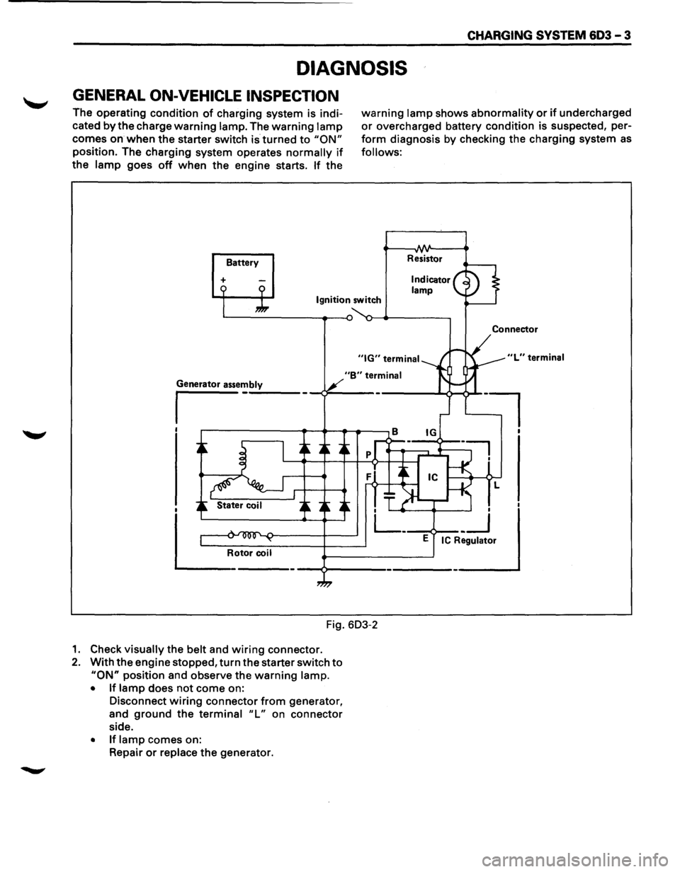
DIAGNOSIS
GENERAL ON-VEHICLE INSPECTION
The operating condition of charging system is indi
cated
by the charge warning lamp. The warning lamp
comes on when the starter switch is turned to "ON"
position. The charging system operates normally if
the lamp goes off when the engine starts. If the
Battery
+
warning lamp shows abnormality or if undercharged
or overcharged battery condition is suspected, per
form diagnosis by checking the charging system as
follows:
Resistor
Ignition switch
"B" terminal
Fig. 603-2
1. Check visually the belt and wiring connector.
2. With the engine stopped, turn the starter switch to
"ON" position and observe the warning lamp.
• If lamp does not come on:
Disconnect
wiring connector from generator,
and
ground the terminal "L" on connector
side.
• If lamp comes on:
Repair
or replace the generator.
Connector
"L" terminal
l
Page 687 of 1928
-
2) Pulley nut
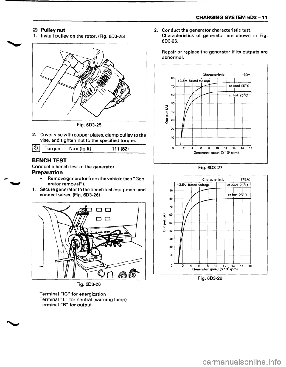
1. Install pulley on the rotor. (Fig. 603-25)
Fig. 603-25
2. Cover vise with copper plates, clamp pulley to the
vise, and tighten nut to the specified torque.
~~~Torque N-m(lb.ft) 111(82)
BENCH TEST
Conduct a bench test of the generator.
Preparation
• Remove generatorfrom the vehicle (see "Gen
erator removal").
1. Secure generator to the bench test equipment and
connect wires. (Fig. 603-26)
DO
DO
Fig. 603-26
Terminal "IG" for energization
Terminal "L" for neutral (warning lamp)
Terminal
"B" for output
CHARGING SYSTEM 603 -11
2. Conduct the generator characteristic test.
Characteristics
of generator are shown in Fig.
603-26.
Repair
or replace the generator if its outputs are
abnormal.
Characteristic (60A) 80 13.5V Based voltage
70
60
50
5 ... 40 "' c. ... 30 "'
......... r-at lool ~5°C
v ,........
/, /
at hot 25°C-
Iff_
f/
0
20
10
J 0 2 4 6 8 10 12 14 16 18
Generator speed (X 103 rpm)
Fig. 603-27
Characteristic (75A)
13.5V Based
voltage at cooi25°C
90
80
70
5 60
...
"' 50 c. ...
v at hot 25°C
I / ~
l/ /
r/
I
"' 0 40
30
20
10
0 2
4 6
8
10 12 14 16
18
Generator speed (X103 rpm)
Fig. 603-28
Page 876 of 1928
•
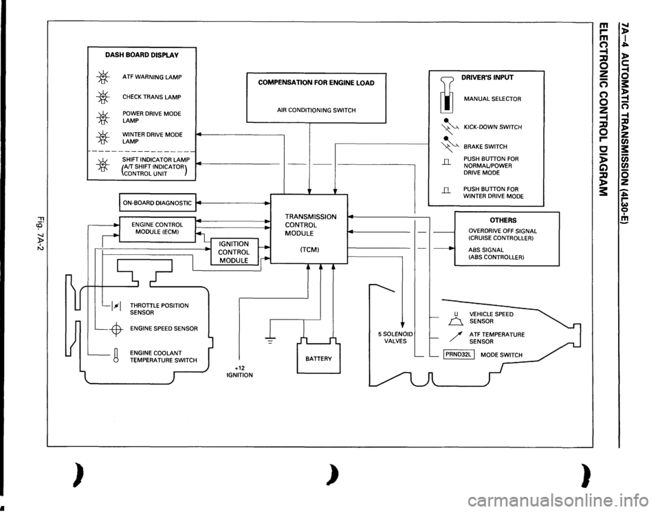
"'Tl c3' -..J )> I "'
~ )
DASH
BOARD
DISPLA
V
*
*
*
*
ATF
WARNING
LAMP
CHECK
TRANS
LAMP
POWER DRIVE MODE LAMP WINTER DRIVE MODE LAMP
~----------------
SHIFT INDICATOR
LAMP
COMPENSATION
FOR
ENGINE
LOAD
AIR CONDITIONING SWITCH
TI
DRIVER'S
INPUT
liJ
MANUAL
SELECTOR
~
KICK-DOWN SWITCH
" ~
BRAKE
SWITCH
*
(AfT
SHIFT INDICATOR)
CONTROL
UNIT
---
' ---
I-------------,
il
PUSH BUTTON
FOR
NORMALJPOWER
DRIVE MODE
ON-BOARD DIAGNOSTIC
j4
.. ,
..
l__l--1 L_-$-L_g
ENGINE CONTROL
MODULE
(ECM)
_ IGNITION
CONTROL
I
MODULE
i
THROTTLE POSITION
SENSOR
ENGINE SPEED SENSOR
l
I
I -
ENGINE COOLANT TEMPERATU~,_.TCH
)
I +12 IGNITION
• •
TRANSMISSION
CONTROL MODULE
(TCM)
j
L I
BATTERY
)
--
~
'
5SOLENOID VALVES
il
-·----·
___.
u
PUSH BUTTON
FOR
WINTER DRIVE MODE
OTHERS
OVERDRIVE
OFF
SIGNAL
(CRUISE CONTROLLER)
ABS
SIGNAL
(ABS CONTROLLER)
f.-
n_
VEHICLE SPEED
SENSOR
f-
/
ATF TEMPERATURE SENSOR
L__ L__
[PRNDJ2L
I MODE SWITCH
-
m
.....
r-
)>
m
I
(")
..;=...
-t
)>
;::g 0
c:
2
-1
-
0
(")
s:
(")
~
0
-
2
n
-t
-1
;::g
:a
0
)> z
r-
en
c
s:
:;
(i)
C)
en
~
0 z
3:
-..;=... r-w 0 I !!!
)