ISUZU TROOPER 1995 Workshop Manual
Manufacturer: ISUZU, Model Year: 1995, Model line: TROOPER, Model: ISUZU TROOPER 1995Pages: 1928
Page 611 of 1928
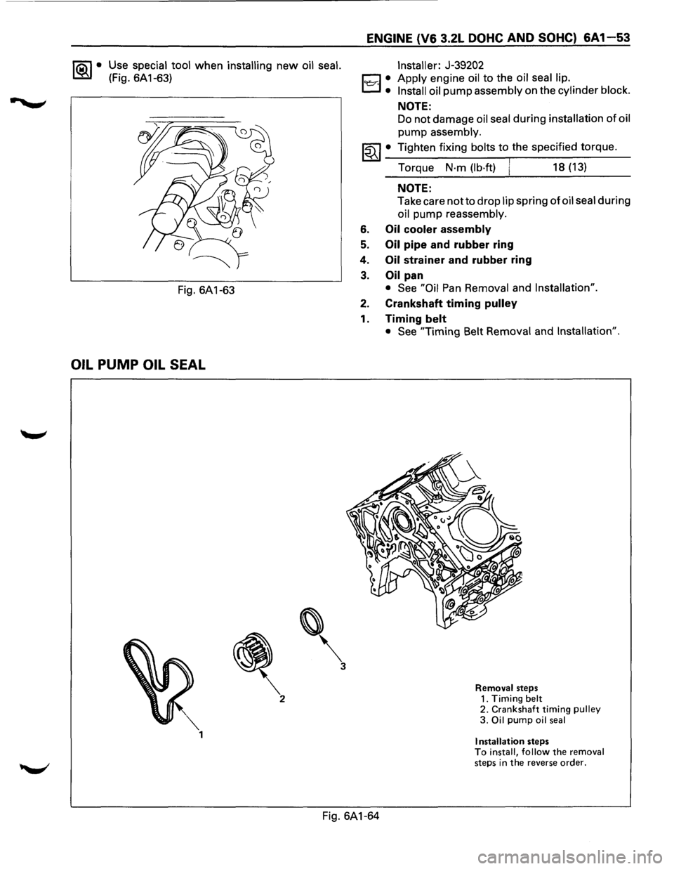
1®.1• Use special tool when installing new oil seal.
(Fig. 6A 1-63)
Fig. 6A1-63
OIL PUMP OIL SEAL
'
3
ENGINE (V6 3.2L DOHC AND SOHC) 6A 1-53
l'l::r.l :
Installer: J-39202
Apply
engine oil to the oil seal lip.
Install oil
pump assembly on the cylinder block.
NOTE:
Do not damage oil seal during installation of oil
pump assembly.
~~~· Tighten fixing bolts to the specified torque.
Torque
N·m (lb·ft) 18 (13)
NOTE:
Take care notto drop lip spring of oil seal during
oil pump reassembly.
6. Oil cooler assembly
5. Oil pipe and rubber ring
4.
Oil strainer and rubber ring
3. Oil pan
• See "Oil Pan Removal and Installation".
2. Crankshaft timing pulley
1. Timing belt
• See "Timing Belt Removal and Installation".
Removal steps 1. Timing belt 2. Crankshaft timing pulley 3. Oil pump oil seal
Installation steps To install, follow the removal steps in the reverse order.
Fig. 6A1-64
Page 612 of 1928
6A1-54 ENGINE (V6 3.2L DOHC AND SOHC)
1••1 REMOVAL
1. Timing belt
• See "Timing Belt Removal and Installation".
2. Crankshaft timing pulley
3. Oil pump oil seal
• Remove oil seal using a sealer puller.
NOTE:
Take care not to damage sealing surfaces of oil
pump and crankshaft when removing oil seal.
1••1 INSTALLATION
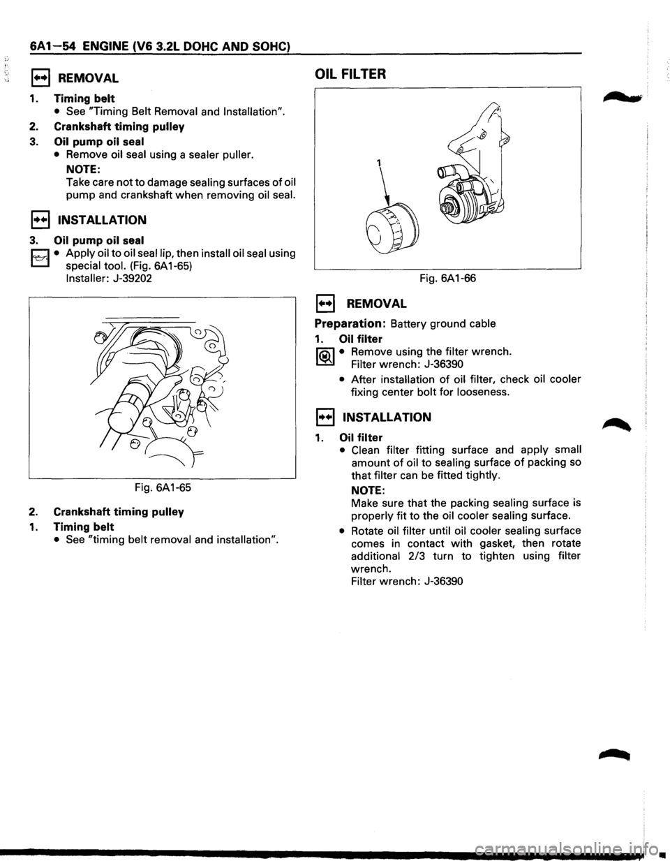
3. Oil pump oil seal
Cl • Apply oil to oil seal lip, then install oil seal using
L..:::::.l special tool. (Fig. 6A1-65)
Installer: J-39202
Fig. 6A1-65
2. Crankshaft timing pulley
1. Timing belt
• See "timing belt removal and installation".
OIL FILTER
1
Fig. 6A1-66
E) REMOVAL
Preparation: Battery ground cable
1. Oil filter
lia\l • Remove using the filter wrench.
~ Filter wrench: J-36390
• After installation of oil filter, check oil cooler
fixing center bolt for looseness.
1••1 INSTALLATION
1. Oil filter
• Clean filter fitting surface and apply small
amount of oil to sealing surface of packing so
that filter can be fitted tightly.
NOTE:
Make sure that the packing sealing surface is
properly fit to the oil cooler sealing surface.
• Rotate oil filter until oil cooler sealing surface
comes in contact
with gasket, then rotate
additional 2/3 turn to tighten using filter
wrench.
Filter wrench: J-36390
, ...
Page 613 of 1928
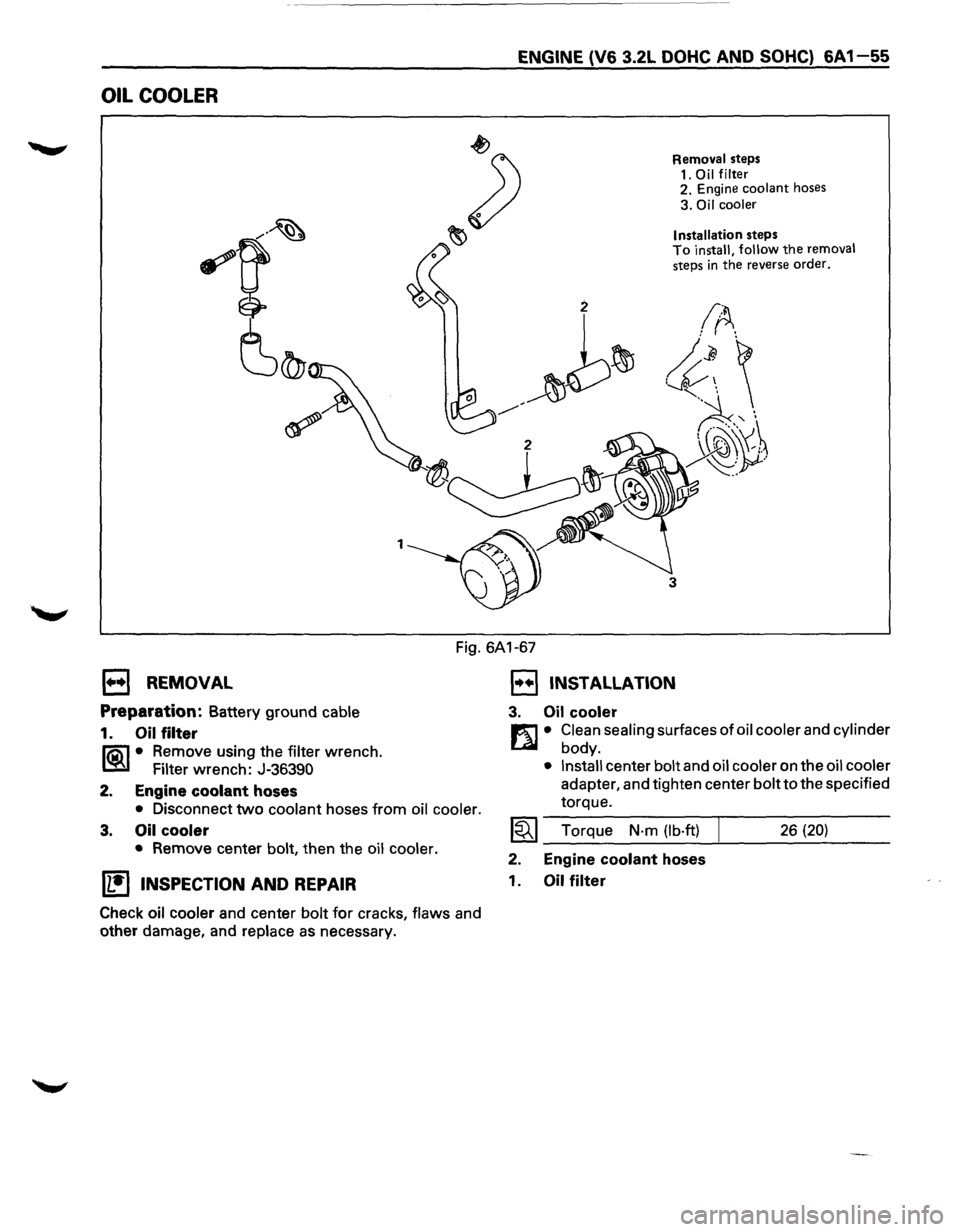
OIL COOLER
1
ENGINE (V6 3.2L DOHC AND SOHC) 6A 1-55
Removal steps
1.
Oil filter 2. Engine coolant hoses
3. Oil cooler
Installation
steps To install, follow the removal steps in the reverse order.
3
Fig. 6A1-67
1••1 REMOVAL
Preparation: Battery ground cable
1. Oil filter
li5\1 • Remove using the filter wrench.
~ Filter wrench: J-36390
2. Engine
coolant hoses
• Disconnect two coolant hoses from oil cooler.
3. Oil cooler
• Remove center bolt, then the oil cooler.
U!)INSPECTION AND REPAIR
Check oil cooler and center bolt for cracks, flaws and
other damage, and
replace as necessary.
1••1 INSTALLATION
3. Oil cooler
m • Clean sealing surfaces of oil cooler and cylinder
L41 body.
• Install center bolt and oil cooler on the oil cooler
adapter, and tighten center bolt to the specified
torque.
~~~ Torque N·m (lb·ft) 26 (20)
2. Engine coolant hoses
1.
Oil filter
Page 614 of 1928
 ~-;_' ;_\
~: PISTON, PISTON RINGS AND CONNECTING ROD
5
6
2
Removal steps 1. Cylinder head
2. Oil pan
3. Oil pipe and rubber ring
4. Oil strainer an")
6A 1-56 ENGINE (V6 3.2L DOHC AND SOHC) ~-;_' ;_\'
~: PISTON, PISTON RINGS AND CONNECTING ROD
5
6
2
Removal steps 1. Cylinder head
2. Oil pan
3. Oil pipe and rubber ring
4. Oil strainer and rubber ring
5.
Oil gallery
6. Piston
and connecting rod assembly
Installation steps
To install, follow the removal
steps in the reverse order.
Fig. 6A1-68
1••1 REMOVAL
1. Cylinder head
• See "Cylinder Head Removal and Installation".
2. Oil pan
• See "Oil Pan Removal and Installation".
3. Oil pipe and rubber ring
4. Oil strainer and rubber ring
5.
Oil gallery
6. Piston and connecting rod assembly
• Before removing the bearing cap, remove
carbon on the top
of cylinder bore.
• Push piston and connecting rod out from the
top of cylinder bore.
1••1 INSTALLATION
6. Piston and connecting rod assembly
19:::7;1• Apply engine oil to cylinder bore, connecting
rod bearings and crank pins.
• When installing the piston, its front mark must
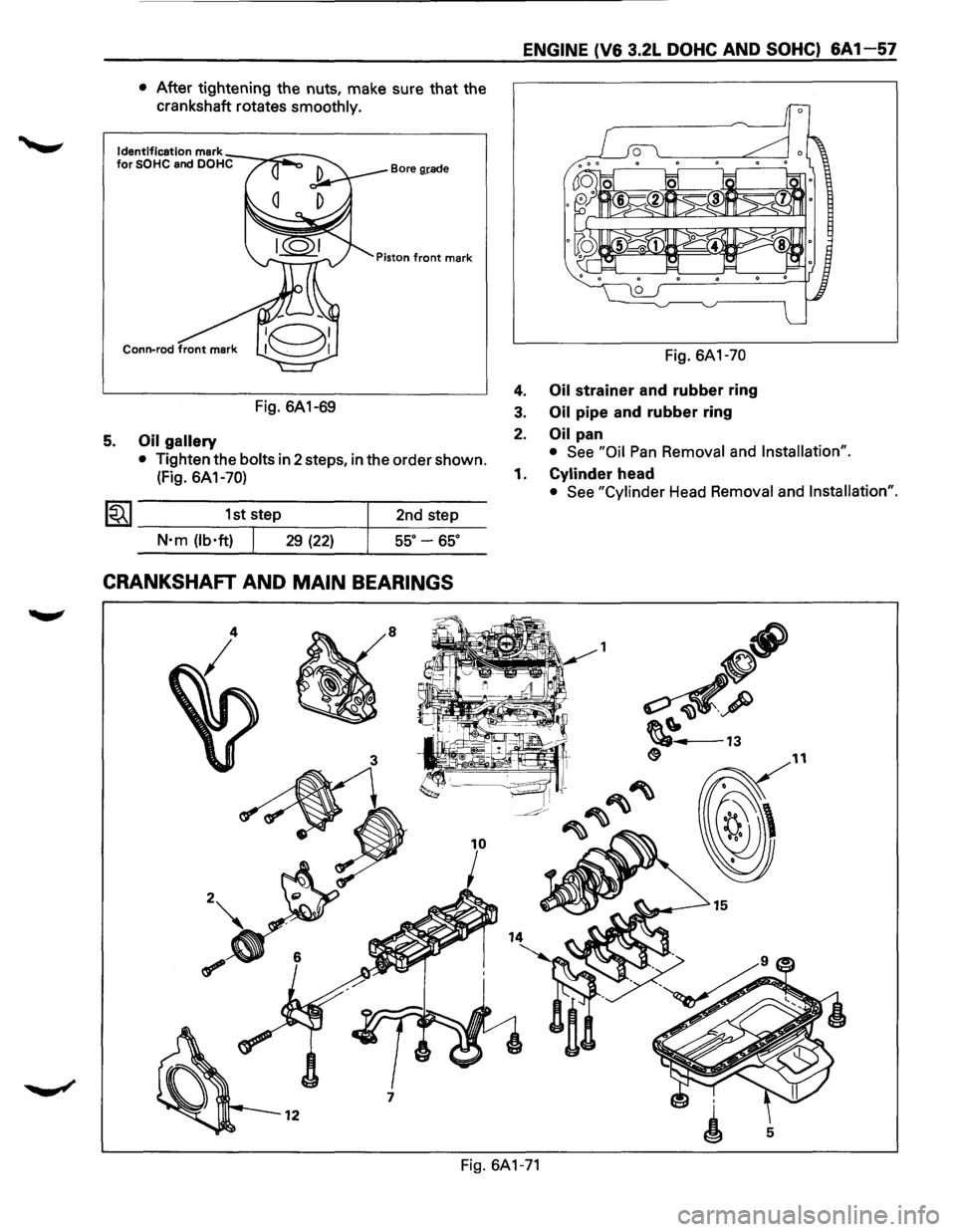
face the engine front side. (Fig. 6A 1-69)
• The bearing cap number must be same as
connecting rod number.
1~1 • Apply engine oil to the thread and sealing
surface
of each nut.
~~~· Tighten nuts to the specified torque.
Torque
N·m (lb·ft) 54 (40)
NOTE:
• Do not apply engine oil to the bearing back
faces and connecting rod bearing fitting
surfaces.
•
Page 615 of 1928
5.
• After tightening the nuts, make sure that the
crankshaft rotates
smoothly.
Bore g,rade
Fig. 6A1-69
Oil gallery
• Tighten the bolts in 2 steps, in the order shown.
(Fig. 6A1-70)
1~1 _________ 1_st_s,t_e~p ________ ~_2_n_d_s_t_ep~---
N·m (lb·ft) 29 (22) ss·-ss·
CRANKSHAFT AND MAIN BEARINGS
~·
3
7
ENGINE (V6 3.2L DOHC AND SOHC) 6A 1-57
4.
3.
2.
1.
Fig. 6A1-70
Oil strainer and rubber ring
Oil pipe and rubber ring
Oil pan
• See "Oil Pan Removal and Installation".
Cylinder head
• See "Cylinder Head Removal and Installation".
11
15
5
Fig. 6A1-71
Page 616 of 1928
,): .. • T·
6A 1-58 ENGINE (V6 3.2L DOHC AND SOHC)
EJ REMOVAL
1. Engine assembly
• See "Engine Assembly
Removal and Instal-
lation".
2. Crankshaft pulley
3. Timing belt cover
4. Timing belt
5. Oil pan
6. Oil pipe and rubber ring
7. Oil strainer and rubber ring
8. Oil pump assembly
9. Crankcase side bolts
10.
Oil gallery
11. Flywheel
12.
Rear oil seal retainers
13.
Connecting rod caps
14.
Crankshaft main bearing caps
15.
Crankshaft and main bearings
1•+1 INSTALLATION
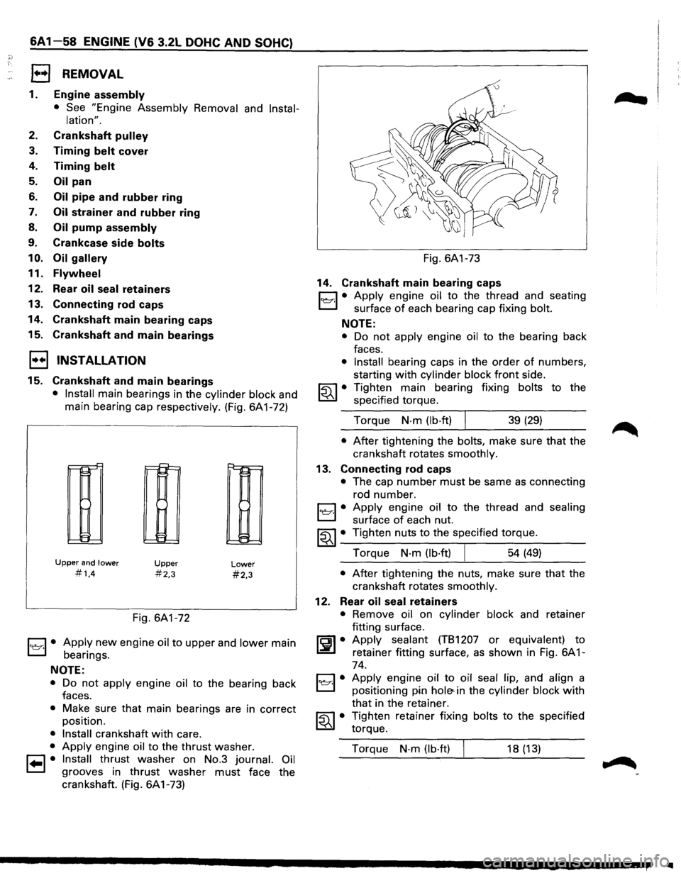
15. Crankshaft and main bearings
• Install main bearings in the cylinder block and
main bearing cap respectively. (Fig. 6A1-72)
r-r-'
II-
!:=
Upper and lower
#1,4
~
!::
E:
Upper
#2,3
Fig. 6A1-72
Lower
#2,3
1~1· Apply new engine oil to upper and lower main
bearings.
NOTE:
• Do not apply engine oil to the bearing back
faces.
• Make sure that main bearings are in correct
position.
• Install crankshaft with care.
• Apply engine oil to the thrust washer.
1•1• Install thrust washer on No.3 journal. Oil
grooves in thrust washer must face the
crankshaft. (Fig. 6A1-73) Fig.
6A1-73
14. Crankshaft main bearing caps
C1 • Apply engine oil to the thread and seating
L:::J surface of each bearing cap fixing bolt.
NOTE:
• Do not apply engine oil to the bearing back
faces.
• Install bearing caps in the order of numbers,
starting
with cylinder block front side.
~~~ • Tighten main bearing fixing bolts to the
specified torque.
Torque
N·m (lb·ft) I 39 (29)
• After tightening the bolts, make sure that the
crankshaft rotates
smoothly.
13. Connecting rod caps
• The cap number must be same as connecting
rod number.
1~1· Apply engine oil to the thread and sealing
surface of each nut.
~~~· Tighten nuts to the specified torque.
Torque
N·m (lb·ft) 54 (49)
• After tightening the nuts, make sure that the
crankshaft rotates
smoothly.
12. Rear oil seal retainers
• Remove oil on cylinder block and retainer
fitting surface.
~~~· Apply sealant (TB1207 or equivalent) to
retainer fitting surface, as shown in Fig. 6A 1-
74.
C1 • Apply engine oil to oil seal lip, and align a
El positioning pin hole< in the cylinder block with
that in the retainer.
~~~· Tighten retainer fixing bolts to the specified
torque.
Torque
N·m (lb·ft) 18 (13)
IIIII
Page 617 of 1928
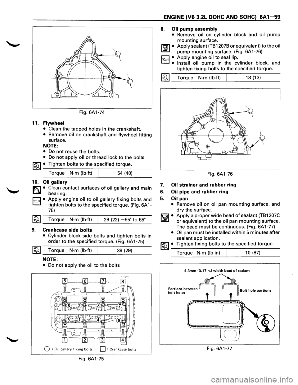
Fig. 6A1-74
11. Flywheel
• Clean the tapped holes in the crankshaft.
• Remove oil on crankshaft and flywheel fitting
surface.
NOTE:
• Do not reuse the bolts.
•
Do not apply oil or thread lock to the bolts.
~~~ • Tighten bolts to the specified torque.
Torque
N-m (lb·ft) 54 (40)
10. Oil gallery
m • Clean contact surfaces of oil gallery and main
~ bearing.
D • Apply engine oil to oil gallery fixing bolts and
L:::J tighten bolts to the specified torque. (Fig. 6A 1-
75)
~~~ Torque N·m (lb·ft) 29 (22) -55° to 65°
9. Crankcase side bolts
• Cylinder block side bolts and tighten bolts in
order
to the specified torque. (Fig. 6A 1-75)
~~~ Torque N·m (lb·ft) 39 (29)
NOTE:
• Do not apply the oil to the bolts
0 :Oil gallery fixing bolts 0: Crankcase bolts
Fig. 6A1-75
ENGINE (V6 3.2L DOHC AND SOHC) 6A1-59
8. Oil pump assembly
• Remove oil on cylinder block and oil pump
mounting surface.
ll:JI• Apply sealant (TB12078 or equivalent) to the oil
pump mounting surface. (Fig. 6A1-76)
19Y·I •. Apply engine oil to seal lip.
Install oil
pump in the cylinder block, and
tighten fixing
bolts to the specified torque.
1~1 Torque N·m (lb·ft)
Fig. 6A1-76
7. Oil strainer and rubber ring
6. Oil pipe and rubber ring
5. Oil pan
18 (13)
• Remove oil on oil pan mounting surface, and
dry the surface.
~~~· Apply a proper wide bead of sealant (TB1207C
or equivalent) to the oil pan mounting surface.
The bead
must be continuous. (Fig. 6A1-77)
• Oil pan must be installed within 5 minutes after
sealant application.
~~~· Tighten fixing bolts to the specified torque.
Torque
N·m (lb·in) 10 (87)
4.3mm (0.17in.) width bead of sealant
Portions between bolt holes I Bolt hole portions
D
Fig. 6A1-77
Page 618 of 1928
6A1-60 ENGINE (V6 3.2L DOHC AND SOHC}
4. Timing belt
• See "Timing Belt Removal and Installation".
3. Timing belt cover
2. Crankshaft pulley
~ • Using special tool J-8614-01, hold the
~ crankshaft pulley.
~~~· Tighten center bolt to the specified torque.
Torque
N·m (lb·ft) 167 (123)
1. Engine assembly
• See "Engine Assembly Removal and Instal
lation".
REAR OIL SEAL
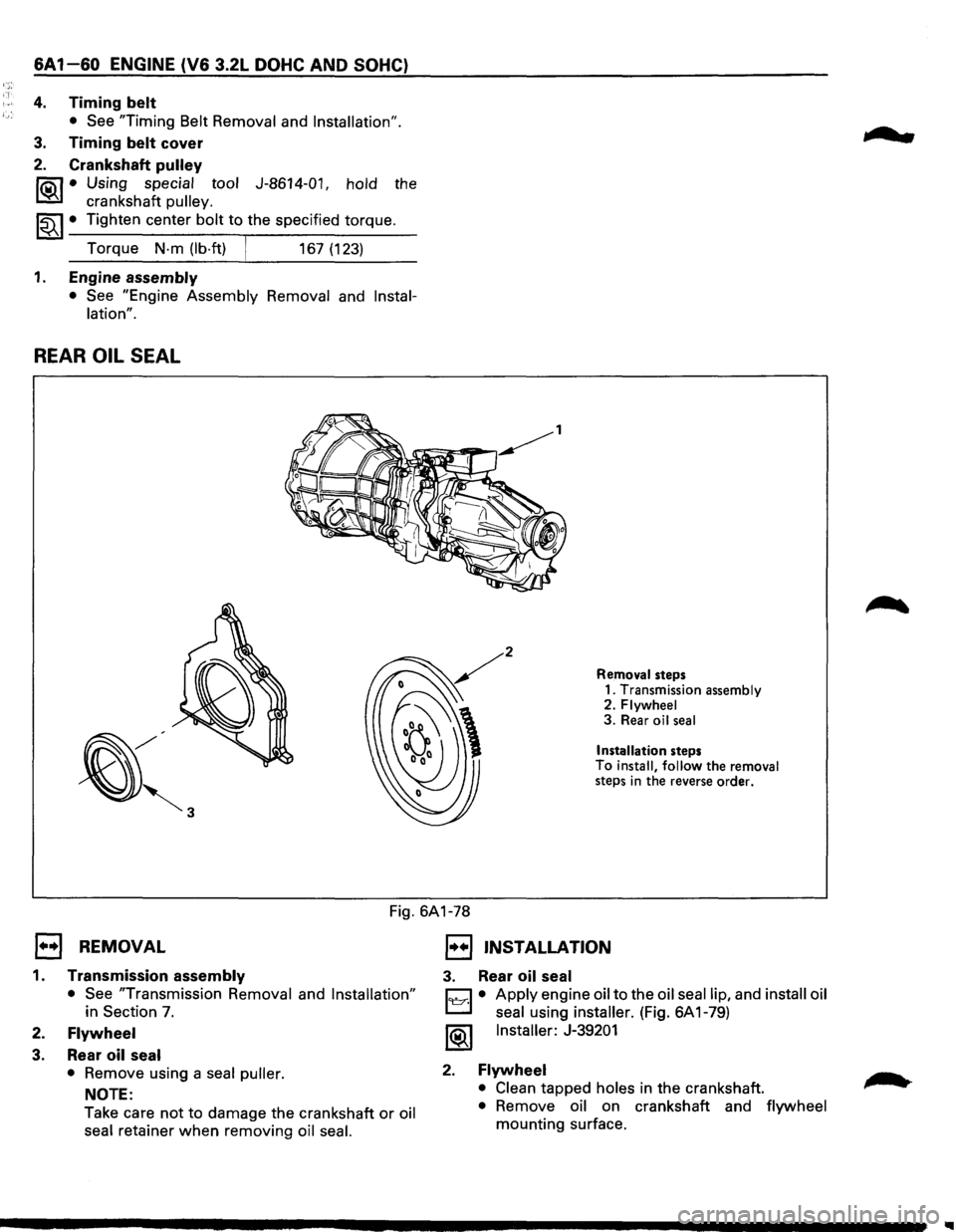
Removal steps
1. Transmission assembly
2.
Flywheel 3. Rear oil seal
Installation steps To install, follow the removal
steps in the reverse order.
Fig. 6A1-78
E) REMOVAL
1. Transmission assembly
• See "Transmission Removal and Installation"
in Section 7.
2. Flywheel
3. Rear oil seal
•
Remove using a seal puller.
NOTE:
Take care
not to damage the crankshaft or oil
seal retainer
when removing oil seal.
1••1 INSTALLATION
3. Rear oil seal
C1 • Apply engine oil to the oil seal lip, and install oil
L:::l seal using installer. (Fig. 6A 1-79)
1®1 Installer: J-39201
2. Flywheel
• Clean tapped holes in the crankshaft.
• Remove oil on crankshaft and flywheel
mounting surface.
...
Page 619 of 1928
NOTE:
• Do not reuse the bolts.
•
Do not apply oil or thread lock to the bolts.
~~~ • Tighten bolts to the specified torque.
Torque
N·m (lb·ft) 54 (40)
1. Transmission
• See "Transmission Removal and Installation"
in Section 7.
Fig. 6A1-79
ENGINE ASSEMBL V
ENGINE (V6 3.2L DOHC AND SOHC) 6A 1-61
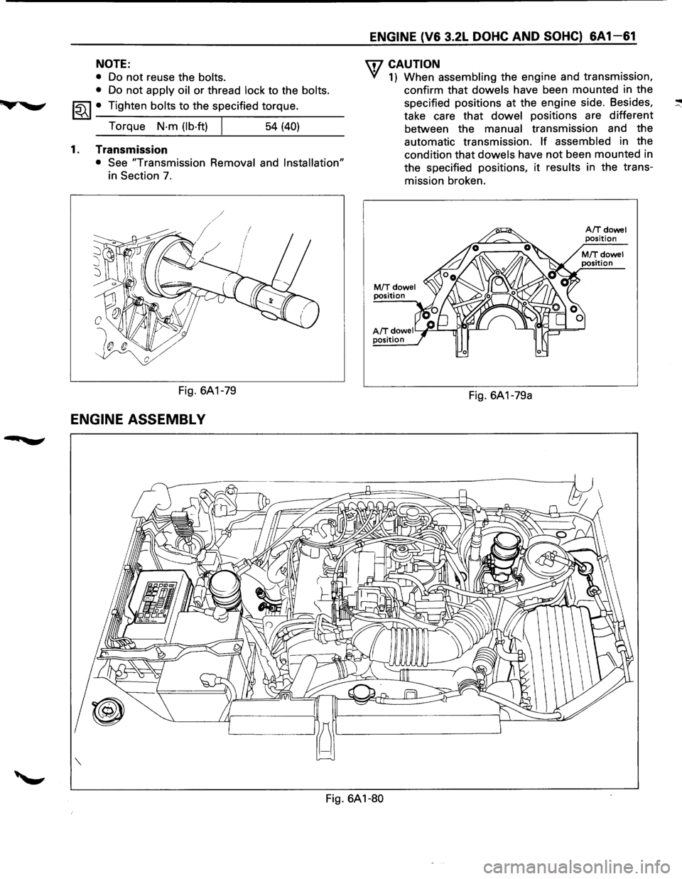
U7 CAUTION
VI 1) When assembling the engine and transmission,
confirm that
dowels have been mounted in the
specified positions at the engine side. Besides,
take care that
dowel positions are different
between the
manual transmission and the
automatic transmission.
If assembled in the
condition that
dowels have not been mounted in
the specified positions,
it results in the trans
mission broken.
M/Tdowel position
AIT dowe I Y~---...rr"lr-'1--' position
Fig. 6A1-79a
A/Tdowel position
Fig. 6A1-80
Page 620 of 1928
'.n
6A1-62 ENGINE (V6 3.2L DOHC AND SOHC)
E) REMOVAL
Preparation: • Disconnect battery ground cable.
• Remove engine hood.
In order to return the hood to the
original position exactly, make
alignment on the hood and hinges
before
removal.
•
Drain radiator coolant.
1. Accelerator cable
• Disconnect from throttle valve and common
chamber.
2. Ventilation hose
3.
Air hose
4. Air cleaner assembly
5. Canister vacuum hose
6. Vacuum booster hose
7. Engine harness connectors
• Disconnect three connectors on canister side.
8. Battery ground cables
• Disconnect two black and white connector
clips
from the power steering pump bracket.
9. Ground cables
• Disconnect two terminals connected to the
battery support and the
front right frame.
1 0. Bonding cable connector
• Disconnect connector on the left side dash
panel.
11. Bonding cable terminal
• Disconnect terminal on the back of left bank.
12. Starter harness connector
• Disconnect from starter.
13. Radiator
• Disconnect upper and lower hoses from the
engine.
• Disconnect coolant reserve tank hose from
radiator.
• Disconnect ATF hose from the pipe. (A/T)
• Remove radiator lower hose clip from the hose
bracket.
• Remove radiator lower fan shroud.
• Remove radiator.
14. Power steering pump drive belt
15. Power steering pump
• Remove two bolts on the bracket, and place the
pump along with piping on the body side.
16. Air Conditioning compressor drive belt
17. Air Conditioning compressor
• Remove fixing bolts and shift aside the
compressor
with piping attached.
18. Heater hoses
• Disconnect two hoses from the engine.
19. ATF pipes
• Disconnect two pipes from right side engine
mount.
20. Transmission assembly
• See "Transmission Removal and Installation"
in Section 7.
21. Left side engine mount
• Support the engine.
• Remove two fixing bolts from engine mount on
chassis side.
22. Right side engine mount
• Remove two fixing bolts from engine mount on
chassis side.
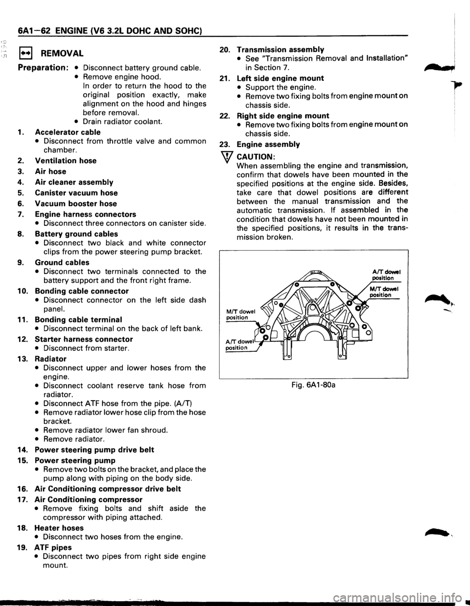
23. Engine assembly
w CAUTION:
When assembling the engine and transmission,
confirm
that dowels have been mounted in the
specified positions at the engine side. Besides,
take care
that dowel positions are different
between the manual transmission and the
automatic transmission.
If assembled in the
condition that dowels have not been mounted in
the specified positions,
it results in the trans
mission broken.
M/Tdowel position
AIT doweiY~--r..ri~-' position
Fig. 6A1-80a
n t b,
•