ISUZU TROOPER 1995 Workshop Manual
TROOPER 1995
ISUZU
ISUZU
https://www.carmanualsonline.info/img/61/57183/w960_57183-0.png
ISUZU TROOPER 1995 Workshop Manual
Page 621 of 1928
·-------------------------------------
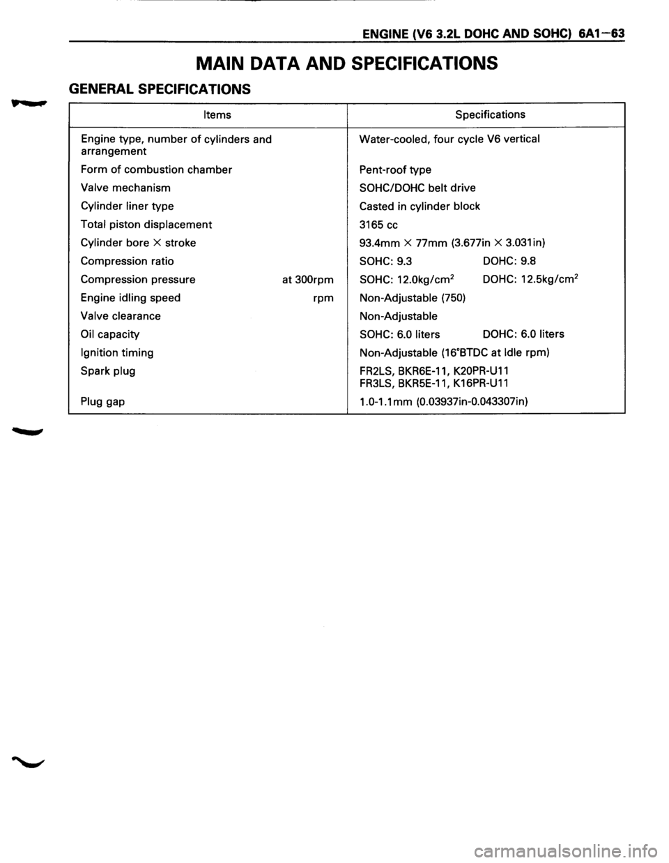
ENGINE (V6 3.2L DOHC AND SOHC) 6A1-63
MAIN DATA AND SPECIFICATIONS
GENERAL SPECIFICATIONS
Items S pacifications
Engine type,
number of cylinders and Water-cooled, four cycle V6 vertical
arrangement
Form
of combustion chamber
Pent-roof type
Valve mechanism SOHC/DOHC belt drive
Cylinder liner type
Casted in cylinder block
Total
piston displacement
3165 cc
Cylinder bore X stroke 93.4mm X 77mm (3.677in X 3.031 in)
Compression ratio
SOHC: 9.3 DOHC: 9.8
Compression pressure
at
300rpm SOHC: 12.0kg/cm2 DOHC: 12.5kg/cm2
Engine idling speed rpm Non-Adjustable (750)
Valve clearance Non-Adjustable
Oil capacity SOHC: 6.0 liters DOHC:
6.0 liters
Ignition
timing Non-Adjustable (16.BTDC at Idle rpm)
Spark
plug FR2LS, BKR6E-11, K20PR-U11
FR3LS, BKR5E-11 I K16PR-U11
Plug gap 1.0-1.1 mm (0.03937in-0.043307in)
Page 622 of 1928
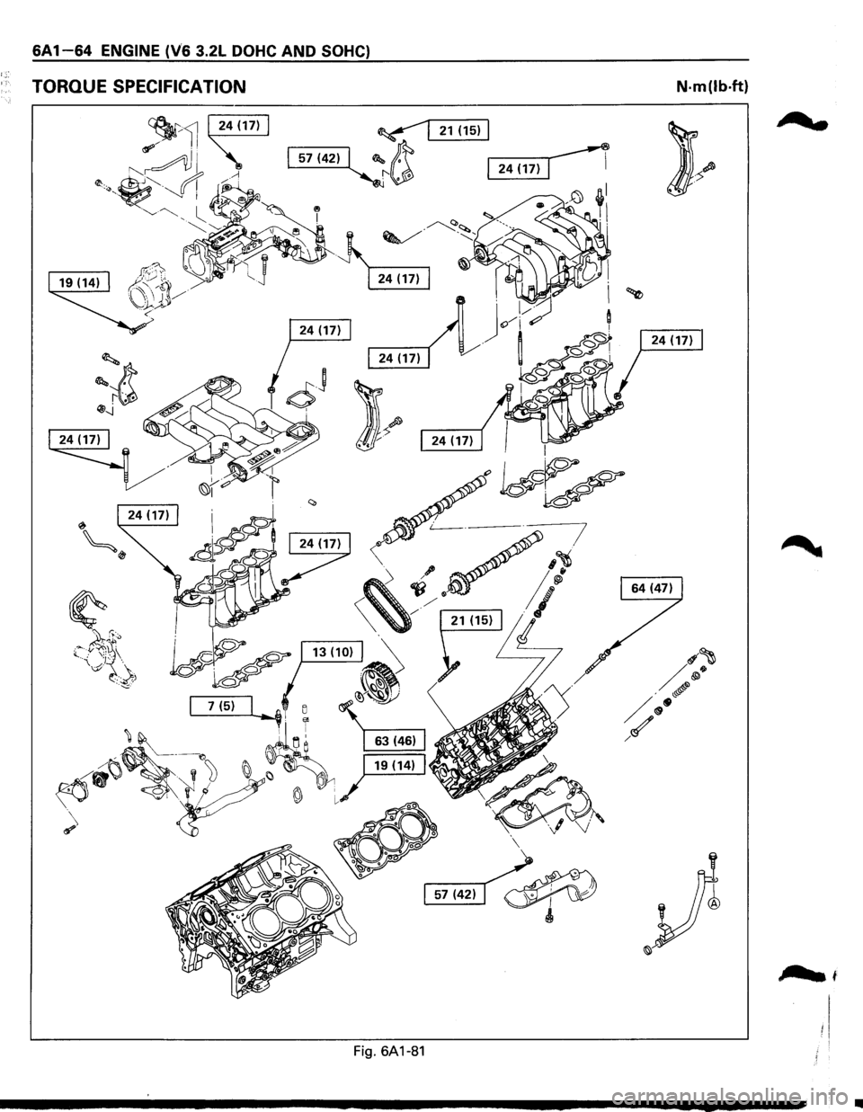
6A 1-64 ENGINE (V6 3.2L DOHC AND SOHC)
TORQUE SPECIFICATION N·m(lb·ft)
;?wt
Fig. 6A1-81
..
Page 623 of 1928
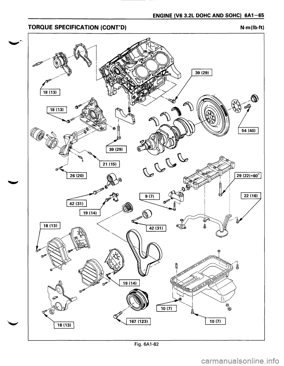
ENGINE (V6 3.2L DOHC AND SOHC) 6A1-65
TORQUE SPECIFICATION (CONT'D) N·m(lb·ft)
Fig. 6A1-82
Page 624 of 1928
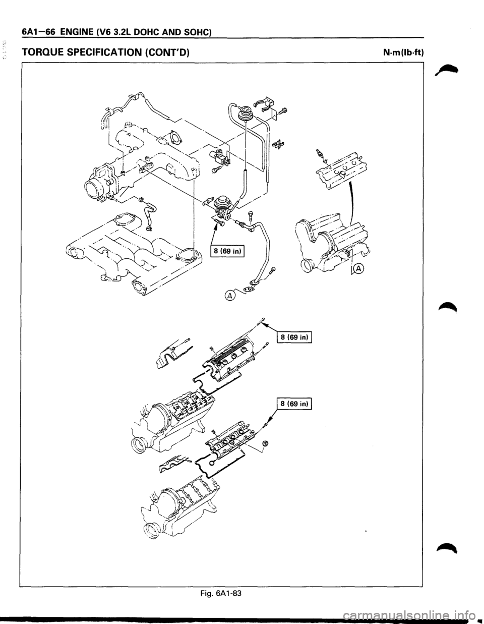
6A1-66 ENGINE (V6 3.2L DOHC AND SOHC)
TORQUE SPECIFICATION (CONT'D) N·m(lb·ft)
~. ~ 8(69in)
!1/" ';>~
~
··~· ~ -~\1W~ .· /
··~v·/~~~ (( .. ' ( /./ /'' ' . /~
·.··~ ··~rY;>""
.. ~
Fig. 6A1-83
..
Page 625 of 1928
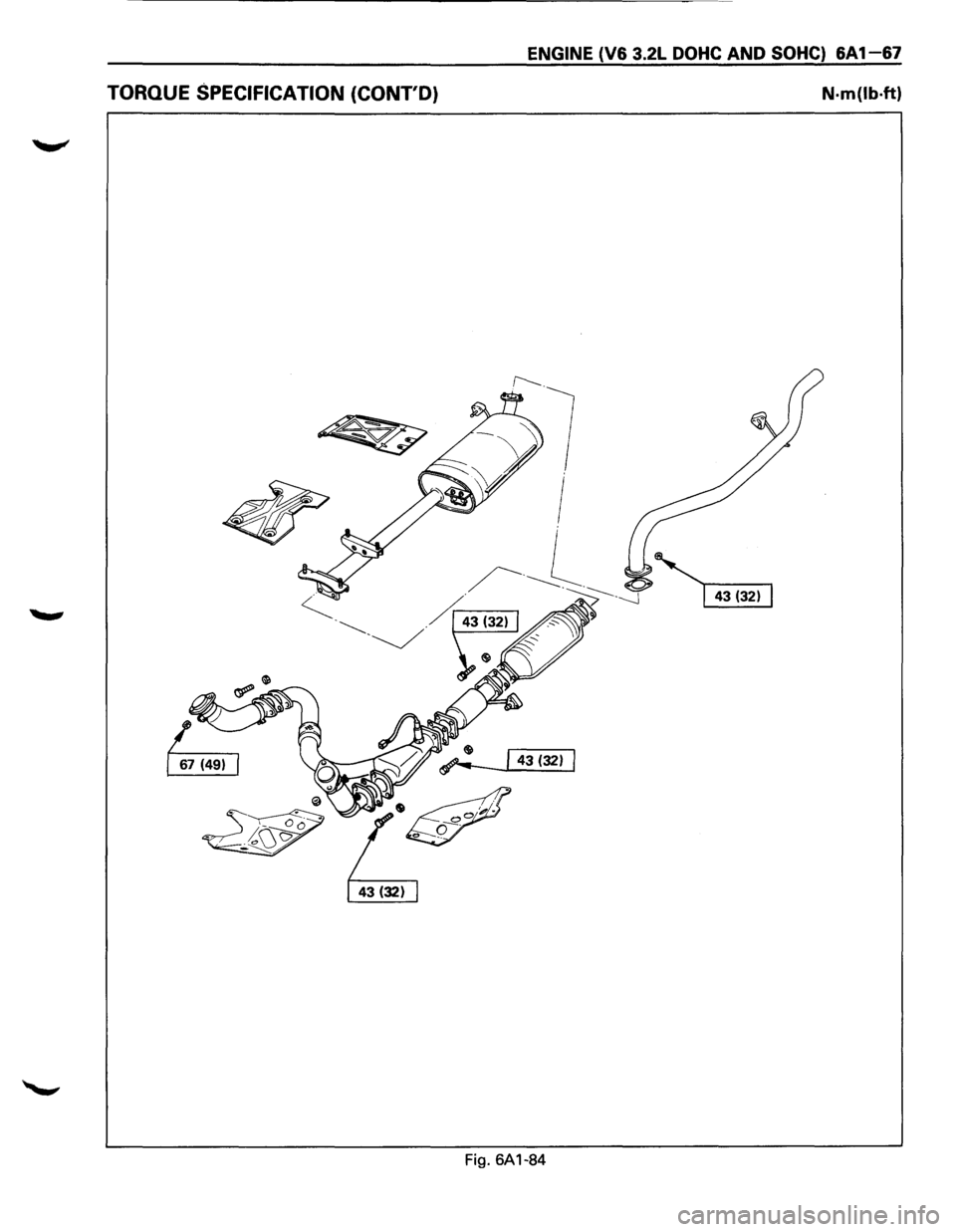
ENGINE (V6 3.2L DOHC AND SOHC) 6A1-67
TORQUE SPECIFICATION (CONT'D) N·m(lb·ft)
Fig. 6A1-84
Page 626 of 1928
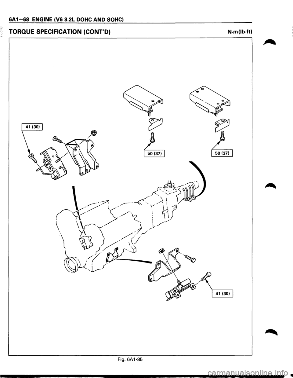
6A 1-68 ENGINE (V6 3.2L DOHC AND SOHC)
·~:; 1 TORQUE SPECIFICATION (CONT'D) N·m(lb·ft)
Fig. 6A1-85
Ill
Page 627 of 1928
ENGINE (V6 3.2L DOHC AND SOHC) 6A1-69
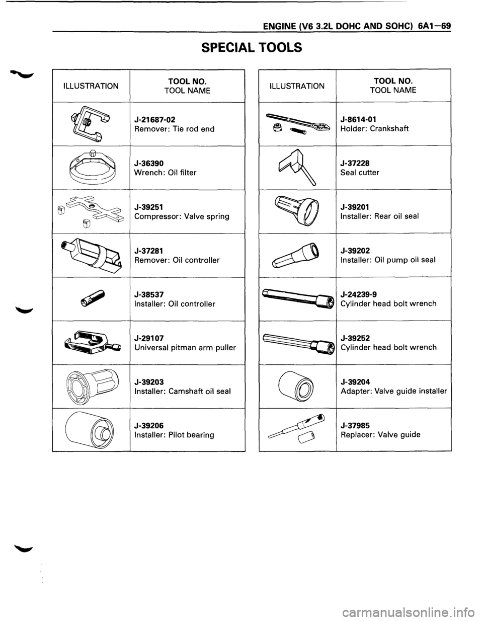
SPECIAL TOOLS
ILLUSTRATION TOOL NO.
TOOL NAME ILLUSTRATION TOOL NO.
TOOL NAME
~
J-21687-02
Remover: Tie rod end ~
J-8614-01
Holder: Crankshaft
0
J-36390
Wrench: Oil filter
~
J-37228
Seal cutter
~~
J-39251
Compressor: Valve spring
~ ~
J-39201
Installer:
Rear oil seal
~
J-37281
Remover:
Oil controller ~
J-39202
Installer: Oil
pump oil seal
~
J-38537
Installer: Oil controller
~
~
J-24239-9
Cylinder head bolt wrench
~
J-29107
Universal pitman arm puller ~
J-39252
Cylinder head bolt wrench
~
J-39203
Installer:
Camshaft oil seal Q co
J-39204
Adapter: Valve guide installer
Qg
J-39206 Installer: Pilot
bearing 4
J-37985
Replacer: Valve guide
Page 628 of 1928
Page 629 of 1928
ENGINE COOLING 68-1
SECTION 68
ENGINE COOLING
CONTENTS
General Description . . . . . . . . . . . . . . . . . . . . . . . . . . 68-1 Radiator . . . . . . . . . . . . . . . . . . . . . . . . . . . . . . . . . . . . . . 68-7
Diagnosis........................................ 68-3 Drive Belt Adjustment . . . . . . . . . . . . . . . . . . . . 68-1 0
On-Vehicle Service............................ 68-4 Main Data and Specifications .............. 68-12
Water Pump . . . . . . . . . . . . . . . . . . . . . . . . . . . . . . . . 68-4
Thermostat . . . . . . . . . . . . . . . . . . . . . . . . . . . . . . . . . . 68-6
Torque Specifications .................... 68-12
Special Tools ................................... 68-13
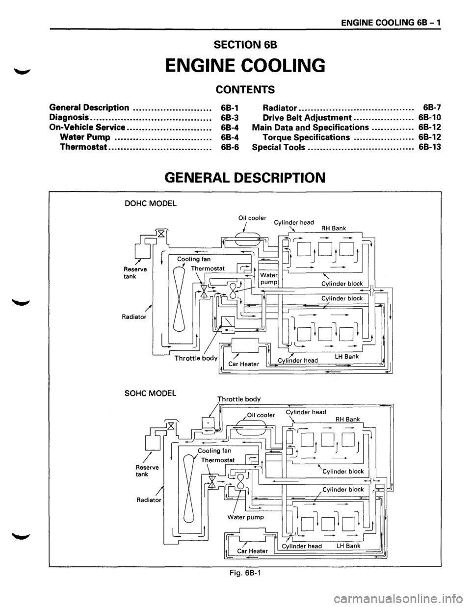
GENERAL DESCRIPTION
DOHC MODEL
Reserve tank
/ Radiator
SOHC MODEL
Radiator
Oil cooler
Throttle body
Fig. 68-1
Cylinder head
"'
RH Bank
' Cylinder bloc~~
Cylinder block
LH Bank
Cylinder block
~
lololol ~ I
~L: - -~,t
Cylinder head LH Bank d
d
Page 630 of 1928
68 - 2 ENGINE COOLING
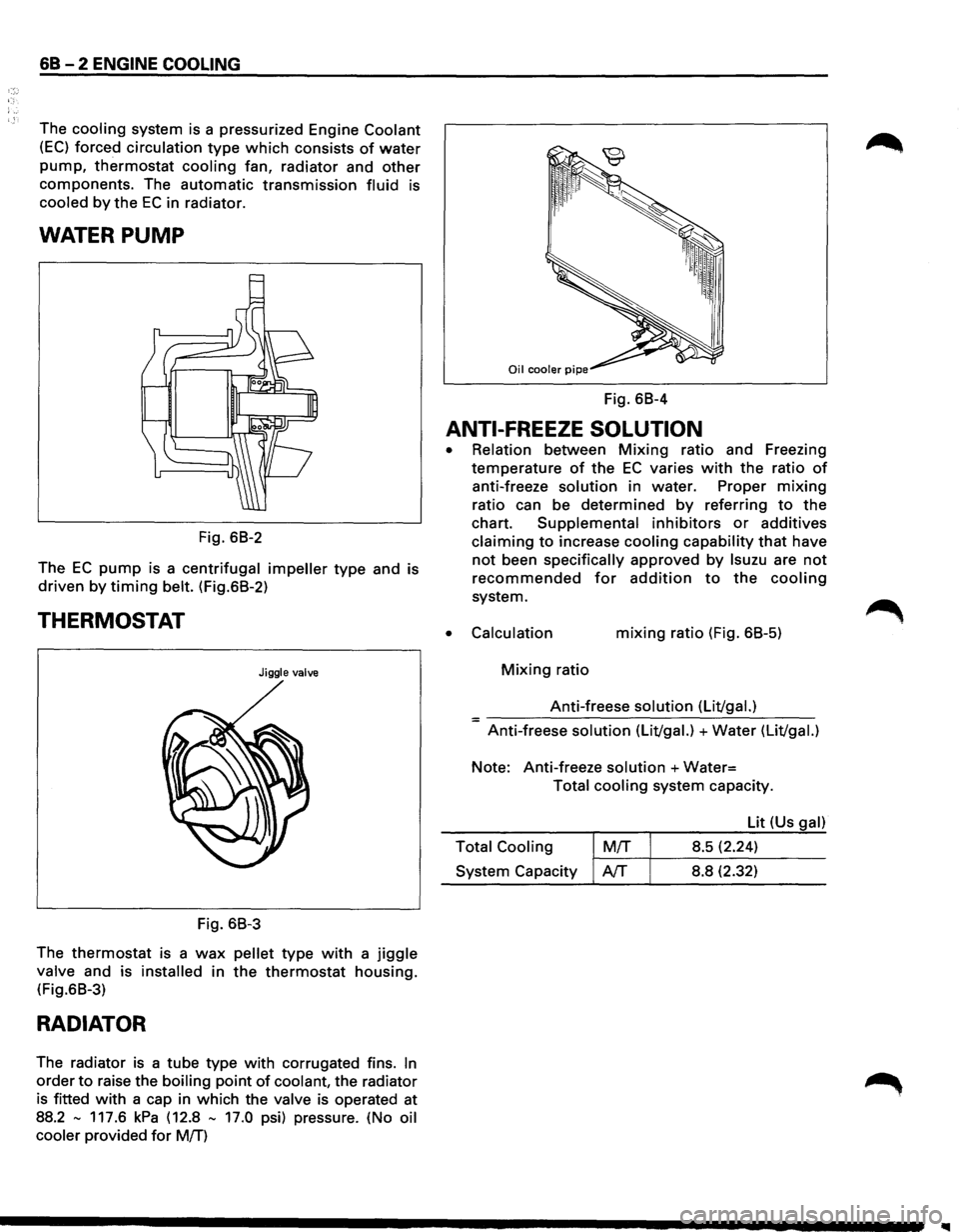
The cooling system is a pressurized Engine Coolant
(EC) forced circulation type which consists of water
pump, thermostat cooling fan, radiator and other
components. The automatic transmission fluid is
cooled by the EC in radiator.
WATER PUMP
Fig. 68-2
The
EC pump is a centrifugal impeller type and is
driven by timing belt. (Fig.68-2)
THERMOSTAT
Jiggle valve
Fig. 68-3
The
thermostat is a wax pellet type with a jiggle
valve and is installed in the thermostat housing.
(Fig.68-3)
RADIATOR
The radiator is a tube type with corrugated fins. In
order to raise the boiling point of coolant, the radiator
is fitted
with a cap in which the valve is operated at
88.2
-117.6 kPa (12.8 - 17.0 psi) pressure. (No oil
cooler
provided for M!f)
Fig. 68-4
ANTI-FREEZE SOLUTION
•
•
Relation between Mixing ratio and Freezing
temperature
of the EC varies with the ratio of
anti-freeze solution in water. Proper mixing
ratio can be determined by referring to the
chart. Supplemental inhibitors or additives
claiming to increase cooling capability that have
not been specifically approved by lsuzu are not
recommended for addition to the cooling
system.
Calculation mixing ratio (Fig. 68-5)
Mixing ratio
Anti-freese
solution (Lit/gal.) =-----------------Anti-freese solution (Lit/gal.) +Water (Lit/gal.)
Note: Anti-freeze solution +Water=
Total cooling system capacity.
Lit (Us
gal)
Total Cooling
M!f 8.5 (2.24) ~-~~--------System Capacity AfT 8.8 (2.32)