ISUZU TROOPER 1995 Workshop Manual
Manufacturer: ISUZU, Model Year: 1995, Model line: TROOPER, Model: ISUZU TROOPER 1995Pages: 1928
Page 681 of 1928
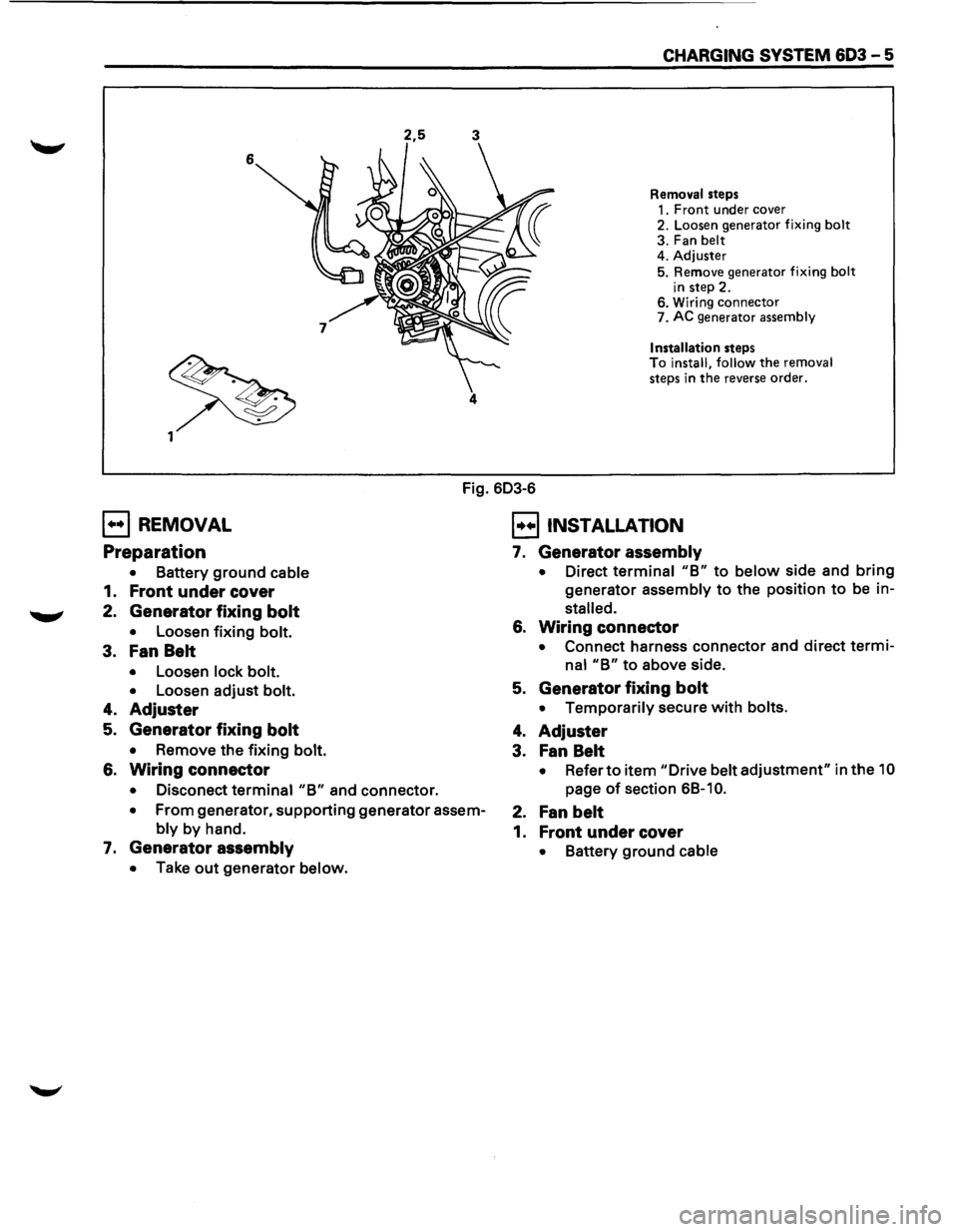
2,5 3
6 4
CHARGING SYSTEM 603 - 5
Removal steps
1. Front under cover
2. Loosen generator fixing bolt
3. Fan belt
4. Adjuster
5. Remove generator fixing bolt
in step 2. 6. Wiring connector
7. AC generator assembly
Installation steps To install, follow the removal
steps in
the reverse order.
Fig. 603-6
E] REMOVAL
Preparation
• Battery ground cable
1. Front under cover
2. Generator fixing bolt
• Loosen fixing bolt.
3. Fan Belt
• Loosen lock bolt.
•
Loosen adjust bolt.
4. Adjuster
5. Generator fixing bolt
• Remove the fixing bolt.
6. Wiring connector
• Disconect terminal "B" and connector.
• From generator, supporting generator assem
bly by hand.
7. Generator assembly
• Take out generator below.
EJ INSTALLATION
7. Generator assembly
• Direct terminal "B" to below side and bring
generator assembly to the position to be in
stalled.
6. Wiring connector
• Connect harness connector and direct termi
nal "B" to above side.
5. Generator fixing bolt
• Temporarily secure with bolts.
4. Adjuster
3. Fan Belt
• Refer to item "Drive belt adjustment" in the 10
page of section 6B-1 0.
2. Fan belt
1. Front under cover
• Battery ground cable
Page 682 of 1928
603-6 CHARGING SYSTEM
UNIT REPAIR
8
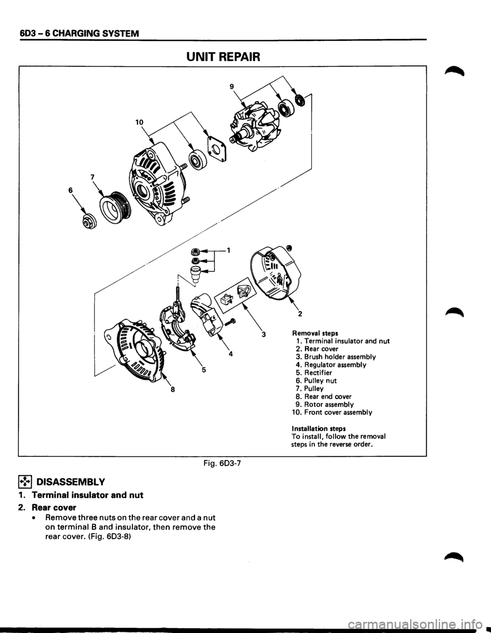
Fig. 603-7
l•!•l DISASSEMBLY
1. Terminal insulator and nut
2. Rear cover
• Remove three nuts on the rear cover and a nut
on terminal 8 and insulator, then remove the
rear cover. (Fig. 603-8)
3 Removal steps
1. Terminal insulator and nut 2. Rear cover
3. Brush holder assembly
4. Regulator assembly
5. Rectifier
6.
Pulley nut
7. Pulley 8. Rear end cover
9. Rotor assembly
10. Front cover assembly
Installation
steps
To install, follow the removal steps in the reverse order.
•
Page 683 of 1928
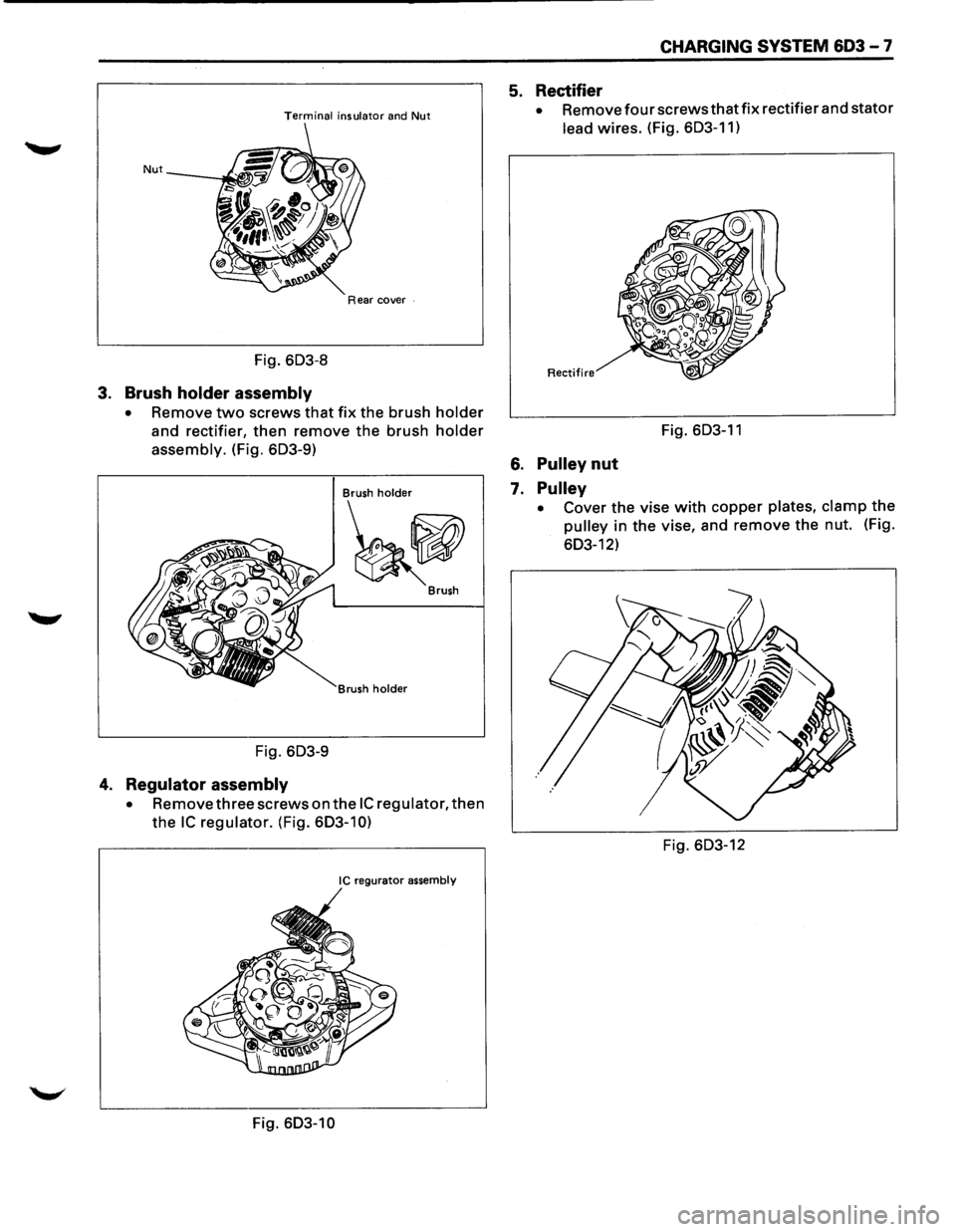
Terminal insulator and Nut
Nut
Rear cover .
Fig. 603-8
3. Brush holder assembly
• Remove two screws that fix the brush holder
and rectifier, then remove the brush holder
assembly. (Fig. 603-9)
Brush holder
~ Brush
rush
holder
Fig. 603-9
4. Regulator assembly
• Remove three screws on the IC regulator, then
the IC regulator. (Fig. 603-10)
IC regurator assembly
Fig. 603-10
CHARGING SYSTEM 603 - 7
5. Rectifier
• Removefourscrewsthatfix rectifier and stator
lead wires. (Fig. 603-11)
Rectifire
Fig. 603-11
6. Pulley nut
7. Pulley
• Cover the vise with copper plates, clamp the
pulley in the vise, and remove the nut. (Fig.
603-12)
Fig. 603-12
Page 684 of 1928
603 - 8 CHARGING SYSTEM
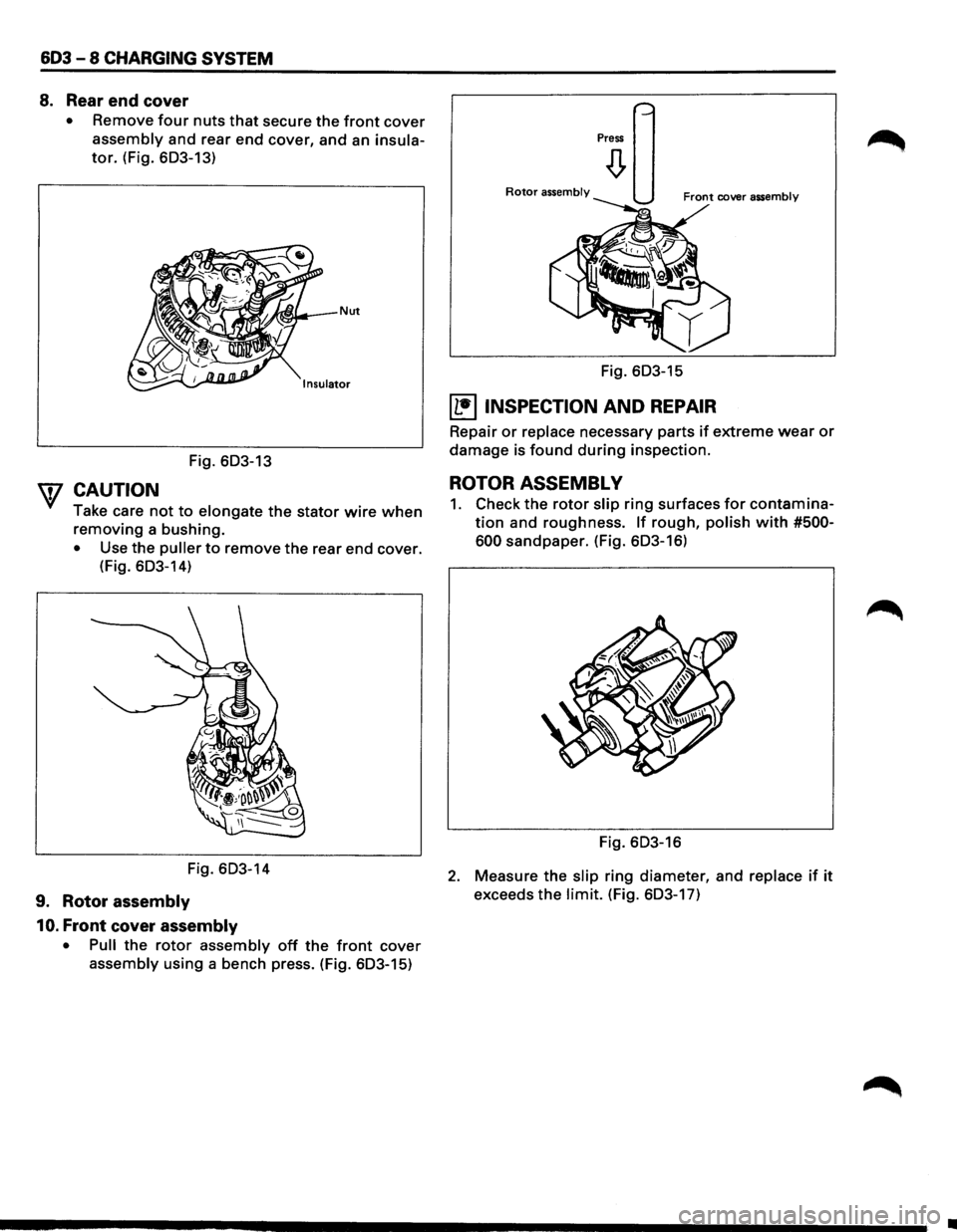
8. Rear end cover
• Remove four nuts that secure the front cover
assembly and rear end cover, and an insula
tor. (Fig. 603-13)
Fig. 603-13
W CAUTION
Take care not to elongate the stator wire when
removing a bushing.
• Use the puller to remove the rear end cover.
(Fig.
603-14)
Fig. 603-14
9. Rotor assembly
10.
Front cover assembly
• Pull the rotor assembly off the front cover
assembly using a bench press. (Fig. 603-15)
Press
Rotor assembly
Fig. 603-15
~ INSPECTION AND REPAIR
Repair or replace necessary parts if extreme wear or
damage is found during inspection.
ROTOR ASSEMBLY
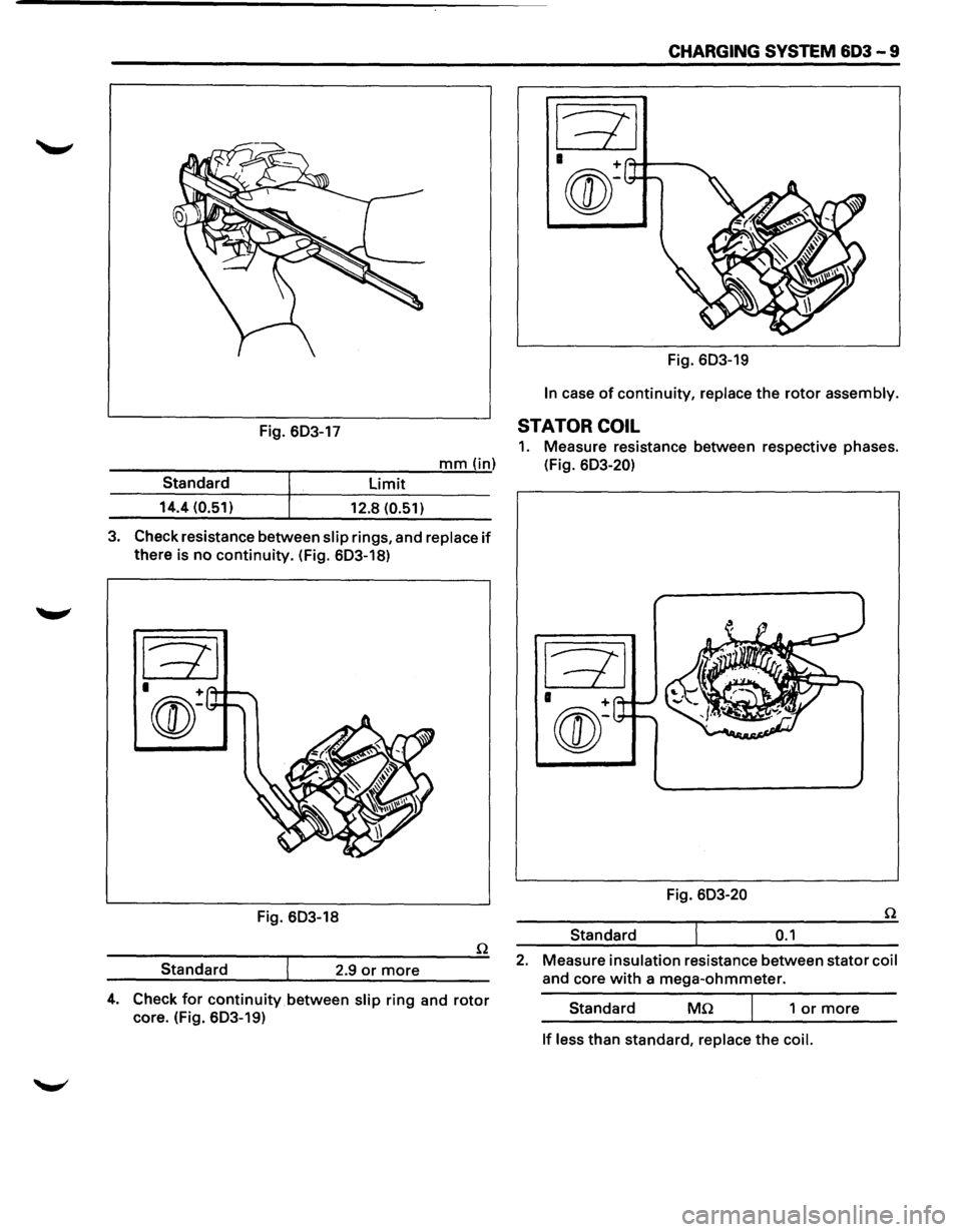
1. Check the rotor slip ring surfaces for contamina
tion and roughness. If rough, polish with #500-
600
sandpaper. (Fig. 603-16)
Fig. 603-16
2. Measure the slip ring diameter, and replace if it
exceeds the limit. (Fig. 603-17)
•
Page 685 of 1928
CHARGING SYSTEM 603 - 9
Fig. 603-19
In case of continuity, replace the rotor assembly.
Fig. 603-17 STATOR COIL
1. Measure resistance between respective phases.
---------r-----:-:--:---'m;.;..;.;...;.m""'"(.....,..in) (Fig. 603-20)
limit Standard
14.4 (0.51)
12.8 (0.51)
3. Check resistance between slip rings, and replace if
there is no continuity. (Fig. 603-18)
Fig. 603-18
Standard 2.9
or more
4. Check for continuity between slip ring and rotor
core. (Fig. 603-19) Fig.
603-20
Standard
0.1
2. Measure insulation resistance between stator coil
and core with a mega-ohmmeter.
Standard
Mn 1 or more
If less than standard, replace the coil.
Page 686 of 1928
603 -10 CHARGING SYSTEM
BRUSH
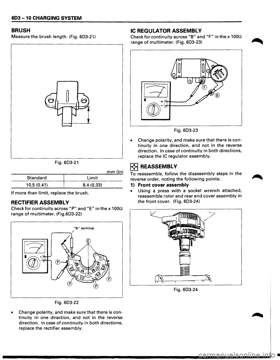
Measure the brush length. (Fig. 603-21)
Fig. 603-21
mm (in)
Standard
Limit
10.5 (0.41) 8.4 (0.33)
If more than limit, replace the brush.
RECTIFIER ASSEMBL V
Check for continuity across "P" and "E" in the x 100Q
range of multimeter. (Fig.603-22)
"B" terminal r---....... /
®
Fig. 603-22
• Change polarity, and make sure that there is con
tinuity in one direction, and not in the reverse
direction.
In case of continuity in both directions,
replace the rectifier assembly.
IC REGULATOR ASSEMBL V
Check for continuity across "B" and "F" in the x 100Q
range of multimeter. (Fig. 603-23)
Fig. 603-23
• Change polarity, and make sure that there is con
tinuity in one direction, and not in the reverse
direction.
In case of continuity in both directions,
replace
the IC regulator assembly.
l•!•l REASSEMBLY
To reassemble, follow the disassembly steps in the
reverse order,
noting the following points:
1) Front cover assembly
• Using a press with a socket wrench attached,
reassemble
rotor and rear end cover assembly in
the
front cover. (Fig. 603-24)
Fig. 603-24
•
Page 687 of 1928
-
2) Pulley nut
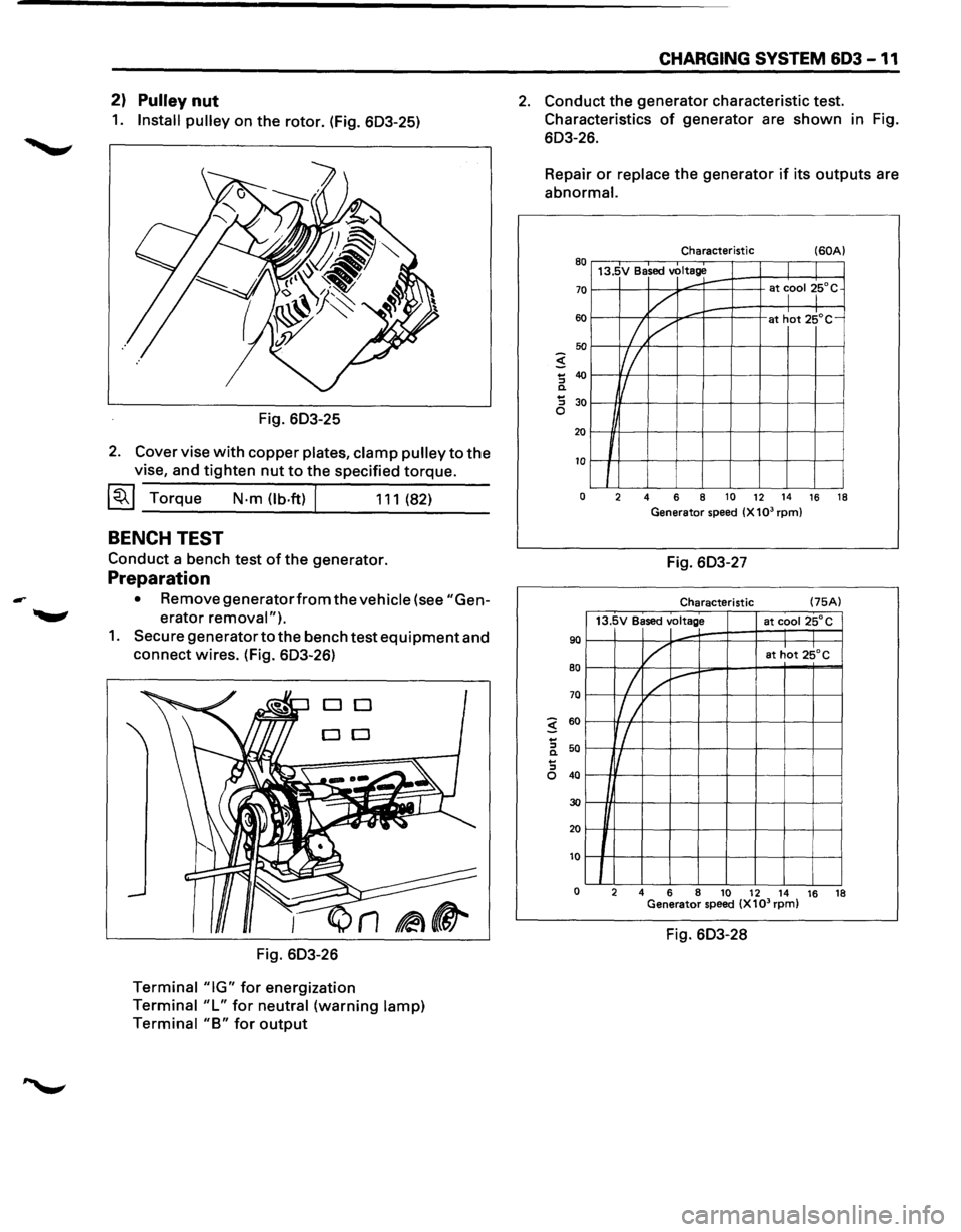
1. Install pulley on the rotor. (Fig. 603-25)
Fig. 603-25
2. Cover vise with copper plates, clamp pulley to the
vise, and tighten nut to the specified torque.
~~~Torque N-m(lb.ft) 111(82)
BENCH TEST
Conduct a bench test of the generator.
Preparation
• Remove generatorfrom the vehicle (see "Gen
erator removal").
1. Secure generator to the bench test equipment and
connect wires. (Fig. 603-26)
DO
DO
Fig. 603-26
Terminal "IG" for energization
Terminal "L" for neutral (warning lamp)
Terminal
"B" for output
CHARGING SYSTEM 603 -11
2. Conduct the generator characteristic test.
Characteristics
of generator are shown in Fig.
603-26.
Repair
or replace the generator if its outputs are
abnormal.
Characteristic (60A) 80 13.5V Based voltage
70
60
50
5 ... 40 "' c. ... 30 "'
......... r-at lool ~5°C
v ,........
/, /
at hot 25°C-
Iff_
f/
0
20
10
J 0 2 4 6 8 10 12 14 16 18
Generator speed (X 103 rpm)
Fig. 603-27
Characteristic (75A)
13.5V Based
voltage at cooi25°C
90
80
70
5 60
...
"' 50 c. ...
v at hot 25°C
I / ~
l/ /
r/
I
"' 0 40
30
20
10
0 2
4 6
8
10 12 14 16
18
Generator speed (X103 rpm)
Fig. 603-28
Page 688 of 1928
603 -12 CHARGING SYSTEM
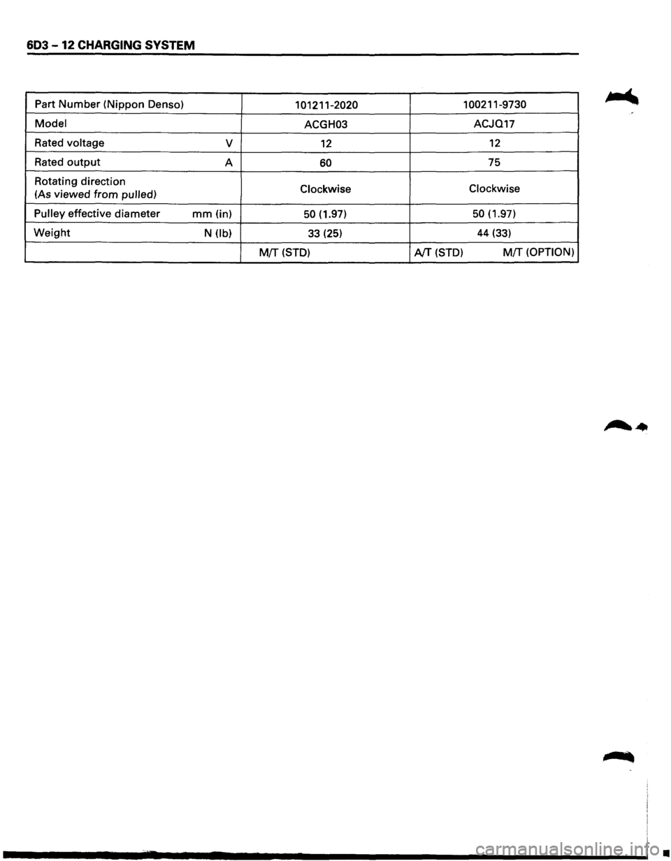
Part Number (Nippon Denso) 101211-2020 1 00211-9730
Model ACGH03 ACJQ17
Rated
voltage v 12 12
Rated output A 60 75
Rotating direction
Clockwise Clockwise (As
viewed from pulled)
Pulley
effective diameter mm (in) 50 (1.97) 50 (1.97)
Weight N (lb) 33 (25) 44 (33)
M{f (STD) AfT (STD) M!T (OPTION)
•
Page 689 of 1928
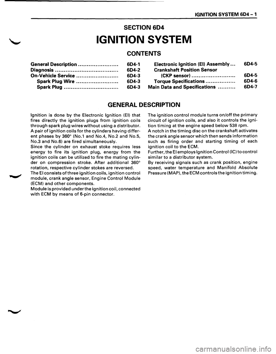
IGNITION SYSTEM 6D4 - 1
SECTION 604
IGNITION SYSTEM
CONTENTS
General Description ...................... .
Diagnosis
................................... .
On-Vehicle Service ....................... .
Spark Plug Wire ....................... .
Spark Plug .............................. . 6D4-1
6D4-2 6D4-3
6D4-3
6D4-3
Electronic Ignition (EI) Assembly ...
Crankshaft Position Sensor
(CKP sensor) ........................ .
Torque Specifications
................ .
Main Data and Specifications
......... . 6D4-5
6D4-5
6D4-6
6D4-7
GENERAL DESCRIPTION
Ignition is done by the Electronic Ignition (EI) that
fires directly the ignition plugs from ignition coils
through spark plug wires without using a distributor.
A pair of ignition coils for the cylinders having differ
ent phases by 360° (No.1 and No.4, No.2 and No.5,
No.3 and No.6) are
fired simultaneously.
Since the cylinder on exhaust stoke requires less
energy to fire its ignition plug, energy from the
ignition coils can be utilized to fire the mating cylin
der on compression stroke. After additional 360°
rotation, respective cylinder stokes are reversed.
TheEl consists of three ignition coils, ignition control
module, crank angle sensor, Engine Control Module
(ECM) and other components.
Module is provided under the ignition coil, connected
with ECM by means of 6-pin connector. The
ignition control module turns on/off the primary
circuit of ignition coils, and also it controls the igni
tion timing at the engine
speed below 538 rpm.
A notch in
the timing disc on the crankshaft activates
the crank angle sensor which then sends information
such as firing order and starting timing of each
ignition coil to the ECM.
Further, the El employs Ignition Control (I C) to control
similar to a distributor system.
By receiving
signals such as crank position, engine
speed, water temperature and Manifold Absolute
Pressure (MAP), the ECM controls the ignition timing.
Page 690 of 1928
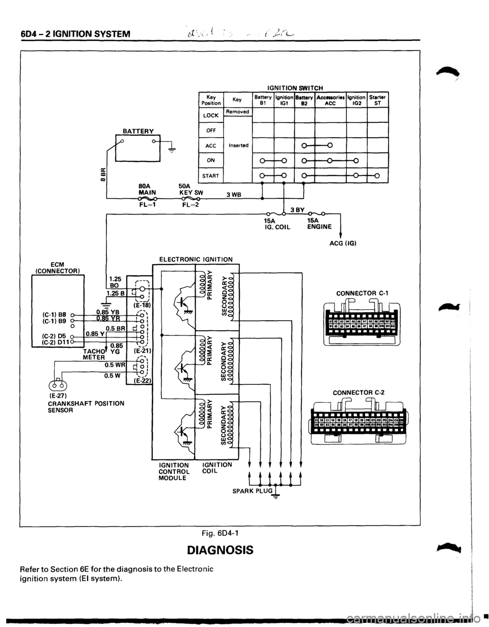
604-2 IGNITION SYSTEM
IGNITION SWITCH
Key
Key Battery
Ignition Battery Acc111ories Ignition
Starter Position 81 IG1 82 ACC IG2 ST
LOCK Removed
BATTERY OFF
/'1 ~ o-
~ Inserted ...... {) ACC ..., -
ON ...... ..... ...... ...... ...... ~ -.....
a: ...... -lXI START Q II) '-' '-' ...., ,_,
BOA 50 A
I 1 MAIN K~YSW 3WB
FL-1 FL-2 3BY -15A 15A IG.COIL ENGINE
ACG (IG)
ELECTRONIC
IGNITION ECM (CONNECTOR) > 1.25 r--""
~~ ~~ BO o""' I
~
1.25 B rrvl -~~ ' f"--~ CONNECTOR C-1
_l_ .... __ .J ~~ c1 mp Shr (E-18)
(C-1) B8 0.85 VB ,, ... , ~~ R!'i YR I I Cl.lo
I !ita lui (C-1) 89 I 0 0.5 BR d 0: IBIBIIIINIBI111Io
(C-2) 05 0.85Y "'I I I > ---(C-2) 011 I
I
)+ 0.85 '-'I a:
~~ ,_, <( TACHO YG (E-21)
~
;;!] METER ,:. .... , a: ~~ 0.5WR q 0! 0... ~~
0.5W I ~$ ... _, ~0 c ( (E-22)
(E-27) CONNECTOR C-2
CRANKSHAFT POSITION .::::> rL
r;::::l enD. .-SENSOR I~ ~~
~ ~ ~~ rt~·· IC4 IT>TiiTiil
f §~
~g l CIJ 0::
·~'l
IGNITION IGNITION CONTROL
COIL MODULE tii1it SPARK PLU
DIAGNOSIS
Refer to Section 6E for the diagnosis to the Electronic
ignition system (EI system).
•