ISUZU TROOPER 1995 Workshop Manual
Manufacturer: ISUZU, Model Year: 1995, Model line: TROOPER, Model: ISUZU TROOPER 1995Pages: 1928
Page 671 of 1928
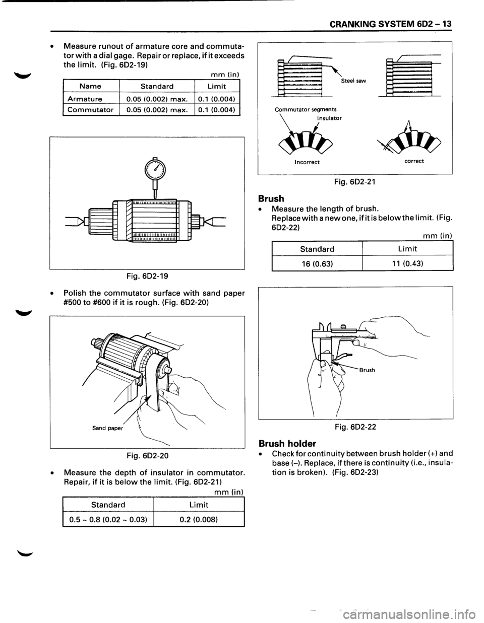
• Measure runout of armature core and commuta
tor with a dial gage. Repair or replace, if it exceeds
the limit. (Fig. 602-19)
mm(in)
Name Standard Limit
Armature 0.05 (0.002) max. 0.1 (0.004)
Commutator 0.05 (0.002) max. 0.1 (0.004)
Fig. 602-19
• Polish the commutator surface with sand paper
#500 to #600 if it is rough. (Fig. 602-20)
Sand paper
Fig. 602-20
•
Measure the depth of insulator in commutator.
Repair, if it is below the limit. (Fig. 602-21)
mm(in)
Standard Limit
0.5 -0.8 (0.02 -0.03) 0.2
(0.008)
CRANKING SYSTEM 602-13
r= I .--/
Steel saw
Commutator segments
~"
Incorrect correct
Fig. 602-21
Brush
• Measure the length of brush.
Replace with a new one, if it is belowthe limit. (Fig.
602-22)
mm(in)
Standard Limit
16 (0.63) 11 (0.43)
Fig. 602-22
Brush holder
• Check for continuity between brush holder(+) and
base(-). Replace, ifthere is continuity (i.e., insula
tion is broken). (Fig. 602-23)
Page 672 of 1928
602-14 CRANKING SYSTEM
Fig. 602-23
Magnetic switch
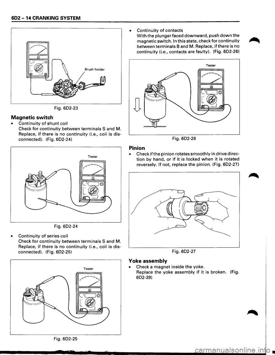
• Continuity of shunt coil
Check for continuity between terminals S and M.
Replace, if there is no continuity (i.e., coil is dis
connected). (Fig. 602-24)
Tester
Fig. 602-24
• Continuity of series coil
Check for continuity between terminals S and M.
Replace, if there is no continuity (i.e., coil is dis
connected). (Fig. 602-25)
Tester
Fig. 602-25
• Continuity of contacts
With the plunger faced downward, push down the
magnetic switch. In this state, check for continuity ~
between terminals Band M. Replace, if there is no
continuity (i.e., contacts are faulty). (Fig. 602-26)
Tester
Fig. 602-26
Pinion
• Check ifthe pinion rotates smoothly in drive direc
tion by hand, or if it is locked when it is rotated
reversely.
If not, replace the pinion. (Fig. 602-27)
Fig. 602-27
Yoke assembly
• Check a magnet inside the yoke.
Replace the yoke assembly if it is broken. (Fig.
602-28)
•
Page 673 of 1928
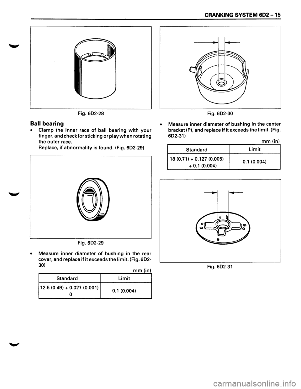
Fig. 602-28
Ball bearing
• Clamp the inner race of ball bearing with your
finger, and check for sticking or play when rotating
the outer race.
Replace, if abnormality is found. (Fig. 602-29)
Fig. 602-29
• Measure inner diameter of bushing in the rear
cover, and
replace if it exceeds the limit. (Fig. 602-
30)
Standard
12.5
(0.49) + 0.027 (0.001)
0
mm (in)
Limit
0.1 (0.004)
•
CRANKING SYSTEM 602-15
Fig. 602-30
Measure inner diameter of bushing in the center
bracket (P), and
replace if it exceeds the limit. (Fig.
602-31)
Standard
18
(0.71) + 0.127 (0.005)
+ 0.1 (0.004)
Fig. 602-31
mm(in)
Limit
0.1 (0.004)
Page 674 of 1928
602 -16 CRANKING SYSTEM
l•!•l REASSEMBL V
To install, follow the removal steps in the reverse
order,
noting the following points:
l<:::~ol Grease application places
• Bushing in rear cover and center bracket
• Gears in reduction gear
• Shift lever operating portion
• Sliding portion of pinion
• Plunger sliding portion of magnetic switch
Reassembling Yoke Assembly
Before reassembly, make sure that no metallic
parts attach to the yoke assembly. Because of
strong magnetic force, hold the yoke assembly
and insert it slowly into the armature.
@J TORQUE
Torque for each part (See page 602-18)
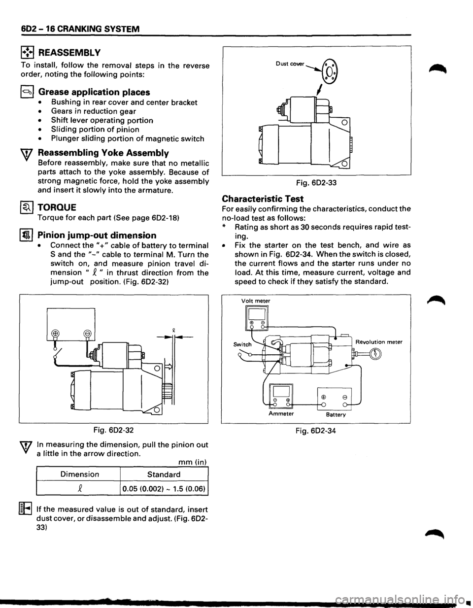
It!!!. I Pinion jump-out dimension
• Connect the"+" cable of battery to terminal
Sand the "-" cable to terminal M. Turn the
switch on, and measure pinion travel di
mension " ~ " in thrust direction from the
jump-out position. (Fig. 602-32)
Fig. 602-32
In measuring the dimension, pull the pinion out
a little in the arrow direction.
mm (in)
Dimension Standard
0.05 (0.002) -1.5 (0.06)
l~Ellf the measured value is out of standard, insert
dust cover, or disassemble and adjust. (Fig. 602-
33)
Dust cover~
_\(J)
,----,1
Fig. 602-33
Characteristic Test
For easily confirming the characteristics, conduct the
no-load test as follows:
* Rating as short as 30 seconds requires rapid test
ing.
• Fix the starter on the test bench, and wire as
shown in Fig. 602-34. When the switch is closed,
the current flows and the starter runs under no
load. At this time, measure current, voltage and
speed
to check if they satisfy the standard.
Volt meter
D I!> e
Fig. 602-34
..
Page 675 of 1928
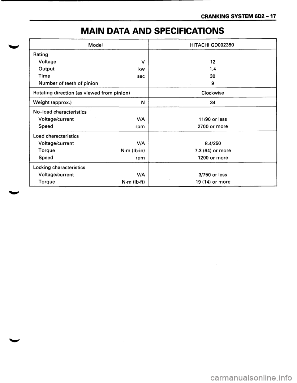
CRANKING SYSTEM 602-17
MAIN DATA AND SPECIFICATIONS
Model HITACHI GD002350
Rating
Voltage v 12
Output kw 1.4
Time sec 30
Number of teeth of pinion
9
Rotating direction (as viewed
from pinion) Clockwise
Weight (approx.)
N 34
No-load characteristics
Voltage/current V/A
11/90 or less
Speed rpm 2700 or more
Load characteristics
Voltage/current V/A
8.4/250
Torque N·m (lb·in) 7.3 (64) or more
Speed rpm 1200 or more
Locking characteristics
Voltage/current V/A
3/750 or less
Torque N·m (lb·ft) 19 (14) or more
Page 676 of 1928
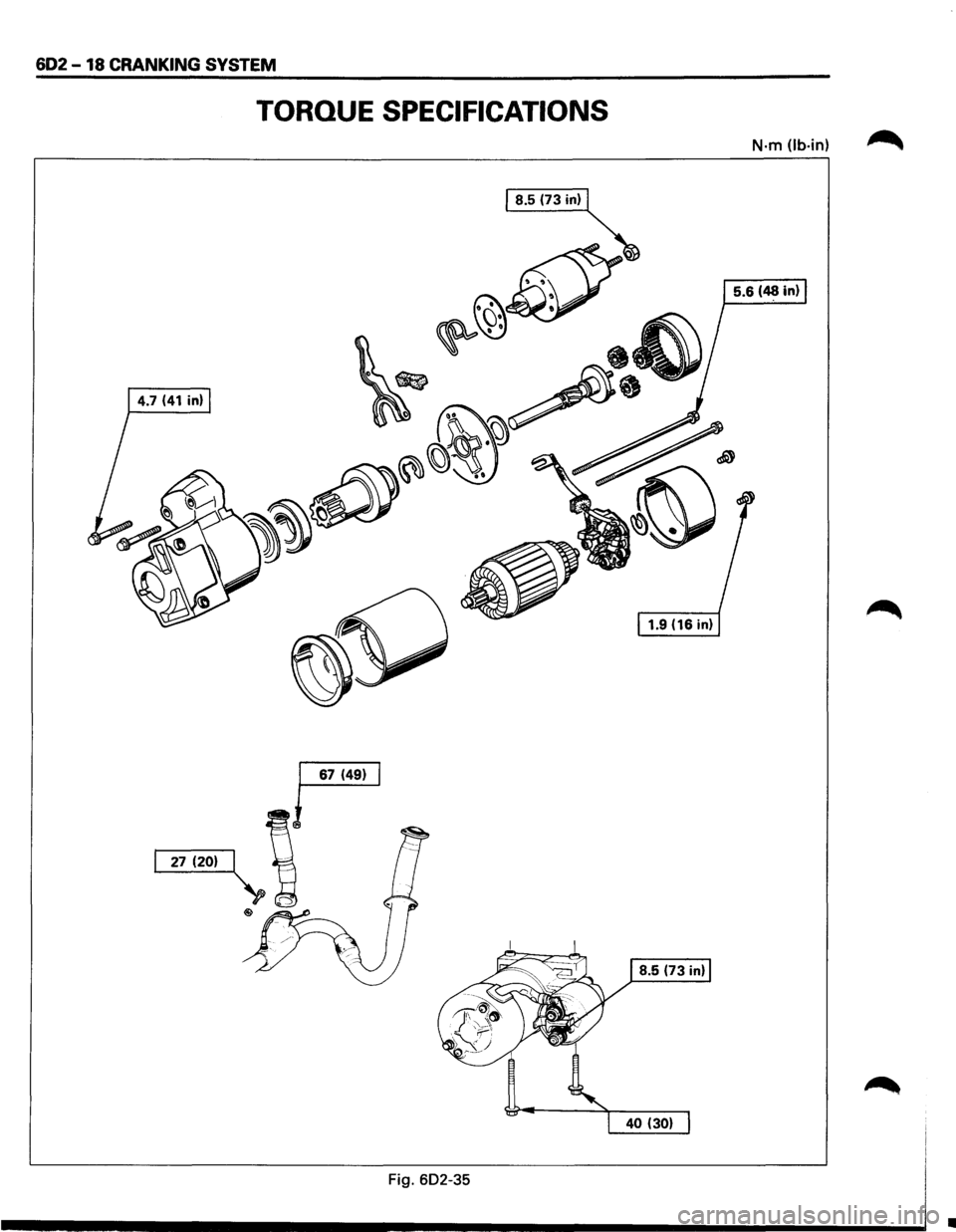
602-18 CRANKING SYSTEM
TORQUE SPECIFICATIONS
N·m (lb·in)
Fig. 602-35
•
Page 677 of 1928
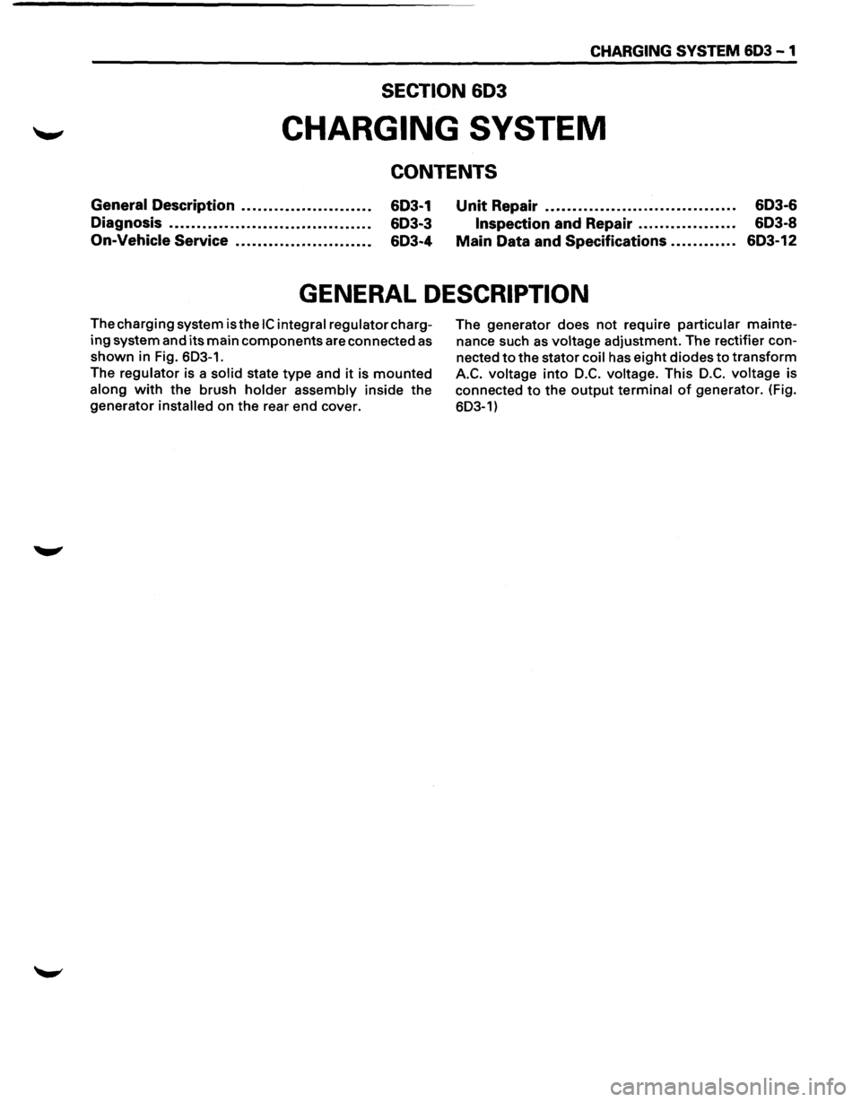
CHARGING SYSTEM 6D3-1
SECTION 603
CHARGING SYSTEM
CONTENTS
General Description ....................... .
Diagnosis
.................................... .
On-Vehicle Service ........................ . 6D3-1
6D3-3
6D3-4 Unit
Repair . . .. .. . . . . . . . . . . . . .. . . . . . . . . . . . . . . . 6D3-6
Inspection and Repair . . . . . . . . . . . . . . . . . . 6D3-8
Main Data and Specifications............ 6D3-12
GENERAL DESCRIPTION
The charging system is the IC integral regulator charg
ing system and its main components are connected as
shown in Fig. 6D3-1.
The regulator is a solid state
type and it is mounted
along with the brush holder assembly inside the
generator installed on the rear end cover. The
generator does not require particular mainte
nance such
as voltage adjustment. The rectifier con
nected
to the stator coil has eight diodes to transform
A.C. voltage into D.C. voltage. This D.C. voltage is
connected
to the output terminal of generator. (Fig.
6D3-1)
Page 678 of 1928
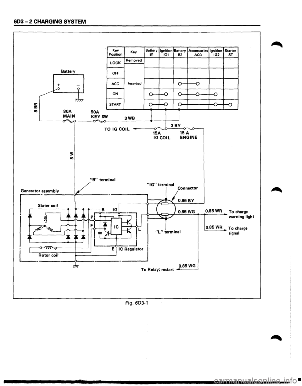
603-2 CHARGING SYSTEM
Battery
+ -...--o ?
,.h,
a: a:l co BOA MAIN . .-. -,., ~
3: co
50 A KEYSW
Key
Position
LOCK
OFF
ACC
ON
START Key
Removed
Inserted
3WB
TO IG COIL
Battery Ignition Battery Accessories Ignition Starter 81 IG1 82 ACC IG2 ST
0 -o
,.... ,....
,.... ,... ,.... ...., ...., ...., ...., ....,
0 ,.... ,.... ,.... 0 ....,
...., ....,
I J
3BY ~ ,.,.
15A 15 A IGCOIL ENGINE
V
"B" termin_a_I _____ _,"IG" terminal
Generator assembly
s_:a_t_er_co __ i_l __ ~~~.-.-~ - Connector
/...-"""\. 0.85BY
B IG
I ~ I ~ A~
-~ ..->--~~ 0.85 WG 0.85 WR To ch arge
' _-: .~:f--<·1'
.~ ~ ~~~~ T ~-r-~ L
. L_ __j
• 1 .... ~ ~ E IC Regulator
L_ Rotor coil ----9---------------'
"L" terminal
warni ng light
0.85WR To ch arge
signal
0.85
WG To Relay, restart
Fig. 603-1
•
Page 679 of 1928
CHARGING SYSTEM 603 -3
DIAGNOSIS
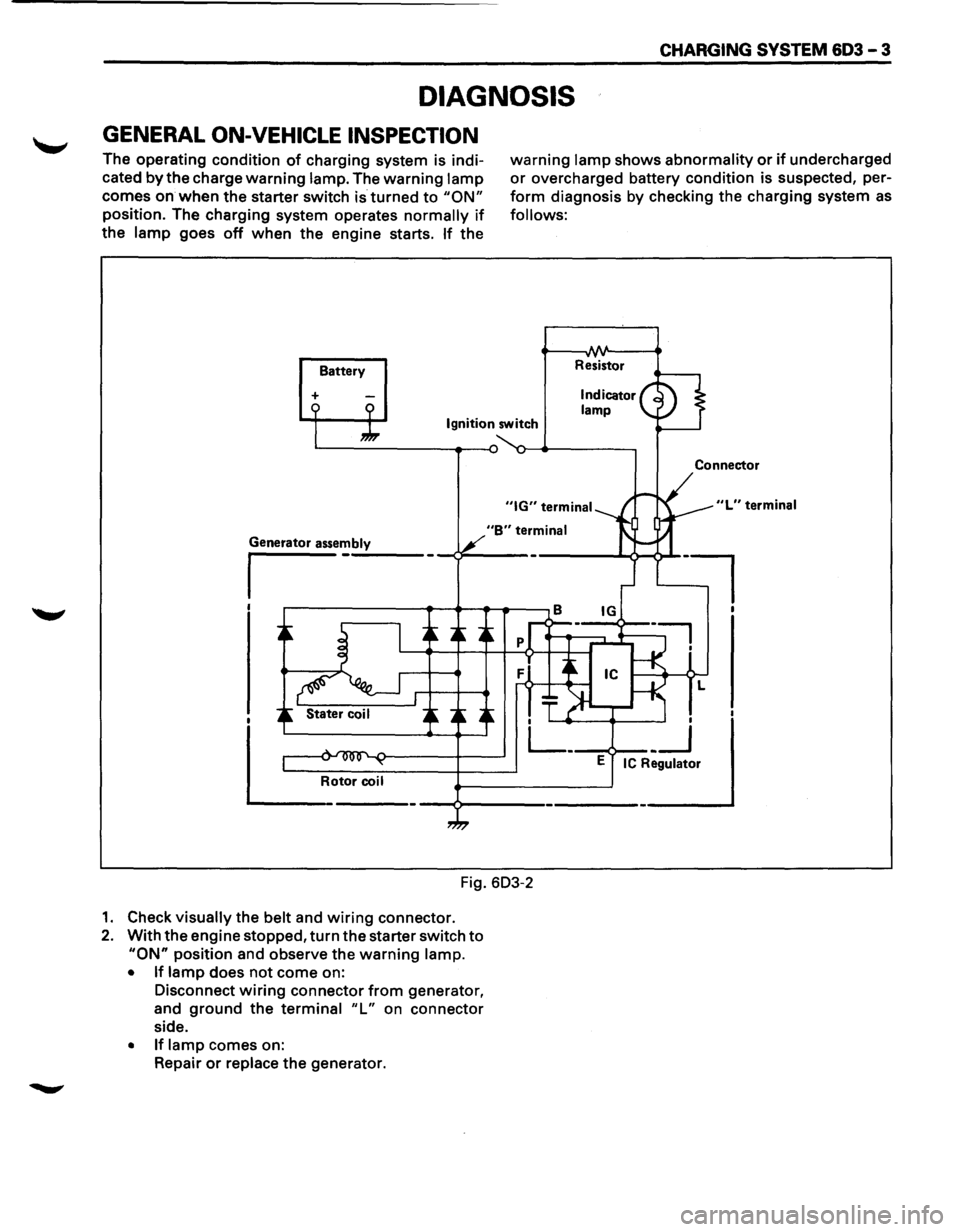
GENERAL ON-VEHICLE INSPECTION
The operating condition of charging system is indi
cated
by the charge warning lamp. The warning lamp
comes on when the starter switch is turned to "ON"
position. The charging system operates normally if
the lamp goes off when the engine starts. If the
Battery
+
warning lamp shows abnormality or if undercharged
or overcharged battery condition is suspected, per
form diagnosis by checking the charging system as
follows:
Resistor
Ignition switch
"B" terminal
Fig. 603-2
1. Check visually the belt and wiring connector.
2. With the engine stopped, turn the starter switch to
"ON" position and observe the warning lamp.
• If lamp does not come on:
Disconnect
wiring connector from generator,
and
ground the terminal "L" on connector
side.
• If lamp comes on:
Repair
or replace the generator.
Connector
"L" terminal
l
Page 680 of 1928
603 - 4 CHARGING SYSTEM
ON-VEHICLE SERVICE
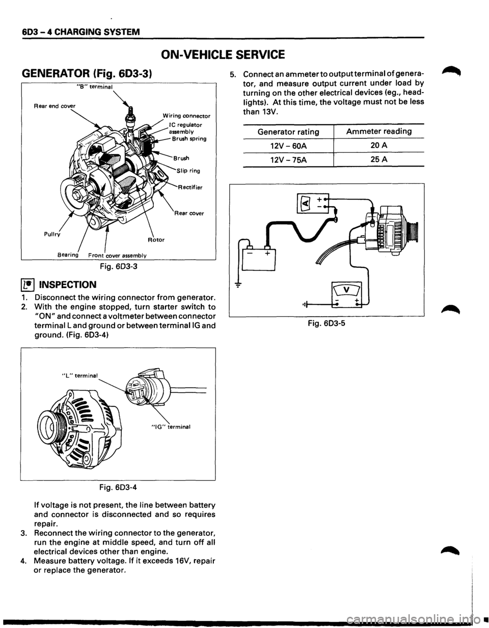
GENERATOR (fig. 603-3}
"B" terminal
Pullry
Fig. 603-3
~ INSPECTION
Wiring connector
I C regulator
assembly
Brush spring
ifier
Rear cover
1. Disconnect the wiring connector from generator.
2. With the engine stopped, turn starter switch to
"ON" and connect a voltmeter between connector
terminal Land ground or between terminaiiG and
ground. (Fig. 603-4)
"IG" terminal
Fig. 603-4
If voltage is not present, the line between battery
and
connector is disconnected and so requires
repair.
3. Reconnect the wiring connector to the generator,
run the
engine at middle speed, and turn off all
electrical
devices other than engine.
4. Measure battery voltage. If it exceeds 16V, repair
or replace the generator.
5. Connect an ammeter to outputterminal of genera
tor, and measure output current under load by
turning on the other electrical devices (eg., head
lights). At this time, the voltage must not be less
than 13V.
Generator rating
Ammeter reading
12V-60A 20A
12V -75A 25A
Fig. 603-5
•