ISUZU TROOPER 1995 Workshop Manual
Manufacturer: ISUZU, Model Year: 1995, Model line: TROOPER, Model: ISUZU TROOPER 1995Pages: 1928
Page 701 of 1928
......, .., LU
READING DIAGNOSTIC TROUBLE CODES
(Fig. 6E2-1)
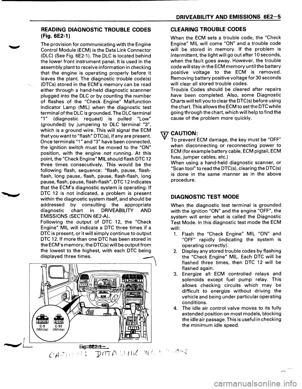
The provision for communicating with the Engine
Control Module (ECM) is the Data Link Connector
(DLC) (See Fig. 6E2-1 ). The DLC is located behind
the
lower front instrument panel. It is used in the
assembly plant
to receive information in checking
that the engine is operating properly before it
leaves the plant. The diagnostic trouble code(s)
(DTCs) stored in the ECM's memory can be read
either through a hand-held diagnostic scannner
plugged into the
DLC or by counting the number
of flashes of the "Check Engine" Malfunction
Indicator Lamp (MIL) when the diagnostic test
terminal
ofthe DLC is grounded. The DLC terminal
"1" (diagnostic request) is pulled "Low"
(grounded) by jumpering to DLC terminal "3",
which is a ground wire. This will signal the ECM
that you want to "flash" DTC(s), if any are present.
Once terminals "1" and "3" have been connected,
the ignition switch
must be moved to the "ON"
position, with the engine not running. At this
point, the
"Check Engine" MIL should flash DTC 12
three times consecutively. This
would be the
following flash, sequence: "flash, pause, flash
flash,
long pause, flash, pause, flash-flash, long
pause, flash, pause, flash-flash". DTC 12 indicates
that the ECM's diagnostic system is operating.
If
DTC 12 is not indicated, a problem is present
within the diagnostic system itself, and should be
addressed
by consulting the appropriate
diagnostic chart in
DRIVEABILITY AND
EMISSIONS (SECTION 6E2-A).
Following the output of DTC 12, the "Check
Engine" MIL
will indicate a DTC three times if a
DTC is present, or it will simply continue to output
DTC 12. If more than one DTC has been stored in
the
ECM's memory, the DTC(s) will be outputfrom
the lowest to the highest, with each DTC being
displayed three times.
--
Eig tU!2-1-...
DRIVEABILITY AND EMISSIONS 6E2-5
CLEARING TROUBLE CODES
When the ECM sets a trouble code, the "Check
Engine" MIL
will come "ON" and a trouble code
will be stored in memory. If the problem is
intermittent, the light
will go out after 10 seconds,
when the fault goes away. However, the trouble
code
will stay in the ECM memory until the battery
positive voltage
to the ECM is removed.
Removing battery positive voltage
for 30 seconds
will clear all stored trouble codes.
Trouble
Codes should be cleared after repairs
have been completed. Also, some Diagnostic
Charts will tell you to clear the DTC(s) before using
the chart. This
allows the ECM tosetthe DTCwhile
going through the chart, which will help to find the
cause
of the problem more quickly.
wcAUTION:
• To prevent ECM damage, the key must be "OFF"
when disconnecting or reconnecting power to
ECM (for example battery cable, ECM pigtail, ECM
fuse, jumper cables, etc.)
When using a hand-held diagnostic scanner,
or
"Scan tool" to read the DTC(s), clearing the DTC(s)
is done in the same manner as in the above
procedure.
DIAGNOSTIC TEST MODE
When the diagnostic test terminal is grounded
with the ignition "ON" and the engine "OFF", the
system
will enter what is called the Diagnostic
Test Mode.
In this diagnostic test mode the ECM
will:
1. Flash the "Check Engine" MIL "ON" and
"OFF" rapidly (indicating the system is
operating correctly).
2. Display any stored trouble codes by flashing
the
"Check Engine" MIL. Each DTC will be
flashed three times, then
DTC 12 will be
flashed again.
3. Energize all ECM controlled relays and
solenoids except
fuel pump relay. This
allows checking circuits which may be
difficult to energize without driving the
vehicle and being under particular operating
conditions.
4. The idle air control valve moves to its fully
extended position on most models, blocking
the
idle air passage. This is useful in checking
the
minimum idle speed.
Page 702 of 1928
6E2-6 DRIVEABILITY AND EMISSIONS
FIELD SERVICE MODE
ENGINE
CONTROL MODULE (ECM)
LEARNING ABILITY
The Engine Control Module (ECM) has a
"learning"
ability which allows it to make
corrections
for minor variations in the fuel system
to improve driveability. If the battery is
disconnected to clear diagnostic codes, or for
repair, the "learning" process has to begin all over
again. A change
may be noted in the vehicle's
performance. To "teach" the vehicle, make sure
the engine is at operating temperature, and drive
at part throttle, with moderate acceleration and
idle conditions, until normal performance returns.
lfthe diagnostic test terminal is grounded with the
engine running, the system is in
"Open" or
"Closed Loop".
In "Open Loop" the "Check Engine" malfunction
indicator lamp flashes
two and one-halftimes per
seconds.
In "Closed Loop", the light flashes once per
second.
Also, in "Closed
Loop", the light will stay "OFF"
most of the time if the system is too lean. It will
stay"ON" mostofthetime if the system is too rich.
While the system is in Field Service Mode, the
ECM will be in the following diagnostic test mode:
1. New trouble codes cannot be stored in the
ECM.
2. The closed loop timer is bypassed.
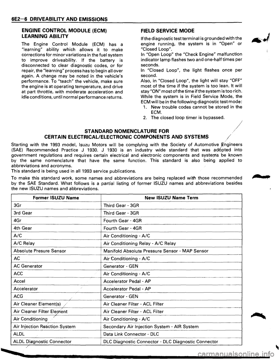
STANDARD NOMENCLATURE FOR /
CERTAIN ELECTRICAL/ELECTRONIC COMPONENTS AND SYSTEMS /
Starting with the 1993 model, lsuzu Motors will be complying with the Society of Automotive ~ngineers
(SAE) Recommended Practice J 1930. J 1930 is an industry wide standard that was ad6pted into
government regulations and requires certain electrical and electronic components and
syster;ns be known
by the same
nomenclature that have the same function. This standard is also being applied to
abbreviations and acronyms.
This standard is being used in
all 1993 service publications.
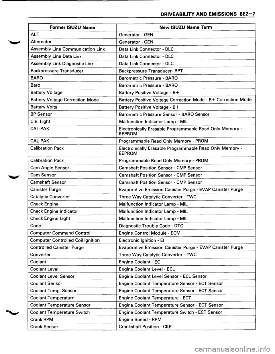
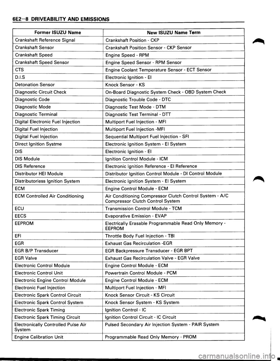
To make this standard work, some names and abbreviations are being replaced
with those recommended
by the
SAE Standard. What follows is a partial listing of former ISUZU names and abbreviations besides
the
new ISUZU names and abbreviations.
Former ISUZU Name New ISUZU Name Term
3Gr
Third Gear -3GR
3rd Gear
Third Gear -3GR
4Gr
Fourth Gear -4GR
4th Gear
Fourth Gear -4GR
A/C Air Conditioning -A/C
A/C
Relay Air Conditioning Relay -A/C Relay
Absolute Presure Sensor
Manifofd Absolute Pressure Sensor -MAP Sensor
AC Air Conditioning -A/C
AC Generator . Generator -GEN
ACC Air Conditioning -A/C
Accel
Accelerator Pedal -AP
Accelerator
Accelerator Pedal -AP
ACG Generator -GEN
Air Cleaner Element(s) / Air Cleaner Filter -ACL Filter
Air Cleaner Filter Ele;nent Air Cleaner Filter -ACL Filter
Air Conditioning / Air Conditioning -A/C
Air Injection Reaction System Secondary Air Injection System -AIR System
ALDL Data Link Connector -
DLC
ALDL Diagnostic Connector DLC Diagnostic Connector -DLC Diagnostic Connector ,.
, ....
Page 703 of 1928
DRIVEABILITY AND EMISSIONS 6E2-7
Former ISUZU Name New ISUZU Name Term
ALT Generator -GEN
Alternator
Generator -GEN
Assembly Line Communication Link
Data Link Connector -DLC
Assembly Line Data Link
Data Link Connector -DLC
Assembly Link Diagnostic Link
Data Link Connector -DLC
Backpressure Transducer
Backpressure Transducer-BPT
BARO Barometric Pressure -BARO
Baro
Barometric Pressure -BARO
Battery Voltage
Battery Positive Voltage-B+
Battery Voltage Correction Mode Battery Positive Voltage Correction Mode -B+ Correction Mode
Battery Volts
Battery
Positive Voltage-B+
BP Sensor Barometric Pressure Sensor -BARO Sensor
C.E. Light
Malfunction Indicator Lamp -MIL
CAL-PAK Electronically
Erasable Programmable Read Only Memory -
EEPROM
CAL-PAK
Programmable Read Only Memory -PROM
Calibration Pack Electronically Erasable Programmable Read Only Memory -
EEPROM
Calibration Pack
Programmable Read Only Memory-PROM
Cam Angle Sensor Camshaft Position Sensor -CMP Sensor
Cam Sensor Camshaft Position Sensor -CMP Sensor
Camshaft Sensor Camshaft Position Sensor -CMP Sensor
Canister Purge Evaporative Emission Canister Purge-EVAP Canister Purge
Catalytic Converter
Three Way Catalytic Converter-TWC
Check Engine
Malfunction
Indicator Lamp -MIL
Check Engine Indicator Malfunction Indicator Lamp -MIL
Check Engine Light
Malfunction Indicator Lamp-MIL
Code Diagnostic Trouble Code -DTC
Computer Command Control Engine Control Module -ECM
Computer Controlled Coil Ignition Electronic Ignition -El
Controlled Canister Purge Evaporative Emission Canister Purge-EVAP Canister Purge
Converter Three Way Catalytic Converter -TWC
Coolant Engine Coolant -EC
Coolant Level
Engine Coolant Level -ECL
Coolant Level Sensor Engine Coolant Level Sensor -ECL Sensor
Coolant Sensor Engine Coolant Temperature Sensor -ECT Sensor
Coolant Temp. Sensor Engine Coolant Temperature Sensor-ECT Sensor
Coolant Temperature Engine Coolant Temperature -ECT
Coolant Temperature Sensor Engine Coolant Temperature Sensor-ECT Sensor
Coolant Temperature Switch Engine Coolant Temperature Switch -ECT Sensor
Crank RPM Engine Speed -RPM
Crank Sensor Crankshaft Position-CKP
Page 704 of 1928
6E2-8 DRIVEABILITY AND EMISSIONS
Former ISUZU Name New ISUZU Name Term
Crankshaft Reference Signal Crankshaft Position -CKP
Crankshaft Sensor
Crankshaft Position Sensor -CKP Sensor
Crankshaft Speed
Engine Speed -
RPM
Crankshaft Speed Sensor
Engine Speed Sensor -RPM Sensor
CTS Engine Coolant Temperature Sensor -ECT Sensor
D.I.S Electronic Ignition -El
Detonation Sensor
Knock Sensor-KS
Diagnostic Circuit Check On-Board Diagnostic System Check -OBD System Check
Diagnostic Code Diagnostic Trouble Code -DTC
Diagnostic Mode
Diagnostic Test Mode-DTM
Diagnostic Terminal
Diagnostic Test Terminal -DTT
Digital Electronic
Fuel Injection Multipart Fuel Injection -MFI
Digital Fuel Injection Multipart Fuel Injection -MFI
Digital Fuel Injection Sequential Multipart Fuel Injection -SFI
Direct Ignition Systme Electronic Ignition System -El System
DIS Electronic Ignition -El
DIS Module
Ignition Control Module -ICM
DIS Reference Electronic Ignition Reference -El Reference
Distributor
HEI Module Distributor Ignition Control Module -Dl Control Module
Distributorless Ignition System Electronic Ignition System -
El System
ECM Engine Control Module -ECM
ECM Controlled Air Conditioning Air Conditioning Compressor Clutch Control System -A/C
Compressor Clutch Control System
ECU Transmission Control Module -TCM
EECS Evaporative Emission-EVAP
EEPROM Electrically Erasable Programmable Read Only Memory-
EEPROM
EFI Throttle Body Fuel Injection -TBI
EGR Exhaust Gas Recirculation -EGR
EGR B/P Transducer EGR Backpressure Transducer -EGR BPT
EGR Valve Exhaust Gas Recirculation Valve -EGR Valve
Electronic Control Module Engine Control Module -ECM
Electronic Control Unit Powertrain Control Module -PCM
Electronic Engine Control Module Engine Control Module -ECM
Electronic Fuel Injection Multipart Fuel Injection -MFI
Electronic Spark Control Circuit Knock Sensor Circuit -KS Circuit
Electronic Spark Control System Knock Sensor System -KS System
Electronic Spark Timing Ignition
Control -IC
Electronic Spark Timing Circuit Ignition Control Circuit -IC Circuit
Electronically Controlled Pulse
Air Pulsed Secondary Air Injection System -PAIR System
System
Engine
Calibration Unit Programmable Read Only Memory -PROM
•
Page 705 of 1928
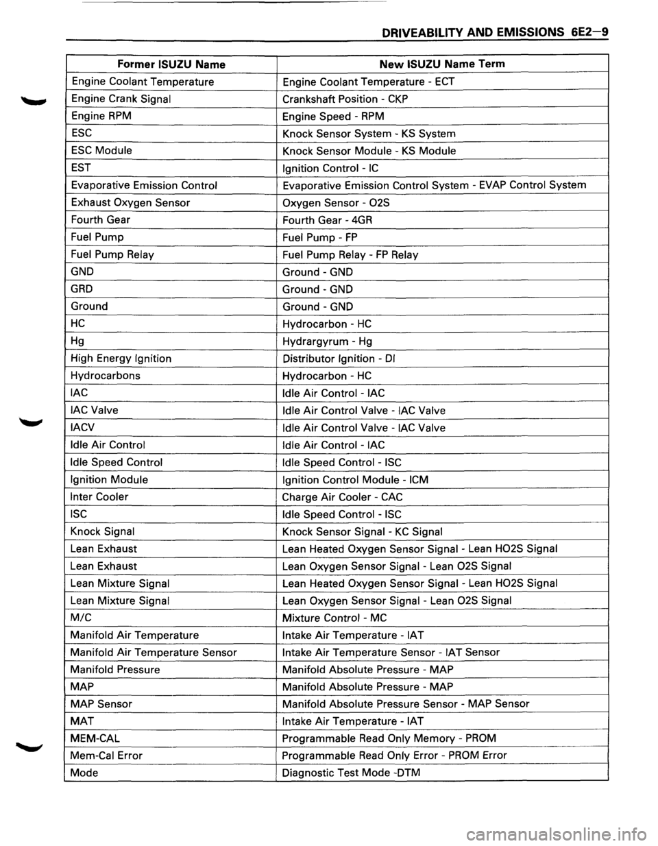
DRIVEABILITY AND EMISSIONS 6E2-9
Former ISUZU Name New ISUZU Name Term
Engine Coolant Temperature
Engine Coolant Temperature -ECT
Engine Crank Signal Crankshaft Position -CKP
Engine RPM Engine Speed -RPM
ESC Knock Sensor System-KS System
ESC Module Knock Sensor Module -KS Module
EST Ignition Control -IC
Evaporative Emission Control Evaporative Emission Control System -EVAP Control System
Exhaust Oxygen Sensor
Oxygen Sensor -
02S
Fourth Gear
Fourth Gear -4GR
Fuel Pump Fuel Pump -FP
Fuel Pump Relay
Fuel Pump Relay -FP Relay
GND Ground-GND
GAD Ground-GND
Ground Ground-GND
HC Hydrocarbon -HC
Hg Hydrargyrum-Hg
High Energy Ignition Distributor Ignition -Dl
Hydrocarbons
Hydrocarbon -HC
lAC
Idle Air Control-lAC
lAC Valve
Idle
Air Control Valve-lAC Valve
IACV Idle
Air Control Valve -lAC Valve
Idle
Air Control Idle Air Control -lAC
Idle
Speed Control Idle Speed Control -ISC
Ignition Module
Ignition Control Module -ICM
Inter Cooler Charge Air Cooler -CAC
ISC Idle Speed Control -ISC
Knock Signal Knock Sensor Signal -KC Signal
Lean Exhaust
Lean Heated Oxygen Sensor Signal -Lean H02S Signal
Lean Exhaust
Lean Oxygen Sensor Signal -Lean 02S Signal
Lean Mixture Signal Lean Heated Oxygen Sensor Signal -Lean H02S Signal
Lean Mixture Signal Lean Oxygen Sensor Signal -Lean 02S Signal
M/C Mixture Control -MC
Manifold Air Temperature Intake Air Temperature-IAT
Manifold
Air Temperature Sensor Intake Air Temperature Sensor-IAT Sensor
Manifold Pressure Manifold Absolute Pressure -MAP
MAP
Manifold Absolute Pressure -MAP
MAP Sensor
Manifold Absolute Pressure Sensor -MAP Sensor
MAT Intake Air Temperature-IAT
MEM-CAL Programmable Read Only Memory -PROM
Mem-Cal Error Programmable Read Only Error -PROM Error
Mode Diagnostic
Test Mode -DTM
Page 706 of 1928
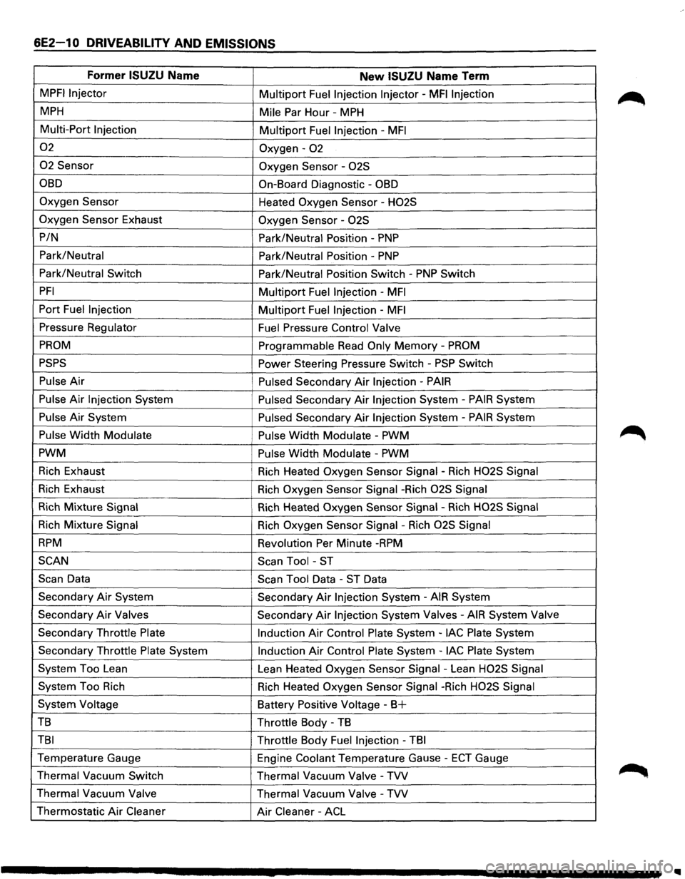
6E2-10 DRIVEABILITY AND EMISSIONS
Former ISUZU Name New ISUZU Name Term
MPFI Injector Multiport Fuel Injection Injector -MFI Injection
MPH Mile Par Hour -MPH
Multi-Port Injection
Multiport Fuel Injection -MFI
02 Oxygen-02
02 Sensor Oxygen Sensor -02S
OBD On-Board Diagnostic -OBD
Oxygen Sensor
Heated Oxygen Sensor -H02S
Oxygen
Sensor Exhaust Oxygen Sensor -02S
P/N
Park/Neutral Position -PNP
Park/Neutral
Park/Neutral Position -PNP
Park/Neutral Switch Park/Neutral Position Switch -PNP Switch
PFI Multiport Fuel Injection -MFI
Port Fuel Injection Multiport Fuel Injection -MFI
Pressure Regulator
Fuel Pressure Control Valve
PROM Programmable Read Only Memory -PROM
PSPS Power Steering Pressure Switch-PSP Switch
Pulse Air Pulsed Secondary Air Injection -PAIR
Pulse Air Injection System Pulsed Secondary Air Injection System -PAIR System
Pulse Air System Pulsed Secondary Air Injection System -PAIR System
Pulse Width Modulate Pulse Width Modulate -PWM
PWM Pulse
Width Modulate -PWM
Rich Exhaust
Rich Heated Oxygen Sensor Signal -Rich H02S Signal
Rich Exhaust
Rich Oxygen Sensor Signal -Rich 02S Signal
Rich Mixture Signal Rich Heated Oxygen Sensor Signal -Rich H02S Signal
Rich Mixture Signal Rich Oxygen Sensor Signal -Rich 02S Signal
RPM Revolution Per Minute -RPM
SCAN
Scan Tool -ST
Scan Data Scan Tool Data -ST Data
Secondary
Air System Secondary Air Injection System -AIR System
Secondary
Air Valves Secondary Air Injection System Valves -AIR System Valve
Secondary Throttle Plate
Induction Air Control Plate System -lAC Plate System
Secondary Throttle
Plate System Induction Air Control Plate System -lAC Plate System
System Too Lean
Lean Heated
Oxygen Sensor Signal -Lean H02S Signal
System Too Rich
Rich Heated Oxygen Sensor Signal -Rich H02S Signal
System Voltage Battery Positive Voltage -B+
TB Throttle Body -TB
TBI Throttle Body Fuel Injection -TBI
Temperature Gauge
Engine Coolant Temperature Gause -ECT Gauge
Thermal Vacuum Switch
Thermal Vacuum
Valve -TVV
Thermal Vacuum Valve Thermal Vacuum Valve -TVV
Thermostatic Air Cleaner Air Cleaner -ACL
Page 707 of 1928
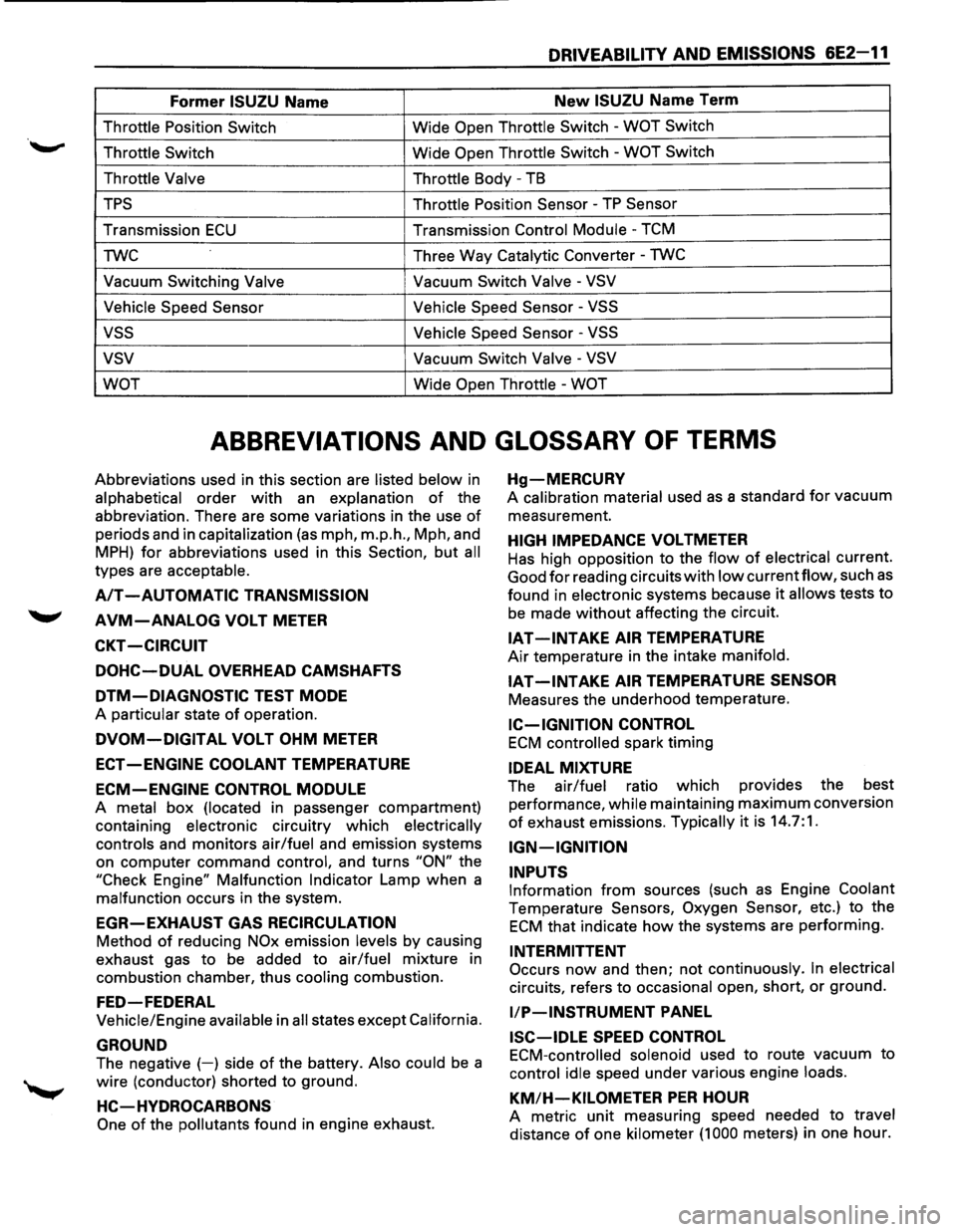
DRIVEABILITY AND EMISSIONS 6E2-11
Former ISUZU Name New ISUZU Name Term
Throttle Position Switch Wide Open Throttle Switch -WOT Switch
Throttle Switch
Wide Open Throttle Switch -WOT Switch
Throttle Valve Throttle
Body -TB
TPS Throttle Position Sensor -TP Sensor
Transmission ECU Transmission Control Module -TCM
TWC Three
Way
Catalytic Converter -TWC
Vacuum Switching Valve Vacuum Switch Valve -VSV
Vehicle Speed Sensor Vehicle
Speed Sensor
-VSS
vss Vehicle Speed Sensor -VSS
vsv Vacuum Switch Valve -VSV
WOT
Wide Open Throttle -WOT
ABBREVIATIONS AND GLOSSARY OF TERMS
Abbreviations used in this section are listed below in
alphabetical order with an explanation of the
abbreviation. There are some variations in the use
of
periods and in capitalization (as mph, m.p.h., Mph, and
MPH) for abbreviations used in this Section, but all
types are acceptable.
A/T -AUTOMATIC TRANSMISSION
AVM-ANALOG VOLT METER
CKT -CIRCUIT
DOHC-DUAL OVERHEAD CAMSHAFTS
DTM-DIAGNOSTIC TEST MODE
A particular state of operation.
DVOM-DIGITAL VOLT OHM METER
ECT -ENGINE COOLANT TEMPERATURE
ECM-ENGINE CONTROL MODULE
A metal box (located in passenger compartment)
containing
electronic circuitry which electrically
controls
and monitors air/fuel and emission systems
on
computer command control, and turns "ON" the
"Check Engine"
Malfunction Indicator Lamp when a
malfunction occurs in the system.
EGR-EXHAUST GAS RECIRCULATION
Method of reducing NOx emission levels by causing
exhaust gas
to be added to air/fuel mixture in
combustion chamber, thus
cooling combustion.
FED-FEDERAL
Vehicle/Engine available in all states except California.
GROUND
The negative (-) side of the battery. Also could be a
wire (conductor) shorted to ground.
HC-HVDROCARBONS
One of the pollutants found in engine exhaust.
Hg-MERCURV
A calibration material used as a standard for vacuum
measurement.
HIGH IMPEDANCE VOLTMETER
Has high opposition to the flow of electrical current.
Good
for reading circuits with low currentflow, such as
found in electronic systems because it allows tests to
be made without affecting the circuit.
IAT -INTAKE AIR TEMPERATURE
Air temperature in the intake manifold.
IAT-INTAKE AIR TEMPERATURE SENSOR
Measures the underhood temperature.
IC-IGNITION CONTROL
ECM controlled spark timing
IDEAL MIXTURE
The air/fuel ratio which provides the best
performance,
while maintaining maximum conversion
of exhaust emissions. Typically it is 14.7:1.
IGN-IGNITION
INPUTS
Information from sources (such as Engine Coolant
Temperature Sensors, Oxygen Sensor, etc.) to the
ECM that indicate how the systems are performing.
INTERMITTENT
Occurs now and then; not continuously. In electrical
circuits, refers to occasional open, short, or ground.
liP-INSTRUMENT PANEL
ISC-IDLE SPEED CONTROL
ECM-controlled solenoid used to route vacuum to
control idle speed under various engine loads.
KM/H-KILOMETER PER HOUR
A metric unit measuring speed needed to travel
distance of one kilometer (1 000 meters) in one hour.
Page 708 of 1928
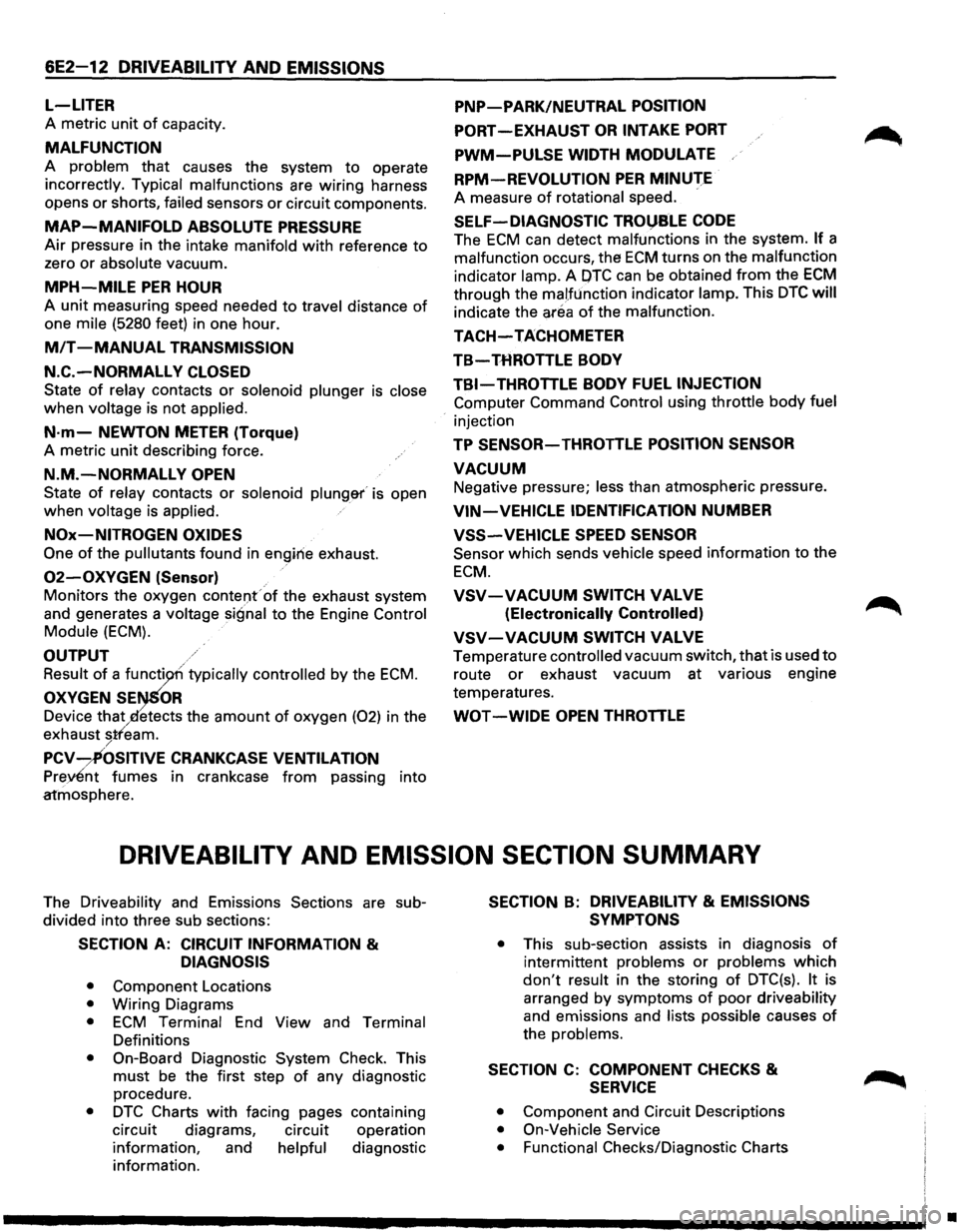
6E2-12 DRIVEABILITY AND EMISSIONS
L-LITER
A metric unit of capacity.
MALFUNCTION
A problem that causes the system to operate
incorrectly. Typical malfunctions are wiring harness
opens
or shorts, failed sensors or circuit components.
MAP-MANIFOLD ABSOLUTE PRESSURE
Air pressure in the intake manifold with reference to
zero or absolute vacuum.
MPH-MILE PER HOUR
A unit measuring speed needed to travel distance of
one mile (5280 feet) in one hour.
MIT -MANUAL TRANSMISSION
N.C.-NORMALLY CLOSED
State of relay contacts or solenoid plunger is close
when voltage is not applied.
N·m-NEWTON METER (Torque)
A metric unit describing force.
N.M.-NORMALLY OPEN
State of relay contacts or solenoid plung&r' is open
when voltage is applied.
NOx-NITROGEN OXIDES
One of the pullutants found in engirie exhaust.
02-0XYGEN (Sensor)
Monitors the oxygen contel)f of the exhaust system
and generates a
voltage signal to the Engine Control
Module (ECM).
OUTPUT
Result of a functi typically controlled by the ECM.
OXYGEN SE OR
Device that etects the amount of oxygen (02) in the
exhaust
stfeam. /
PCV-~OSITIVE CRANKCASE VENTILATION
Prey£nt fumes in crankcase from passing into
atmosphere.
PNP-PARK/NEUTRAL POSITION
PORT-EXHAUST OR INTAKE PORT
PWM-PULSE WIDTH MODULATE
RPM-REVOLUTION PER MINUTE
A measure of rotational speed.
SELF-DIAGNOSTIC TROl)SLE CODE
The ECM can detect malfunctions in the system. If a
malfunction occurs, the ECM turns on the malfunction
indicator lamp. A OTC can be obtained from the ECM
through the malfunction indicator lamp. This DTC will
indicate the area of the malfunction.
TACH-TACHOMETER
TB-THROTTLE BODY
TBI-THROTTLE BODY FUEL INJECTION
Computer Command Control using throttle body fuel
injection
TP SENSOR-THROTTLE POSITION SENSOR
VACUUM
Negative pressure; less than atmospheric pressure.
VIN-VEHICLE IDENTIFICATION NUMBER
VSS-VEHICLE SPEED SENSOR
Sensor which sends vehicle speed information to the
ECM.
VSV-VACUUM SWITCH VALVE
(Electronically Controlled)
VSV-VACUUM SWITCH VALVE
Temperature controlled vacuum switch, that is used to
route or exhaust vacuum at various engine
temperatures.
WOT -WIDE OPEN THROTTLE
DRIVEABILITV AND EMISSION SECTION SUMMARY
The Driveability and Emissions Sections are sub
divided into three sub sections:
SECTION A: CIRCUIT INFORMATION &
DIAGNOSIS
• Component Locations
• Wiring Diagrams
• ECM Terminal End View and Terminal
Definitions
• On-Board Diagnostic System Check. This
must be the first step of any diagnostic
procedure.
• DTC Charts with facing pages containing
circuit diagrams, circuit operation
information, and
helpful diagnostic
information.
SECTION B: DRIVEABILITY & EMISSIONS
SYMPTONS
• This sub-section assists in diagnosis of
intermittent problems or problems which
don't result in the storing of DTC(s). It is
arranged
by symptoms of poor driveability
and emissions and lists possible causes of
the problems.
SECTION C: COMPONENT CHECKS &
SERVICE
• Component and Circuit Descriptions
• On-Vehicle Service
• Functional
Checks/Diagnostic Charts
•
Page 709 of 1928
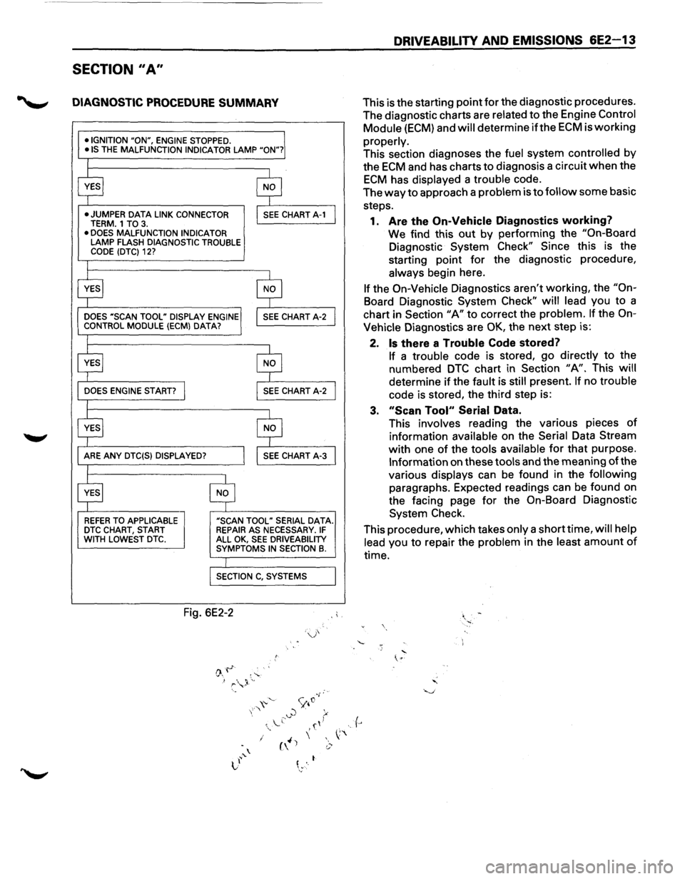
SECTION II A"
DIAGNOSTIC PROCEDURE SUMMARY
•IGNITION "ON", ENGINE STOPPED. •IS THE MALFUNCTION INDICATOR LAMP "ON"?
•
JUMPER DATA LINK CONNECTOR TERM. 1 TO 3. • DOES MALFUNCTION INDICATOR LAMP FLASH DIAGNOSTIC TROUBLE CODE (DTC) 12?
REFER TO APPLICABLE DTC CHART, START WITH LOWEST DTC.
"SCAN TOOL" SERIAL DATA. REPAIR AS NECESSARY. IF ALL OK, SEE DRIVEABILITY SYMPTOMS IN SECTION B.
Fig. 6E2-2
r
DRIVEABILITY AND EMISSIONS 6E2-13
This is the starting point for the diagnostic procedures.
The diagnostic charts are
related to the Engine Control
Module
(ECM) and will determine if the ECM is working
properly.
This section diagnoses the fuel system controlled by
the
ECM and has charts to diagnosis a circuit when the
ECM has displayed a trouble code.
The
way to approach a problem is to follow some basic
steps.
1.
Are the On-Vehicle Diagnostics working?
We find this out by performing the "On-Board
Diagnostic System Check" Since this is the
starting point
for the diagnostic procedure,
always
begin here.
If the On-Vehicle Diagnostics aren't working, the "On
Board Diagnostic System Check" will lead you to a
chart in Section
"A" to correct the problem. If the On
Vehicle
Diagnostics are OK, the next step is:
2.
Is there a Trouble Code stored?
If a trouble code is stored, go directly to the
numbered
DTC chart in Section "A". This will
determine if the fault is still present. If no trouble
code is stored, the third step is:
3. "Scan Tool" Serial Data.
This
involves reading the various pieces of
information available on the Serial Data Stream
with one of the tools available for that purpose.
Information on these tools and the meaning of the
various
displays can be found in the following
paragraphs. Expected readings can be found on
the facing page
for the On-Board Diagnostic
System Check.
This procedure, which takes
only a short time, will help
lead
you to repair the problem in the least amount of
time.
Page 710 of 1928
6E2-14 DRIVEABILITY AND EMISSIONS
DATA LINK CONNECTOR ''SCAN TOOLS''
The Engine Control Module (ECM) can communicate a
variety
of information through data link connector
terminal
"2". This data is transmitted at a high frequecy
which requires a
"Scan tool" for interpretation. There
are several
"Scan tools" available for reading this
information.
With an understanding
of the data which the tool
displays, and knowledge of the circuits involved, the
tool can be
very useful in obtaining information which
would be more difficult or impossible to obtain with
other equipment.
"Scan tools" do not make the use of diagnostic charts
unnecessary, nor
can they indicate exactly where a
problem is in a particular circuit. Trouble Tree
Charts
incorporate diagnosis procedures using a "Scan tool"
where possible and most charts require the use of a
"Scan tool" when it is applicable.
A "SCAN TOOL" THAT DISPLAYS FAUL TV
DATA SHOULD NOT BE USED AND THE
PROBLEM SHOULD BE REPORTED TO THE
MANUFACTURER. THE USE OF A FAUL TV
"SCAN TOOL" CAN RESULT IN MIS
DIAGNOSIS
AND UNNECESSARY PARTS
REPLACEMENT.
ECM's have two (2) modes for transmitting
information. The
following information will describe
the system operation in each
of the modes.
Data List (FO)
On engines that can be monitored in the "Open"
mode, certain parameters can be observed
without changing the engine operating
characteristics. The parameters capable
of being
read vary with engine families.
Most "Scan tools"
are programmed so that the system will go
directly into the data link connector mode
if the
"Open" mode is not available.
''SCAN TOOL'' LIMITATIONS AND USE
The "Scan tool" allows a quick check of sensors
and switches which are inputs
to the ECM. The
"Scan tool" allows one to manipulate wiring
harnesses or components under the hood while
observing the "Scan Tool" readout. This helps in
locating intermittents
with the engine not
running.
INTERMITTENT CONDITIONS
The "Scan tool" is helpful in cases of intermittent
operation. The
tool can be plugged in and
observed while driving the vehicle under the
condition
where the light comes "ON" momen- tarily,
or the
engine driveability is poor
momentarily.
If the problem seems to be related
to certain areas
that can be checked on the "Scan ~
tool", then those are the positions that should be
checked while driving the vehicle. If there does
not seem to
be any correlation between the
problem and any specific circuit, the
"Scan tool"
can be checked on each position, watching for a
period
of time to see if there is any change in the
readings that indicates intermittent operation.
The
"Scan tool" is also a useful and quick way of
comparing operating parameters of a poorly
operating engine with a known good one. For
example; A sensor may shift in
value but not set a
diagnostic trouble code. Comparing with a known
good vehicle may uncover the problem.
The
"Scan tool" has the ability to save time in
diagnosis and prevent the replacement
of good
parts. The key to using the
"Scan tool" success
fully
for diagnosis lies in the technicians ability to
understand the system he is trying to diagnose as
well as an understanding of the "Scan tool's"
limitations. Therefore, the technician should read
the tool operating manual to become familiar
with
the tool. The following information will describe
most of the "Scan tool" positions and how they
can be helpful in diagnosis.
"SCAN TOOL" POSITIONS
INJECTOR PULSE WIDTH
In this position, the reading is given in milli
seconds which is the on time that the ECM is
commanding to the injector(s).
CLOSED LOOP/OPEN LOOP
This position will indicate whether the engine
control system
is operating in open or closed
loop. Most systems go closed loop after a certain
amount of run time, when engine coolant
temperature
is high enough, and the oxygen
sensor becomes active.
TROUBLE CODES
Will display any trouble codes stored in the ECM
memory.
THROTTLE POSITION (TP) SENSOR
Values read will be the voltage as seen by the ~
ECM. The voltage should be the TP sensor
specification
with the throttle closed and go up to
about 5 volts with
wide open throttle.
•