ECO mode ISUZU TROOPER 1995 Repair Manual
[x] Cancel search | Manufacturer: ISUZU, Model Year: 1995, Model line: TROOPER, Model: ISUZU TROOPER 1995Pages: 1928
Page 1017 of 1928
AUTOMATIC TRANSMISSION (4L30-E) 7 A-145
TCM PRECAUTONS
The TCM can be damaged by:
(1) The Electrostatic discharge
(2) The short circuit of some terminals to voltage
or to ground.
Electrostatic Discharge Damage Description:
(1) Electronic components used to control systems
are often designed
to carry very low voltage,
and are
very susceptible to damage caused by
electrostatic discharge. It is possible for less
than 100 volts of static electricity to cause
damage
to some electronic components. By
comparison,
it takes as much as 4000 volts for
a person to even feel the zap of a static
discharge.
(2) There are several
ways for a person to become
statically charged. The most common methods
of charging are by friction and induction. An
example
of charging by friction is a person
sliding across a car seat, in
which a charge of
as much as 25,000 volts can build up.
Charging
by induction occurs when a person
with well insulated shoes stands near a highly
charged object and momentarily touches
ground. Charges for the same polarity are
drained off, leaving the person
highly charged
with the opposite polarity. Static charges of
either type can cause damage, therefore, it is
important to use care when handling and
testing electronic components.
NOTICE: To prevent possible Electrostatic
Discharge damage:
(1) Do not touch the TCM connector pins or
soldered components on the TCM circuit
board.
(2) When handling a Mem-Cal (PROM), do not
touch the component leads, and do not
remove integrated circuit from carrier.
(3) Be sure to follow the guidelines listed below if
servicing any of these electronic components:
(4) Do not open the replacement part package
until
it is time to install the part.
(5)
Avoid touching electrical terminals of the part.
(6) Before removing the part from its package,
ground the package to a known good ground
on the vehicle.
(7) Always touch a known good ground before
handling the part. This step should be repeated
before installing
the part if the part has been
handled
while sliding across the seat, while
sitting down from a standing position or while
walking some distance.
INFORMATION ON TCM:
(1) The Transmission Control Module (TCM) is
located in the
driver compartment and is the
control center
of the electronic transmission
control system.
(2) The TCM must be maintained at a temperature
below 185°F (85°C) at all times. This is most
essential if the vehicle is put through a paint
baking process. The
TCM will become in
operative
if its temperature exceeds 85°C
(185°F). Therefore, it is recommended that the
TCM be removed or that temporary insulation
be placed around the
TCM during the time the
vehicle is in a paint oven
or other high
temperature process.
(3) The
TCM is designed to process the various
inputs and then respond by sending the
appropriate electrical signals
to control trans
mission upshift,
downshift, shift feel and
torque converter clutch engagement.
(4) The TCM constantly interprets information
from the various sensors, and controls the
systems
that affect transmission and vehicle
performance. By analyzing operational prob
lems, the
TCM is able to perform a diagnostic
function
by displaying DTC(s) and aid the
technician in making repairs.
PROM/MEM-CAL:
(1) Information for a specific engine and vehicle is
programmed using an integrated circuit called
a Programmable Read-Only
Memory (PROM).
It
is also called a MEM-CAL (Memory Cali
brator). This allows one model of controller to
be used for many different vehicles. The
PROM is located inside the TCM and has
information on the engine, transmission,
calibration., etc. While one
TCM part number
can be used by many vehicle lines, a PROM is
more specific and must be used only with the
right vehicles. For this reason, it is very
important to check the latest parts book and
Service Bulletin
information for the correct part
number when replacing a PROM.
Page 1018 of 1928
7A-146 AUTOMATIC TRANSMISSION (4L30-E)
INTERMITTENT CONDITIONS
If the TECH1 displays a diagnostic trouble code as
intermittent, or if after a test drive a DTC does not
reappear though the detection conditions for this
DTC are present: the problem is most likely a faulty
electrical connection or loose wiring. Terminals
and
grounds should always be the prime suspect.
lntermittents rarely occur inside sophisticated
electronic components such
as the TCM.
Use the
DTC information to understand which wires
and sensors are involved.
When an
intermittent problem is encountered,
check suspect circuits for:
(1) Poor terminal to wire connection.
(2) Terminals not fully seated in the connector
body (backed out).
(3) Improperly formed or damaged terminals.
(4) Loose, dirty, or corroded ground connections:
HINT: Any time you have an intermittent in
more than one circuit, check whether the circuits
share a
common ground connection.
(5) Pinched or damaged wires.
(6) Electro-Magnetic Interference (EMI):
HINT:
Check that all wires are properly routed
away from spark plug wires, distributor wires,
coil, and generator. Also check
for improperly
installed electrical options, such as lights, 2-way
radios, etc. Use
the
F3: SNAPSHOT mode of the TECH 1 to help
isolate the cause
of an intermittent fault. The
snapshot
mode will record information before and
after the problem occurs. Set the snapshot
to
"trigger" on the suspect DTC or, if you notice the
reported
symptom during test drive, trigger the
snapshot
manually.
(1) NOTE: When TECH1 is plugged the shifts are
always
done at the maximum pressure. This
means
that if you do SNAPSHOT while driving
you will! notice firm shifts.
After the snapshot has been triggered, command
the TECH1 to play back the flow of data recorded
from each of the various sensors. Signs of an
intermittent fault in a sensor circuit are sudden
unexplainable jump in data values out of the
normal range.
CASE:
problem still not solved GOTO TCM MEM
CAL REPLACEMENT.
•
Page 1019 of 1928
AUTOMATIC TRANSMISSION (4L30-E) 7A-147
TCM MEM-CAL REPLACEMENT
(TCM: Transmission Control Module)
1. MEM-CAL (Memory and Calibration Unit)
Information for specific transmission and vehicle is
programmed using an integrated circuit called a
MEM-CAL.
This allows one model of controller to be used for
many different vehicles.
The MEM-CAL is located inside the TCM and has
information on the transmission, shift map, etc.
several others.
2. MEM-CAL Replacement
If the diagnostic procedures require MEM-CAL
replacement,
the MEM-CAL should be replaced
using the following procedures.
NOTICE:
The ignition must be "OFF", when disconnecting or
reconnecting the TCM connector, to prevent
internal damage to the TCM.
NOTICE:
To prevent possible Electrostatic Discharge damage
to the TCM, do not touch the connector pins or
soldered components on the circuit board.
MEM-CAL Replacement Procedure:
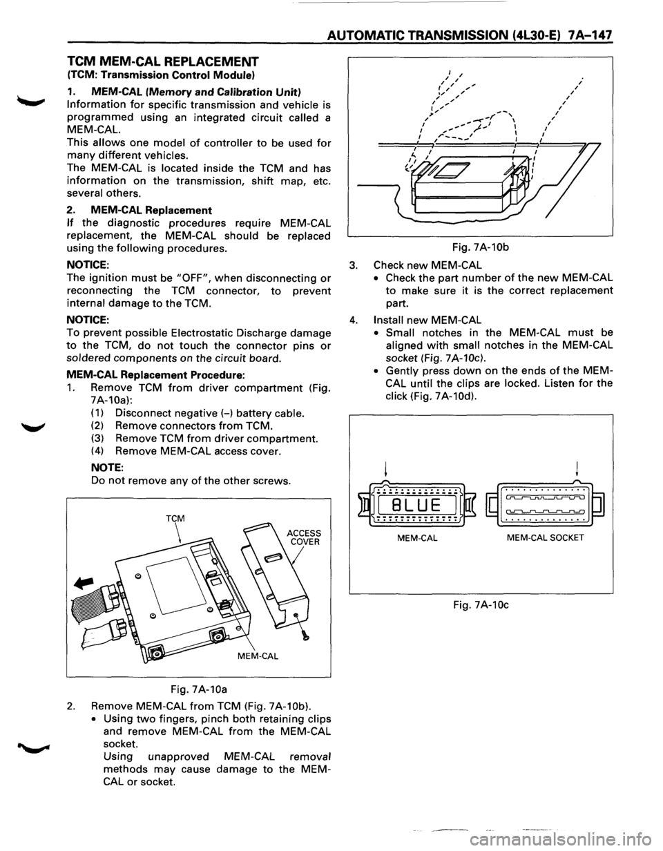
1. Remove TCM from driver compartment (Fig.
7A-10a):
( 1) Disconnect negative (-) battery cable.
(2) Remove connectors from TCM.
(3) Remove TCM from driver compartment.
(4) Remove MEM-CAL access cover.
NOTE:
Do not remove any of the other screws.
Fig.
7A-10a
2. Remove MEM-CAL from TCM (Fig. 7A-10b).
•
Using two fingers, pinch both retaining clips
and remove MEM-CAL from the MEM-CAL
socket.
Using unapproved
methods may cause
CAL or socket.
MEM-CAL removal
damage to the MEM- Fig.
7A-10b
3. Check new MEM-CAL
• Check
the part number of the new MEM-CAL
to make sure it is the correct replacement
part.
4. Install new MEM-CAL
• Small notches in the MEM-CAL must be
aligned with small notches in the MEM-CAL
socket (Fig.
7A-10c).
• Gently
press down on the ends of the MEM
CAL
until the clips are locked. Listen for the
click (Fig. 7A-10d).
! !
($I~rn~ ~~~) . . . . . . . . . . . . . . . ............ .
MEM-CAL MEM-CAL SOCKET
Fig. 7A-10c
Page 1030 of 1928
7A-158 AUTOMATIC TRANSMISSION (4L30-E)
1. Mode switch cover
2.
Selector lever
• Disconnect selector lever from the mode
switch.
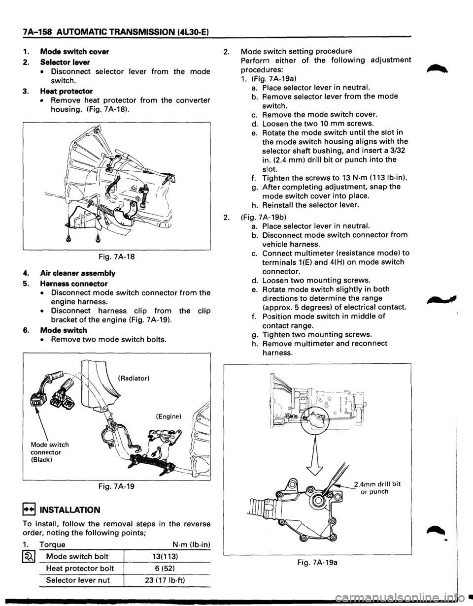
3. Heat protector
• Remove heat protector from the converter
housing. (Fig. 7A-18).
Fig. 7A-18
4. Air cleaner assembly
5. Harness connector
• Disconnect mode switch connector from the
engine harness.
• Disconnect harness clip from the clip
bracket ofthe engine (Fig. 7A-19).
6. Mode switch
• Remove two mode switch bolts.
Mode switch
connector
(Black)
(Radiator)
(Engine)
Fig. 7A-19
I••! INSTALLATION
To install, follow the removal steps in the reverse
order,
noting the following points;
1. Torque
~~~ Mode switch bolt
Heat protector bolt
Selector lever nut
N·m Ob·in)
13(113)
6 (52)
23 ( 17 lb·ft)
2. Mode switch setting procedure
Perform either
of the following adjustment
procedures:
1. (Fig. 7A-19a)
a. Place selector lever in neutral.
b. Remove selector lever from the mode
switch.
c. Remove the mode switch cover.
d. Loosen the
two 10 mm screws.
e. Rotate the mode switch until the slot in
the mode switch housing aligns with the
selector shaft bushing, and insert a 3/32
in. (2.4
mm) drill bit or punch into the
sllot.
f. Tighten the screws to 13 N·m (113 lb·in).
g. After completing adjustment, snap the
mode switch cover into place.
h. Reinstall the selector lever.
2. (Fig. 7 A.-19b)
a. Place selector lever in neutral.
b. Disconnect mode switch connector from
vehicle harness.
c. Connect multimeter (resistance mode) to
terminals 1(E) and 4(H) on mode switch
connector.
d.
Loosen two mounting screws.
e. Rotate mode switch slightly in both
diirections to determine the range
(approx.
5 degrees) of electrical contact.
f. Position
mode switch in middle of
contact range.
g. Tighten
two mounting screws.
h. Remove multimeter and reconnect
harness.
Fig. 7A-19a
..
•
Page 1079 of 1928
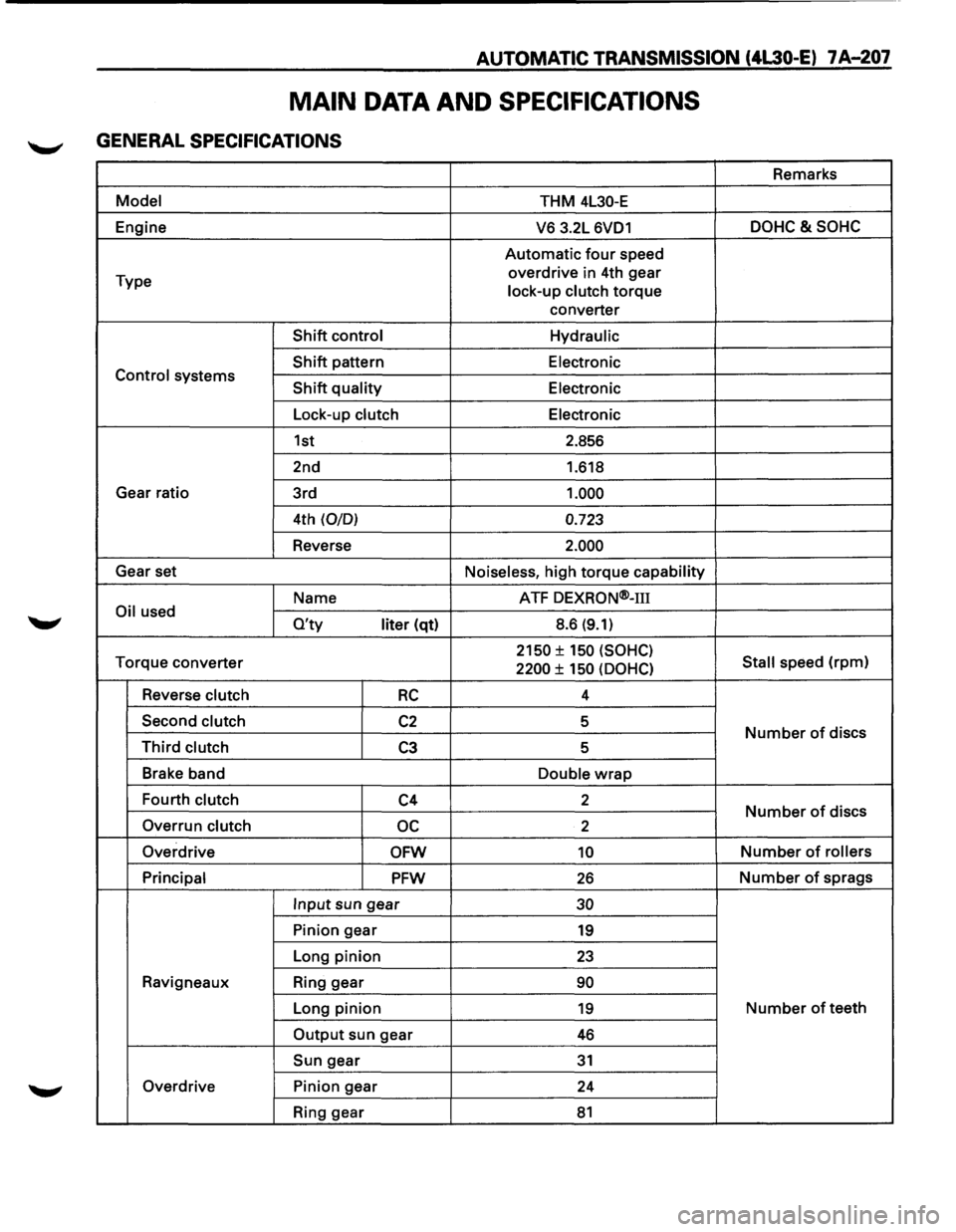
AUTOMATIC TRANSMISSION (4L30-E) 7 A-207
MAIN DATA AND SPECIFICATIONS
GENERAL SPECIFICATIONS
Remarks
Model THM 4L30-E
Engine
V6 3.2L 6VD1 DOHC&SOHC
Automatic four speed
Type overdrive
in 4th gear
lock-up clutch
torque
converter
Shift control Hydraulic
Shift pattern
Electronic Control systems Shift quality Electronic
Lock-up clutch Electronic
1st 2.856
2nd 1.618
Gear ratio
3rd
1.000
4th (0/0) 0.723
Reverse 2.000
Gear set
Noiseless, high torque capability
Name ATF
DEXRON®-m
Oil used O'ty liter (qt) 8.6 (9.1)
Torque
converter 2150 ± 150 (SOHC)
Stall speed (rpm) 2200 ± 150 (OOHC)
Reverse clutch RC 4
Second clutch
C2 5 Number of discs Third clutch C3 5
Brake band
Double
wrap
Fourth clutch C4 2 Number of discs
Overrun clutch oc 2
Overdrive
OFW 10 Number of rollers
Principal
PFW 26 Number of sprags
Input sun gear 30
Pinion gear 19
Long pinion 23
Ravigneaux Ring gear 90
Long pinion 19 Number of teeth
Output sun gear 46
Sun gear 31
Overdrive Pinion gear
24
Ring gear
81
Page 1467 of 1928
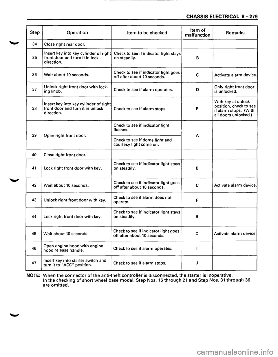
------------- -
CHASSIS ELECTRICAL 8-279
Step Operation Item to be checked Item of Remarks
malfunction
34 Close right rear door.
Insert key into key cylinder of right
Check to see if indicator light stays 35 front door and turn it in lock on steadily. B direction.
36 Wait about 10 seconds. Check
to see if indicator light goes c Activate alarm device. off after about 10 seconds.
37 Unlock right front door with lock-Check to see if alarm operates. D Only right front door ing knob.
is unlocked.
Insert
key into key cylinder of right With
key at unlock
position, check to see 38 front door and turn it in unlock Check to see if alarm stops E if alarm stops. (With
direction.
all doors unlocked.)
Check to see if indicator light flashes.
39 Open right front door.
A
Check to
see if dome light and
courtesy light come on.
40 Close right front door.
Check to
see if indicator light stays 41 Lock right front door with key.
on steadily. B
42 Wait about 10 seconds. Check
to see if indicator light goes c Activate alarm device. off after about 10 seconds.
43 Unlock right front door with key. Check
to see if alarm does not F operate.
Check to
see if indicator light stays 44 Lock right front door with key.
on steadily. B
45 Wait about 10 seconds. Check
to see if indicator light goes c Activate alarm device. off after about 10 seconds.
46 Open engine hood with engine
Check to see if alarm operates. I hood release handle.
47 Insert key into starter switch and
Check to see if alarm stops. J turn it to "ACC" position.
NOTE: When the connector of the anti-theft controller is disconnected, the starter is inoperative.
In the checking of short wheel base model, Step Nos. 16 through 21 and Step Nos. 31 through 36
are omitted.