ECO mode ISUZU TROOPER 1995 Owner's Manual
[x] Cancel search | Manufacturer: ISUZU, Model Year: 1995, Model line: TROOPER, Model: ISUZU TROOPER 1995Pages: 1928
Page 881 of 1928
AUTOMATIC TRANSMISSION (4L30·E) 7A-9
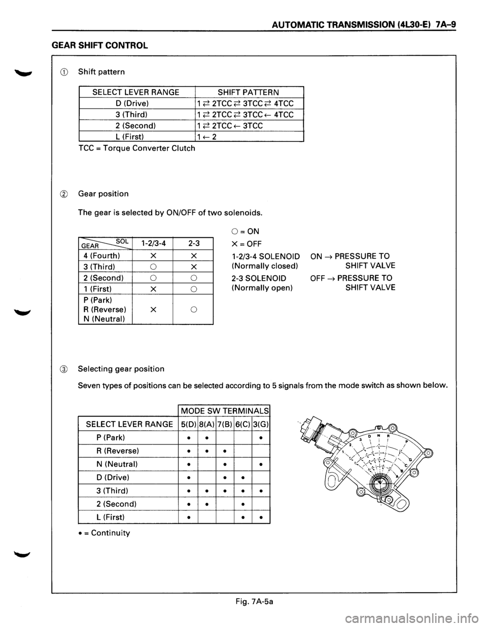
GEAR SHIFT CONTROL
CD Shift pattern
SELECT
LEVER RANGE SHIFT PATTERN
D (Drive)
1
~ 2TCC ~ 3TCC ~ 4TCC
3 (Third)
1 ~ 2TCC ~ 3TCC f-4TCC
2 (Second)
1 ~ 2TCC f-3TCC
L (First) 1f-2
TCC =Torque Converter Clutch
® Gear position
The gear is selected by ON/OFF of two solenoids.
G~ 1-2/3-4
4 (Fourth)
X
3 (Third)
0
2 (Second) 0
1 (First)
X
P (Park)
R (Reverse)
X
N
(Neutral)
@ Selecting
gear position
2-3
X
X
0
0
0
0=0N
X=OFF
1-2/3-4 SOLENOID
(Normally closed)
2-3 SOLENOID
(Normally open)
ON ~ PRESSURE TO
SHIFT
VALVE
OFF~ PRESSURE TO
SHIFT VALVE
Seven types
of positions can be selected according to 5 signals from the mode switch as shown below.
MODE
SW TERMINALS
SELECT LEVER RANGE 5(D)
8(A) 7(8) 6(C) 3(G)
P (Park)
• • •
R (Reverse) • • •
N (Neutral) • • •
D (Drive) • • •
3 (Third) • • • • •
2 (Second) • • •
L (First) • • •
• =Continuity
Fig. 7A-5a
Page 882 of 1928
7A-10 AUTOMATIC TRANSMISSION (4L30-E)
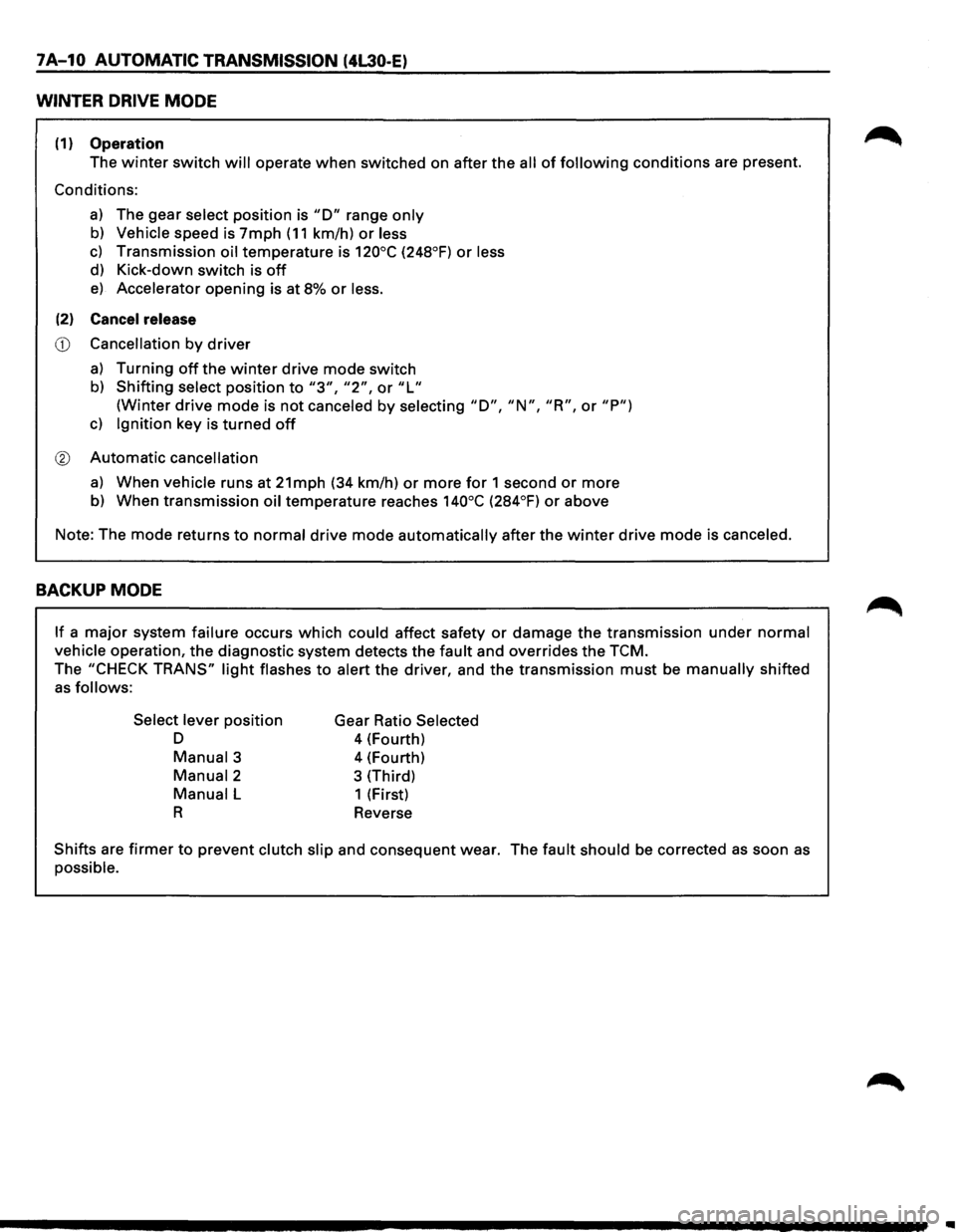
WINTER DRIVE MODE
(1) Operation
The winter switch will operate when switched on after the all of following conditions are present.
Conditions:
a) The gear select position is "D" range only
b) Vehicle speed is 7mph (11 km/h) or less
c) Transmission oil temperature is 120°C (248°F) or less
d) Kick-down switch is off
e) Accelerator opening is at 8% or less.
(2) Cancel release
CD Cancellation by driver
a) Turning off the winter drive mode switch
b) Shifting select position to "3", "2", or "L"
(Winter drive mode is not canceled by selecting "D", "N", "R", or "P")
c) Ignition key is turned off
® Automatic cancellation
a) When vehicle runs at 21mph (34 km/h) or more for 1 second or more
b) When transmission oil temperature reaches 140°C (284°F) or above
Note: The mode returns
to normal drive mode automatically after the winter drive mode is canceled.
BACKUP MODE
If a major system failure occurs which could affect safety or damage the transmission under normal
vehicle operation, the diagnostic system detects the fault and overrides the TCM.
The "CHECK TRANS" light flashes to alert the driver, and the transmission must be manually shifted
as follows:
Select lever
position
D
Manual3
Manual2
Manual L
R
Gear Ratio Selected
4 (Fourth)
4 (Fourth)
3 (Third)
1 (First)
Reverse
Shifts are firmer to prevent clutch slip and consequent wear. The fault should be corrected as soon as
possible.
Page 895 of 1928
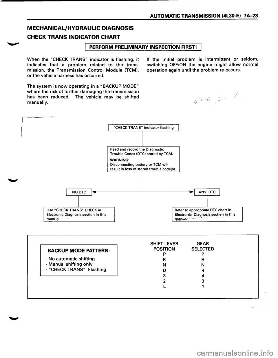
MECHANICAL/HYDRAULIC DIAGNOSIS
CHECK TRANS INDICATOR CHART
AUTOMATIC TRANSMISSION (4L30-E) 7 A-23
I PERFORM PRELIMINARY INSPECTION FIRST!
When the "CHECK TRANS" indicator is flashing, it
indicates that a problem related to the trans
mission, the Transmission Control
Module (TCM),
or the vehicle harness has occurred:
The system is
now operating in a "BACKUP MODE"
where the risk of further damaging the transmission
has been reduced. The vehicle may be shifted
manually.
If the initial problem is intermittent or seldom,
switching OFF/ON the engine might allow normal
operation again until the problem re-occurs.
I "CHECK TRANS" indicator flashing
I NO DTC I
I
Use "CHECK TRANS" CHECK in
Electronic Diagnosis section in this
manual
BACKUP MODE PATTERN:
-No automatic shifting
- Manual shifting only
-"CHECK TRANS" Flashing
Read and record the Diagnostic
Trouble Codes {DTCI stored by TCM.
WARNING: Disconnecting battery or TCM will result in loss of stored trouble code{s).
I ANY DTC J
I
Refer to appropriate DTC chart in
Electronic Diagnosis sectien in this
l'lUl,IUiah~ c " • •• "
SHIFT LEVER GEAR
POSITION p
R
N
D
3
2
L
SELECTED p
R
N
4
4
3
1
Page 907 of 1928
AUTOMATIC TRANSMISSION (4L30-E) 7 A-35
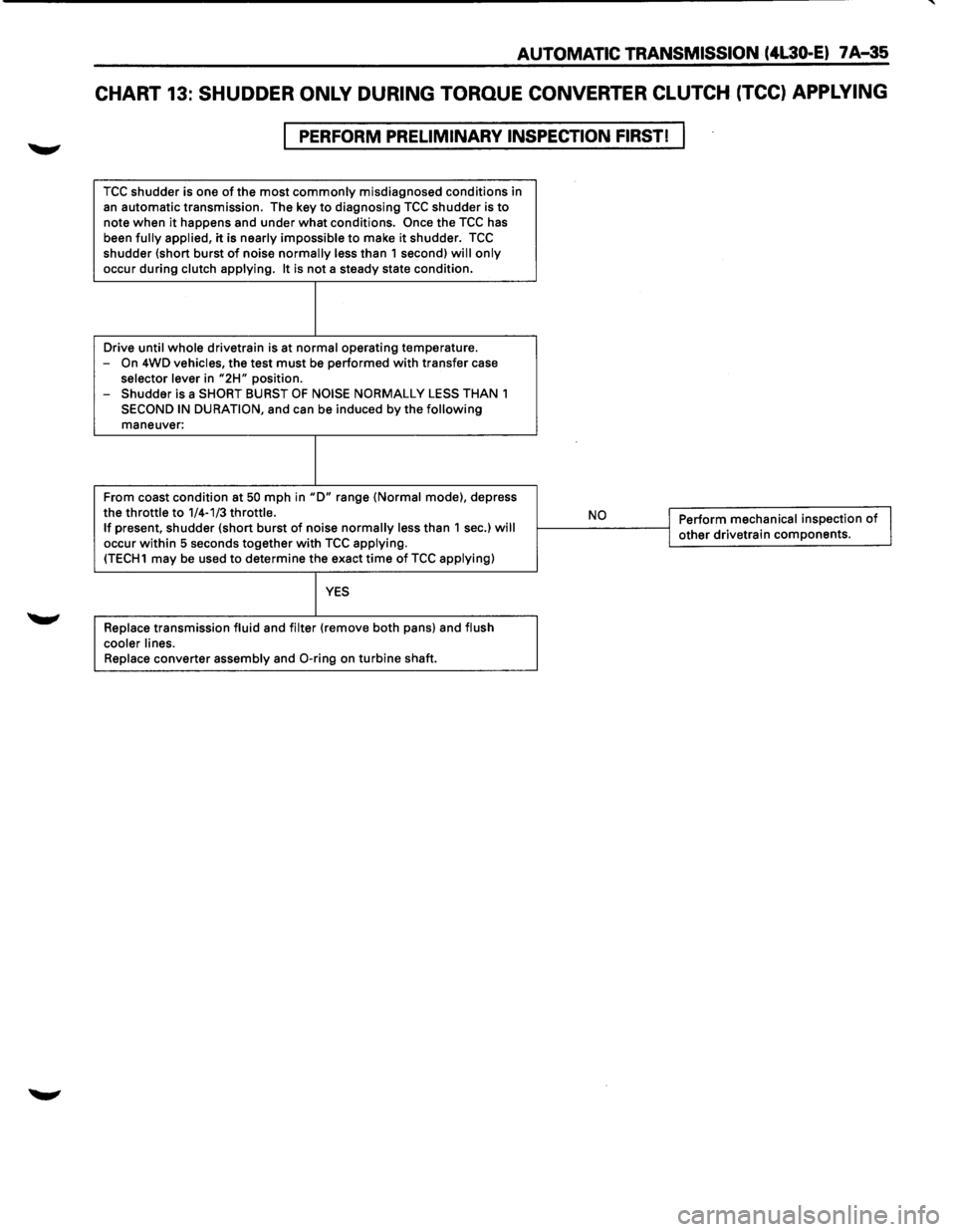
CHART 13: SHUDDER ONLY DURING TORQUE CONVERTER CLUTCH (TCC) APPLYING
PERFORM PRELIMINARY INSPECTION FIRST!
TCC shudder is one of the most commonly misdiagnosed conditions in
an automatic transmission. The key to diagnosing TCC shudder is to note when it happens and under what conditions. Once the TCC has
been fully applied, it is nearly impossible to make it shudder. TCC shudder {short burst of noise normally less than 1 second) will only
occur during clutch applying. It is not a steady state condition.
Drive
until whole drivetrain is at normal operating temperature.
-On 4WD vehicles, the test must be performed with transfer case selector lever in "2H" position.
- Shudder is a SHORT BURST OF NOISE NORMALLY LESS THAN 1
SECOND IN DURATION, and can be induced by the following maneuver:
From coast condition at
50 mph in "D" range {Normal mode), depress
the throttle to 1/4-1/3 throttle. If present, shudder {short burst of noise normally less than 1 sec.) will occur within 5 seconds together with TCC applying. {TECH1 may be used to determine the exact time of TCC applying)
YES
Replace transmission fluid and filter {remove both pans) and flush
cooler lines.
Replace
converter assembly and 0-ring on turbine shaft.
,__ __ N_o ___ ---<1 Perform mechanical inspection of I j other drivetrain components.
Page 914 of 1928
7 A-42 AUTOMATIC TRANSMISSION (4L30-E)
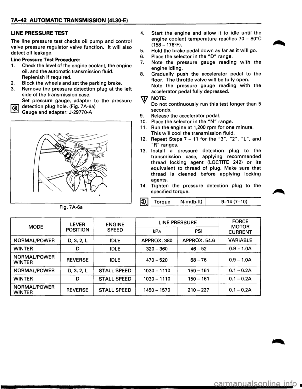
LINE PRESSURE TEST
The line pressure test checks oil pump and control
valve
pressure regulator valve function. It will also
detect oil leakage.
Line Pressure Test Procedure:
1. Check the level of the engine coolant, the engine
oil, and the automatic transmission fluid.
Replenish
if required.
2. Block the wheels and set the parking brake.
3. Remove the pressure detection plug at the left
side of the transmission case.
Set pressure gauge, adapter
to the pressure
l"iC\1 detection plug hole. (Fig. 7 A-6a)
~ Gauge and adapter: J-29770-A
Fig. 7A-6a
LEVER ENGINE
MODE
POSITION
SPEED
NORMAL/POWER D,3,2, L IDLE
WINTER D IDLE
NORMAL/POWER REVERSE IDLE WINTER
NORMAL/POWER
D,3,2,L STALL SPEED
WINTER D STALL SPEED
NORMAL/POWER REVERSE STALL SPEED WINTER
4.
5.
6.
7.
8.
9.
10.
11.
Start the engine and allow it to idle until the
engine
coolant temperature reaches 70 -80°C
(158-176°F).
Hold
the brake pedal down as far as it will go.
Place the selector in the "D" range.
Note the pressure gauge reading
with the
engine
idling.
Gradually
push the accelerator pedal to the
floor. The throttle valve will be fully open.
Note the pressure gauge reading
with the
accelerator
pedal fully depressed.
NOTE:
Do not continuously run this test longer than 5
seconds.
Release the accelerator pedal.
Place
the selector in the "N" range.
Run the engine at
1,200 rpm for one minute.
This
will cool the transmission fluid.
12. Repeat Steps 7-11 for the "3", "2", "L", and
"R" ranges.
13.
Install a pressure detection plug to the
transmission case,
applying recommended
thread
locking agent (LOCTITE 242) or its
equivalent to thread
of plug. Make sure that
thread is cleaned before applying locking
agents.
14. Tighten the pressure detection plug to the
specified torque.
~~~ Torque N·mOb·ft) / 9-14 (7-10)
LINE
PRESSURE FORCE
MOTOR kPa PSI CURRENT
APPROX. 380 APPROX. 54.6 VARIABLE
320-360 46-52 0.9 -1.0A
470-520 68-76 0.9 -1.0A
1030-1110 150-161 0.1-0.2A
1030-1110 150-161 0.1-0.2A
1450-1570 210-227 0.1-0.2A
•
Page 915 of 1928
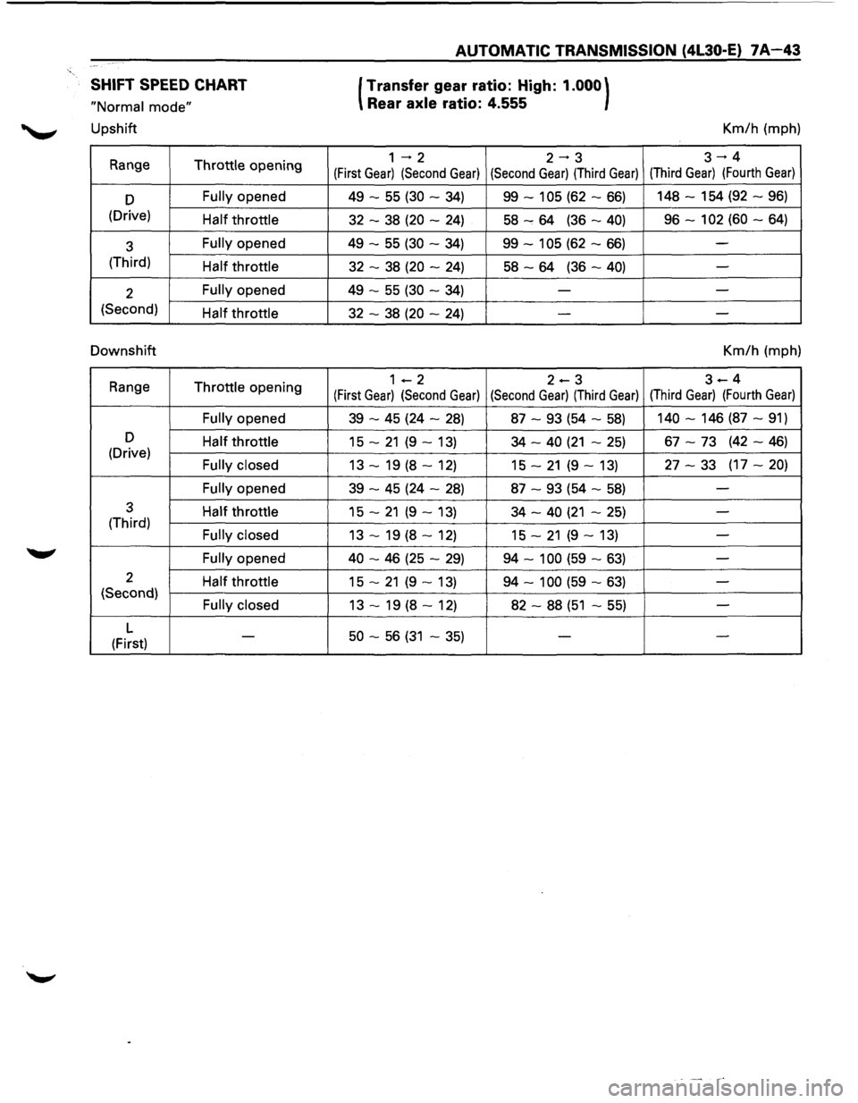
SHIFT SPEED CHART
"Normal mode"
Upshift
Range Throttle opening
D Fully opened
(Drive) Half throttle
3 Fully opened
(Third) Half throttle
2 Fully opened
(Second) Half throttle
Downshift
Range Throttle opening
Fully opened
D Half throttle (Drive) Fully closed
Fully
opened
3 Half throttle (Third) Fully closed
Fully
opened
2 Half throttle (Second) Fully closed
L -(First)
AUTOMATIC TRANSMISSION (4L30-E) 7A-43
(Transfer
gear ratio: High: 1.000)
Rear axle ratio: 4.555
1 ..... 2 2--3
(First Gear) (Second Gear) (Second Gear) (Third Gear)
49 -55 (30 -34) 99-105 (62-66)
32 -38 (20 -24) 58......, 64 (36-40)
49 -55 (30 -34) 99-105 (62-66)
32 -38 (20 -24) 58-64 (36-40)
49 -55 (30 -34) -
32 -38 (20 -24) -
1-2 2-3
(First Gear) (Second Gear) (Second Gear) (Third Gear)
39 -45 (24 -28) 87 -93 (54 -58)
15 -21 (9 -13)
34 -40 (21 -25)
13 -19 (8 -12) 15 -21 (9 -13)
39 -45 (24 -28) 87 -93 (54 -58)
15 -21 (9 -13) 34 -40 (21 -25)
13 -19 (8 -12) 15 -21 (9 -13)
40 -46 (25 -29) 94-100 (59-63)
15 -21 (9 -13) 94-100 (59-63)
13 -19 (8 -12) 82 -88 (51 -55)
50 -56 (31 -35) -
Km/h (mph)
3-+4
(Third Gear) (Fourth Gear)
148-154 (92-96)
96-102 (60-64)
-
-
-
-
Km/h (mph)
3-4
(Third Gear) (Fourth Gear)
140-146 (87-91)
67 -73 (42-46)
27 -33 (17-20)
-
-
-
-
- -
-
Page 916 of 1928
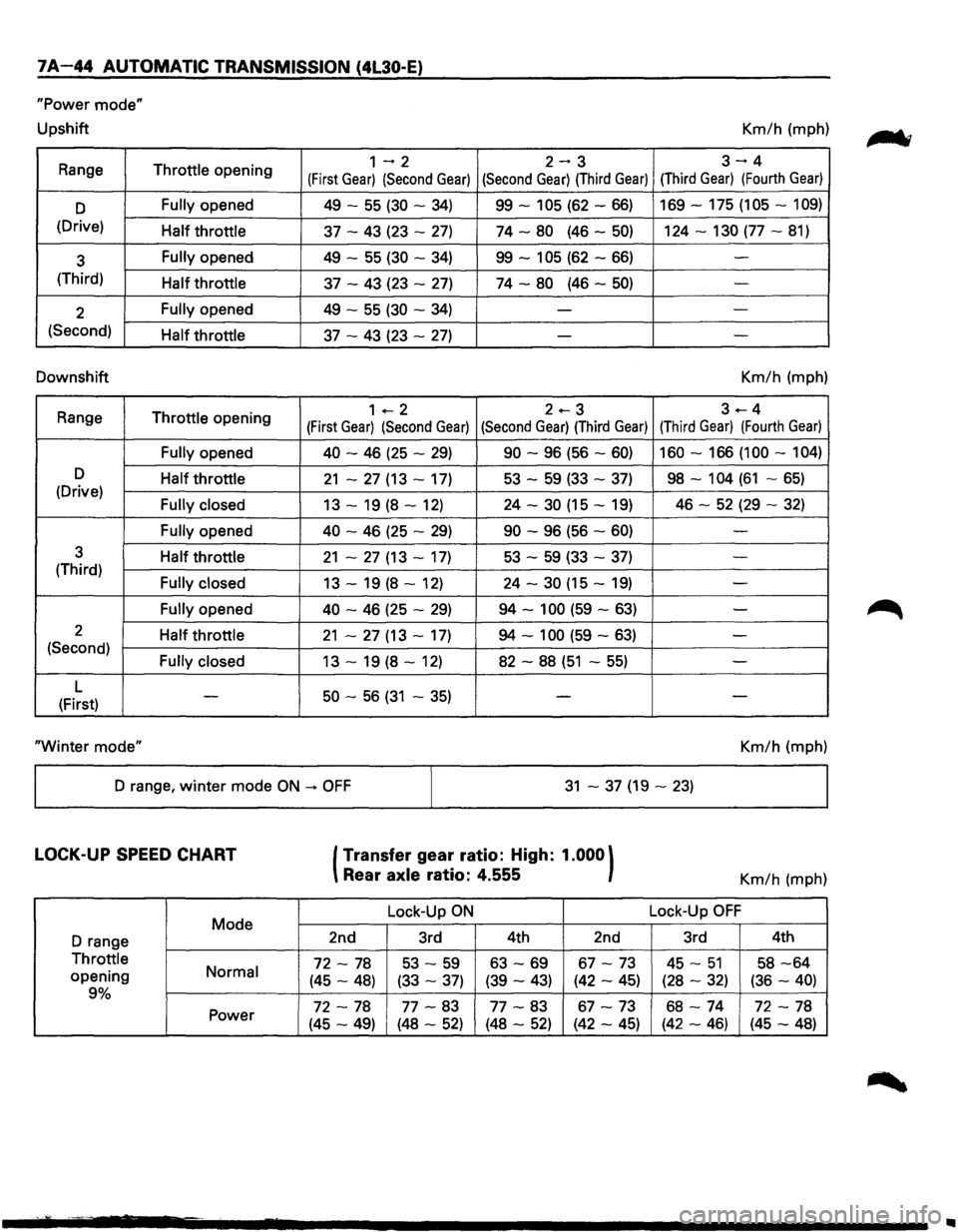
7A-44 AUTOMATIC TRANSMISSION (4l30-E)
"Power mode"
Upshift Km/h (mph)
Range
Throttle opening 1-2 2-3 3-4
(First Gear) (Second Gear) (Second Gear) (Third Gear) (Third Gear) (Fourth Gear)
D Fully opened 49 -55 (30 -34) 99-105 (62-66) 169-175 (105-109)
(Drive) Half throttle 37 -43 (23 -27) 74-80 (46-50) 124-130 (77-81)
3 Fully opened
49 -55 (30 -34) 99-105 (62-66) -
(Third) Half throttle 37 -43 (23 -27) 74-80 (46-50) -
2 Fully opened
49 -55 (30 -34) --
(Second) Half throttle 37 -43 (23 -27) - -
Downshift Km/h (mph)
Range
Throttle opening 1 +--2 2.-3 3---4
(First Gear) (Second Gear) (Second Gear) (Third Gear) (Third Gear) (Fourth Gear)
Fully opened 40
-46 (25 -29) 90 -96 (56 -60) 160-166 (100-104)
D Half throttle 21 -27 (13 -17) 53 -59 (33 -37) 98-104 (61 -65) (Drive) Fully closed 13 -19 (8 -12) 24 -30 (15 -19) 46 -52 (29 -32)
Fully opened 40
-46 (25 -29) 90 -96 (56 -60) -
3 Half throttle 21 -27 (13 -17) 53 -59 (33 -37) -(Third) Fully closed 13 -19 (8 -12) 24 -30 (15 -19) -
Fully opened 40 -46 (25 -29) 94-100 (59-63) -
2 Half throttle 21 -27 (13 -17) 94-100 (59-63) -(Second) Fully closed 13 -19 (8 -12) 82 -88 (51 -55) -
L 50 -56 (31 -35) (First) -
--
"Winter
mode" Km/h (mph)
D range,
winter mode ON -+ OFF 31 -37 (19-23)
LOCK-UP SPEED CHART
Mode
D range
Throttle
opening Normal
9%
Power
(Transfer
gear ratio: High: 1.000)
Rear axle ratio: 4.555
Lock-Up ON
2nd 3rd 4th 2nd
72-78 53 -59 63-69 67-73
(45-48) (33-37) (39-43) (42-45)
72-78 77-83 77-83 67-73
(45-49) (48-52) (48-52) (42-45)
Km/h (mph)
Lock-Up
OFF
3rd 4th
45-51 58-64
(28-32) (36-40)
68-74 72-78
(42-46) (45-48)
..
Page 920 of 1928
7 A-48 AUTOMATIC TRANSMISSION (4L30-E)
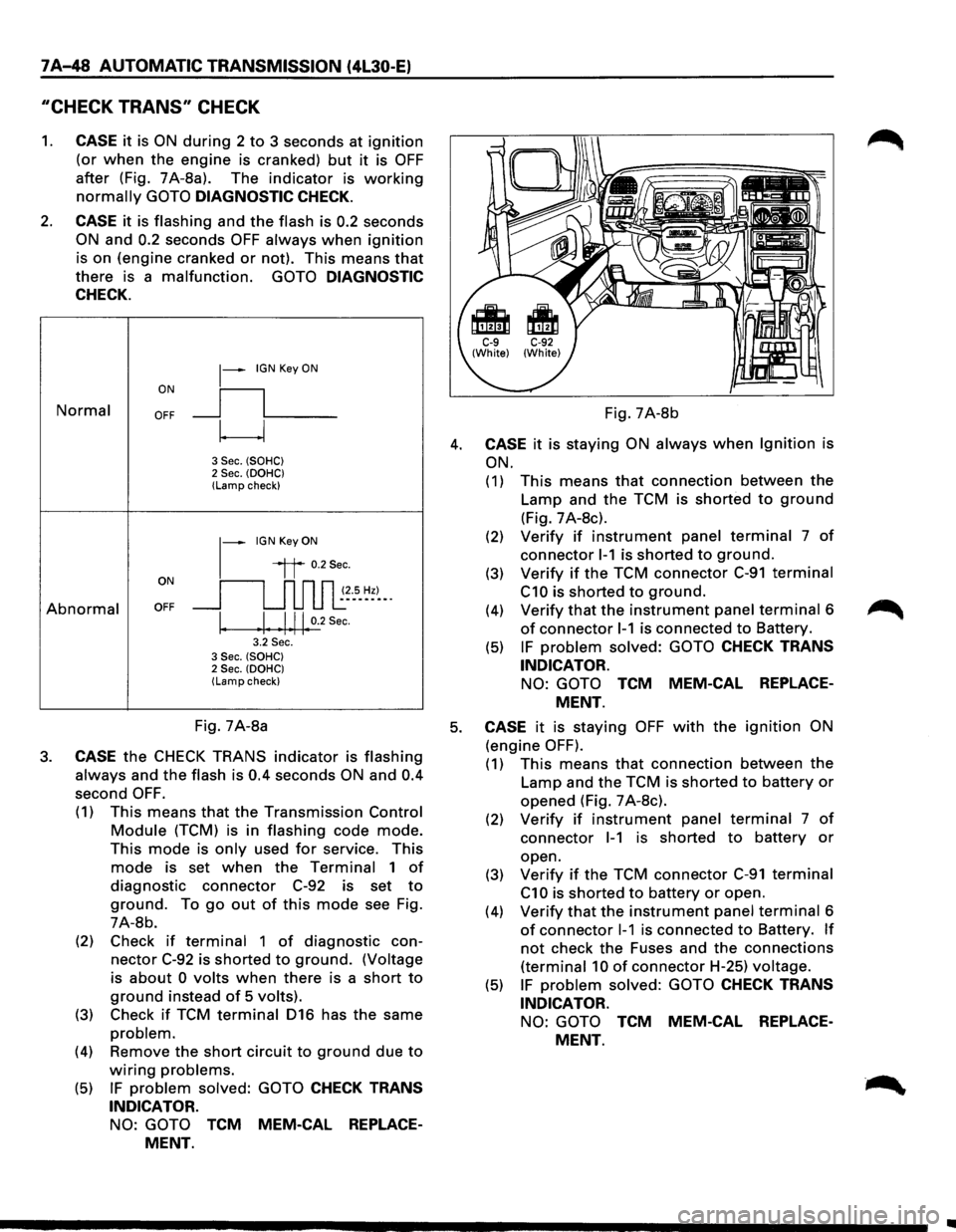
"CHECK TRANS" CHECK
1. CASE it is ON during 2 to 3 seconds at ignition
(or when the engine is cranked) but it is OFF
after (Fig. 7A-8a). The indicator is working
normally GOTO DIAGNOSTIC CHECK.
2. CASE it is flashing and the flash is 0.2 seconds
ON and 0.2 seconds OFF always when ignition
is on (engine cranked or not). This means that
there is a malfunction. GOTO DIAGNOSTIC
CHECK.
Normal
Abnormal
~-IGN Key ON
ON
II
OFF __j l___
~
3 Sec. (SOHC) 2 Sec. (OOHC) (Lamp check)
1-
IGN Key ON
il 0.2Sec.
oN 11 n n n ~~--s_ ~~)-_. OFF __j u u u l:
I. .I. .1.11. 0.2
Sec.
3.2 Sec. 3 Sec. (SOHC) 2 Sec. (OOHC) (Lamp check)
Fig. 7A-8b
4. CASE it is staying ON always when Ignition is
ON.
(1) This means that connection between the
Lamp and the TCM is shorted to ground
(Fig. 7 A-8c).
(2) Verify if instrument panel terminal 7 of
connector 1-1 is shorted to ground.
(3) Verify if the TCM connector C-91 terminal
C10 is shorted to ground.
(4) Verify that the instrument panel terminal 6
of connector 1-1 is connected to Battery.
(5) IF problem solved: GOTO CHECK TRANS
INDICATOR.
NO: GOTO TCM MEM-CAL REPLACE
MENT.
Fig. 7A-8a 5. CASE it is staying OFF with the ignition ON
(engine OFF). 3. CASE the CHECK TRANS indicator is flashing
always and the flash is 0.4 seconds ON and 0.4
second OFF.
(1) This means that the Transmission Control
Module (TCM) is in flashing code mode.
This mode is only used for service. This
mode is set when the Terminal 1 of
diagnostic connector C-92 is set to
ground. To go out of this mode see Fig.
7A-8b.
(2) Check
if terminal 1 of diagnostic con
nector C-92 is shorted to ground. (Voltage
is
about 0 volts when there is a short to
ground instead of 5 volts).
(3) Check if TCM terminal 016 has the same
problem.
(4) Remove the short circuit to ground due to
wiring problems.
(5) IF problem solved: GOTO CHECK TRANS
INDICATOR.
NO: GOTO TCM MEM-CAL REPLACE
MENT.
(1) This means that connection between the
Lamp and the TCM is shorted to battery or
opened (Fig. 7 A-8c).
(2) Verify if instrument panel terminal 7 of
connector 1-1 is shorted to battery or
open.
(3)
Verify if the TCM connector C-91 terminal
C1 0 is shorted to battery or open.
(4)
Verify that the instrument panel terminal 6
of connector 1-1 is connected to Battery. If
not check the Fuses and the connections
(terminal 10 of connector H-25) voltage.
(5) IF problem solved: GOTO CHECK TRANS
INDICATOR.
NO: GOTO TCM MEM-CAL REPLACE
MENT.
Page 946 of 1928
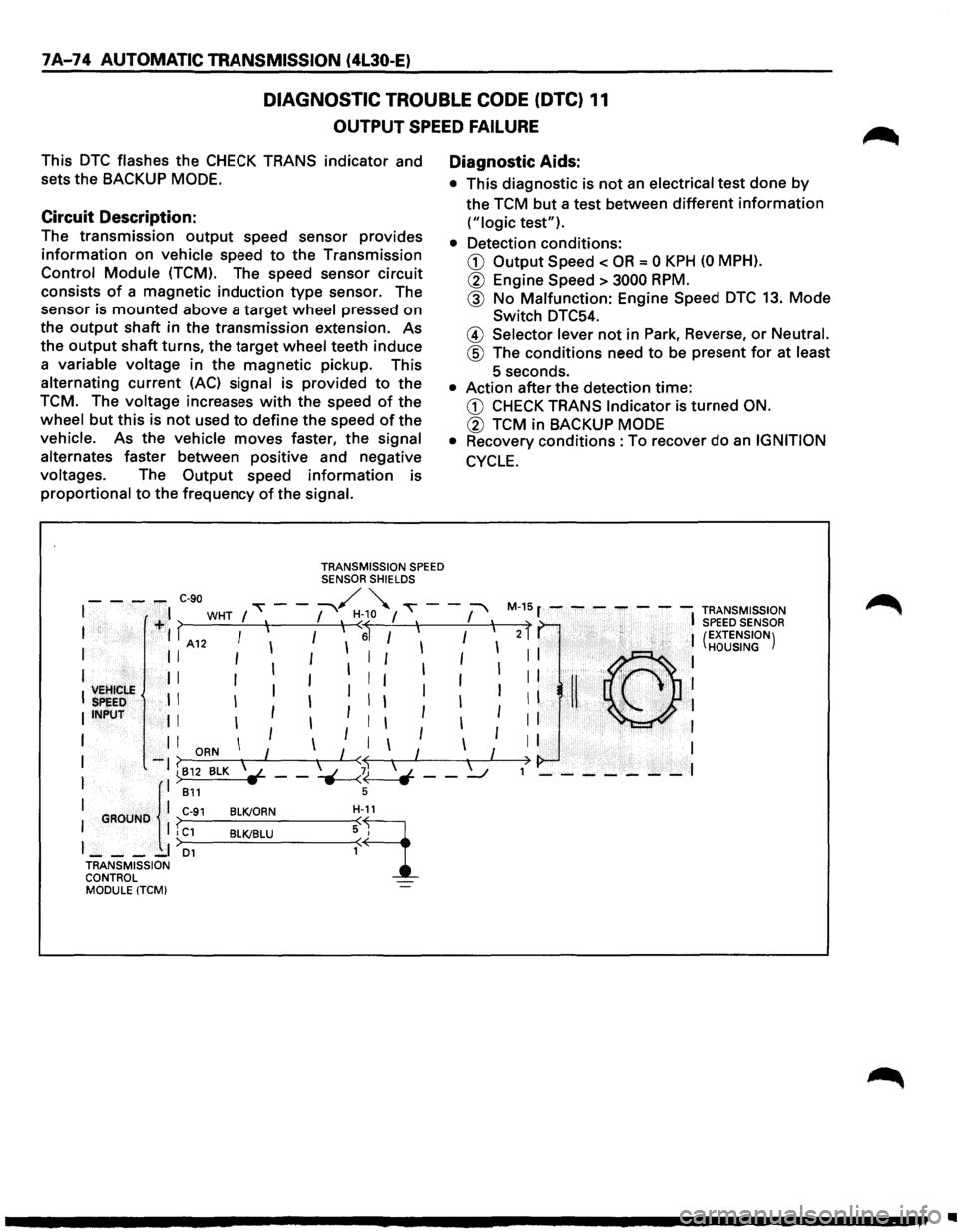
7 A-74 AUTOMATIC TRANSMISSION (4l30-E)
DIAGNOSTIC TROUBLE CODE (DTC) 11
OUTPUT SPEED FAILURE
This DTC flashes the CHECK TRANS indicator and
sets the
BACKUP MODE.
Circuit Description:
The transmission output speed sensor provides
information on vehicle speed to the Transmission
Control Module (TCM). The speed sensor circuit
consists
of a magnetic induction type sensor. The
sensor is
mounted above a target wheel pressed on
the
output shaft in the transmission extension. As
the
output shaft turns, the target wheel teeth induce
a variable voltage in the magnetic pickup. This
alternating current
(AC) signal is provided to the
TCM. The voltage increases with the speed of the
wheel
but this is not used to define the speed of the
vehicle. As the vehicle
moves faster, the signal
alternates faster between positive and negative
voltages. The
Output speed information is
proportional to the frequency of the signal.
TRANSMISSION SPEED SENSOR SHIELDS
Diagnostic Aids:
• This diagnostic is not an electrical test done by
the TCM but a test between different information
("logic test").
• Detection conditions:
CD Output Speed < OR = 0 KPH (0 MPH).
® Engine Speed > 3000 RPM.
@ No Malfunction: Engine Speed DTC 13. Mode
Switch DTC54.
@ Selector lever not in Park, Reverse, or Neutral.
@ The conditions need to be present for at least
5 seconds.
• Action after the detection time:
CD CHECK TRANS Indicator is turned ON.
® TCM in BACKUP MODE
•
Recovery conditions :To recover do an IGNITION
CYCLE.
- - -,.,.. C-90 "" - -~ ~ ""\' - -:-' M-15 r - - - - - - -TRANSMISSION I I WHT I , I , H<~o I , I , t , I SPEED SENSOR I +I > I I I I 6 I I I I 2 I (EXTENSION) I A12 I I I HOUSING
I II 111
11111111 ©I
', VEHICLE ', II I
I I I I I I I I I I !I ' ,~, 1
:
SPEED . I I I I I I I I I II "-.
I INPUT I I I I I I I I I I
I I I
ORN I I I I I I I I
I
-1 ~812 BLK l-- -~b - -~ ,> - - - - - - -I
I ll B11 s
I GROUND I C-91 BLK/ORN H-9_11
I I I C1 BLK/BLU : I
J __ -_I D1
TRANSMISSION
CONTROL MODULE
(TCM)
•
Page 950 of 1928
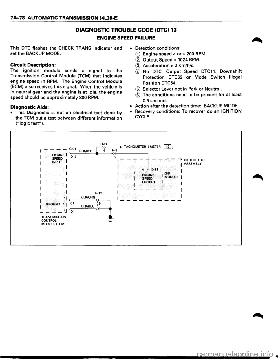
7A-78 AUTOMATIC TRANSMISSION (4L30-E)
DIAGNOSTIC TROUBLE CODE (DTC) 13
ENGINE SPEED FAILURE
This DTC flashes the CHECK TRANS indicator and
set the BACKUP
MODE.
Circuit Description:
The ignition module sends a signal to the
Transmission
Control Module (TCM) that indicates
engine speed in
RPM. The Engine Control Module
(ECM) also receives this signal. When the vehicle is
in
neutral gear and the engine is at idle, the engine
speed
should be approximately 800 RPM.
Diagnostic Aids:
• This Diagnostic is not an electrical test done by
the TCM but a test between different information
("logic test"). •
Detection
conditions:
CD Engine speed< or= 200 RPM.
@ Output Speed > 1024 RPM.
@ Acceleration > 2 Km/h/s.
@ No DTC: Output Speed DTC11, Downshift
Protection DTC62 or Mode Switch Illegal
Position DTC54.
@ Selector Lever not in Park or Neutral.
@ The conditions need to be present for at least
0.5
second.
• Action after the detection time: BACKUP MODE
•
Recovery conditions: To recover do an IGNITION
CYCLE
>--
-------t~lt--H--4~>-_4=.--+· TACHOMETER (METER [!1]31 r - - - -C-91 BLK/RED ~ H·S
I ENGINE I fD12 (A SPEED I I - - - - - - - --, DISTRIBUTOR I INPUT I I ASSEMBLy
I I I I 4 E-21 l I 1 r----ots 1 I I ENGINE I MODULE I
I II I I SPeED I OUTPUT 1
I II I ~---..J I
I I I H-11 I I
I GROUND {II fc1 BLK!ORN~q I_---------
I ) BLK/BLU ~ 1
'----j D1 TRANSMISSION CONTROL MODULE (TCMI
..