ECO mode ISUZU TROOPER 1995 Owner's Guide
[x] Cancel search | Manufacturer: ISUZU, Model Year: 1995, Model line: TROOPER, Model: ISUZU TROOPER 1995Pages: 1928
Page 952 of 1928
1 A-80 AUTOMATIC TRANSMISSION (4L30-E)
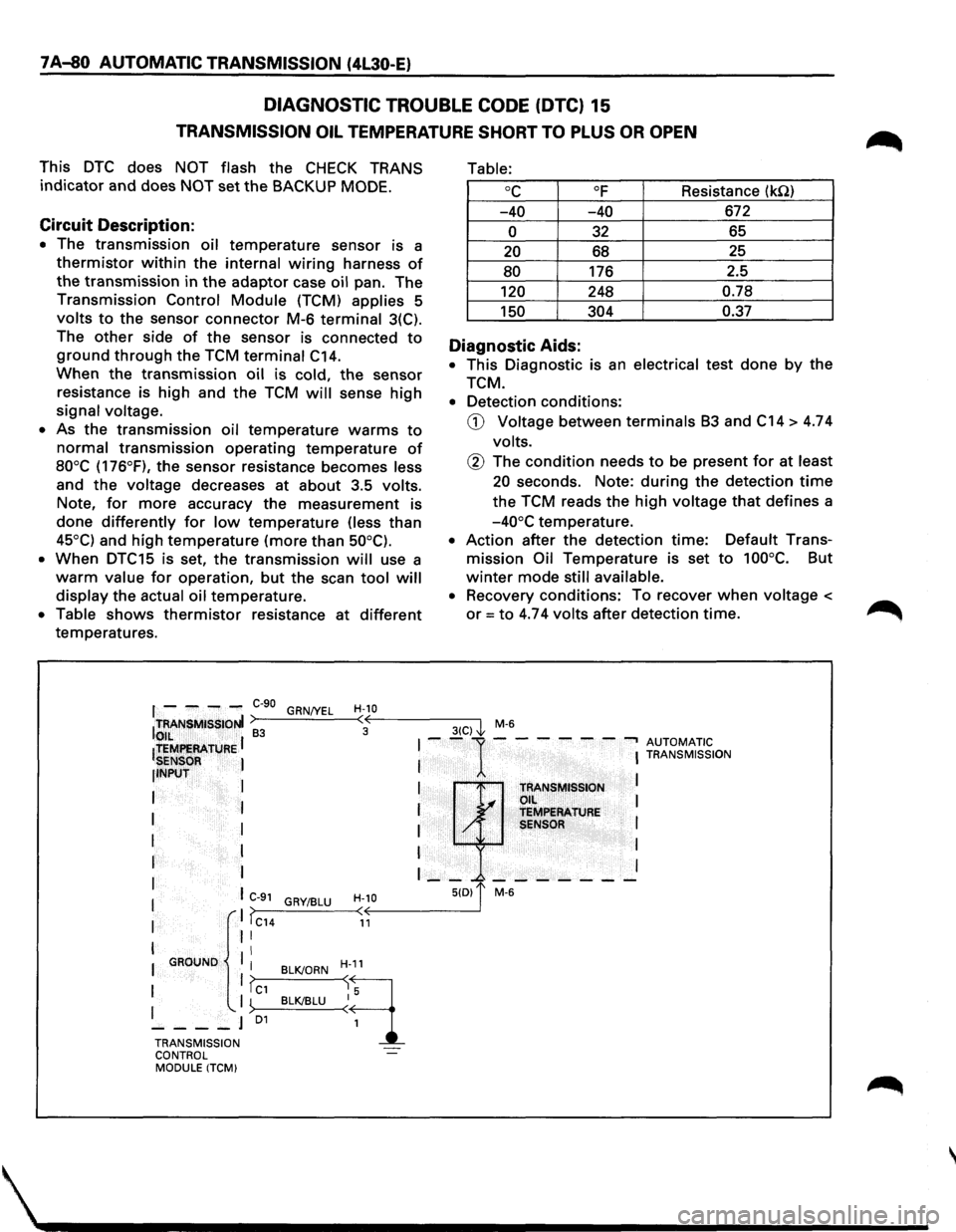
DIAGNOSTIC TROUBLE CODE (DTC) 15
TRANSMISSION OIL TEMPERATURE SHORT TO PLUS OR OPEN
This DTC does NOT flash the CHECK TRANS
indicator and does NOT set the BACKUP MODE.
Circuit Description:
• The transmission oil temperature sensor is a
thermistor within the internal wiring harness of
the transmission in the adaptor case oil pan. The
Transmission Control Module (TCM) applies 5
volts to the sensor connector M-6 terminal 3(C).
The
other side of the sensor is connected to
ground through the TCM terminal C14.
When the transmission oil is cold, the sensor
resistance is high and the TCM will sense high
signal voltage.
• As the transmission oil temperature warms to
normal transmission operating temperature of
80°C (176°F), the sensor resistance becomes less
and
the voltage decreases at about 3.5 volts.
Note,
for more accuracy the measurement is
done differently for low temperature (less than
45°C) and high temperature (more than 50°C).
•
When DTC15 is set, the transmission will use a
warm value for operation, but the scan tool will
display the actual oil temperature.
• Table shows thermistor resistance at different
temperatures.
Table:
oc OF Resistance (kQ)
-40 -40 672
0 32 65
20 68 25
80 176
2.5
120 248 0.78
150 304 0.37
Diagnostic Aids:
• This Diagnostic is an electrical test done by the
TCM.
• Detection conditions:
CD Voltage between terminals B3 and C14 > 4.74
volts.
@ The condition needs to be present for at least
20 seconds. Note: during the detection time
the TCM reads the high voltage that defines a
-40°C temperature.
• Action after the detection time: Default Trans
mission Oil Temperature is set to 100°C. But
winter mode still available.
• Recovery conditions: To recover when voltage <
or= to 4.74 volts after detection time.
f - ---C-90 GRN/YEL H-10 ITRANSMISSIONI >---'----<•((,--------3-(C--,) I M-6 to,,IL ~ 3 ~
ltEMf!EAATURE I I --1---- ---, AUTOMATIC
SENSOR I I I TRANSMISSION
llNPUT
I
I I
I TRANSMISSION L.... Oil I
I I I ~ TEMPERATURE
I I I / SENSOR I
I I I I
r I I __ _. _______ I
I I C-91 H-10 5(0) 1' M-6 GRY/BLU I ,. I >>---_:__--< < I IC14 11
I II
II I GROUND
I BLK/ORN H-11
1 1?c1 ~q I '-. I ~>--B_L__cKI_BL_U--<~ 5
----J 01
1
TRANSMISSION
CONTROL
MODULE ITCM)
Page 954 of 1928
7 A-82 AUTOMATIC TRANSMISSION (4L30-E)
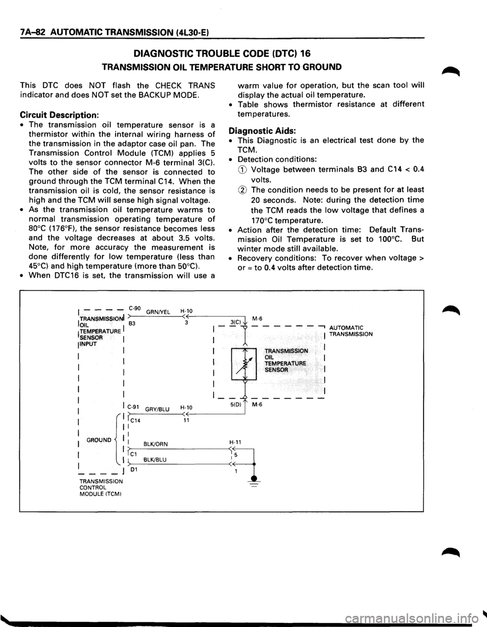
DIAGNOSTIC TROUBLE CODE (DTC) 16
TRANSMISSION OIL TEMPERATURE SHORT TO GROUND
This DTC does NOT flash the CHECK TRANS
indicator and does NOT set the BACKUP MODE.
Circuit Description:
• The transmission oil temperature sensor is a
thermistor within the internal wiring harness of
the transmission in the adaptor case oil pan. The
Transmission Control Module (TCM) applies 5
volts to the sensor connector M-6 terminal 3(C).
The
other side of the sensor is connected to
ground through the TCM terminal C14. When the
transmission oil is cold, the sensor resistance is
high and the TCM will sense high signal voltage.
•
As the transmission oil temperature warms to
normal transmission operating temperature of
aooc (176°F), the sensor resistance becomes less
and the voltage decreases at about 3.5 volts.
Note, for more accuracy the measurement is
done differently for low temperature (less than
45°C) and high temperature (more than 50°C).
•
When DTC16 is set, the transmission will use a
warm value for operation, but the scan tool will
display the actual oil temperature.
• Table shows thermistor resistance at different
temperatures.
Diagnostic Aids:
• This Diagnostic is an electrical test done by the
TCM.
• Detection conditions:
G) Voltage between terminals B3 and C14 < 0.4
volts.
@ The condition needs to be present for at least
20 seconds. Note: during the detection time
the TCM reads the low voltage that defines a
170°C temperature.
• Action after the detection time: Default Trans
mission Oil Temperature is set to 100°C. But
winter mode still available.
•
Recovery conditions: To recover when voltage >
or = to 0.4 volts after detection time.
I - - - -e-go GRN/YEL H-10
ITRANSMISSIONI >----'-----<:·oE---------3-(C-)-,'1 M-6
OIL I 83 I--1-- --- -.., AUTOMATIC !TEMPERATURE I I TRANSMISSION SENSOR NPUT I TRANSMISSION I .I OIL I I y TEMPERATURE I / SENSOR I
I
I I
I __ _.-------
C>--9_1_G_RY_I_BL_U_-
TRANSMISSION ~·· ... -l
CONTROL MODULE !TCM)
Page 956 of 1928
7 A-84 AUTOMATIC TRANSMISSION (4L30-E)
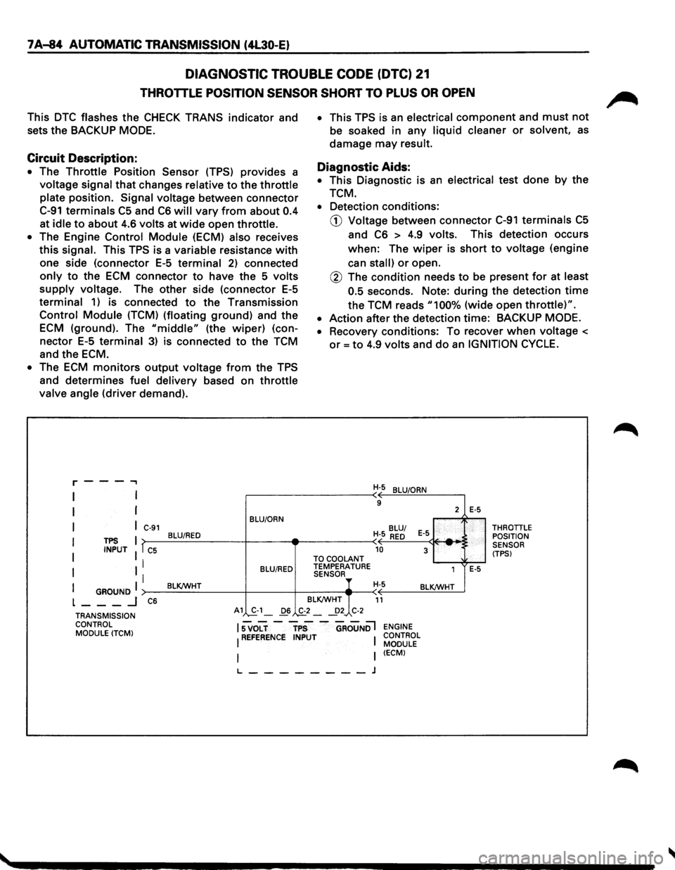
DIAGNOSTIC TROUBLE CODE (DTC) 21
THROTTLE POSITION SENSOR SHORT TO PLUS OR OPEN
This DTC flashes the CHECK TRANS indicator and
sets
the BACKUP MODE.
Circuit Description:
• The Throttle Position Sensor (TPS) provides a
voltage signal that changes relative to the throttle
plate position. Signal voltage between connector
C-91 terminals C5 and C6 will vary from about 0.4
at idle to about 4.6 volts at wide open throttle.
• The Engine Control Module (ECM) also receives
this signal. This TPS is a variable resistance with
one side (connector E-5 terminal 2) connected
only to the ECM connector to have the 5 volts
supply voltage. The other side (connector E-5
terminal 1) is connected to the Transmission
Control Module (TCM) (floating ground) and the
ECM (ground). The "middle" (the wiper) (con
nector E-5 terminal 3) is connected to the TCM
and
the ECM.
• The ECM monitors output voltage from the TPS
and determines fuel delivery based on throttle
valve angle (driver demand).
r---...,
I
I
I
I
I
I
TPS INPUT
I GROUND I L ___ _j
C-91
T C5
I
I
C6
BLU/ORN
BLU/RED
BLU/RED
BLK/WHT
• This TPS is an electrical component and must not
be soaked in any liquid cleaner or solvent, as
damage may result.
Diagnostic Aids:
• This Diagnostic is an electrical test done by the
TCM.
• Detection conditions:
CD Voltage between connector C-91 terminals C5
and C6 > 4.9 volts. This detection occurs
when: The wiper is short to voltage (engine
can
stall) or open.
@ The condition needs to be present for at least
0.5
seconds. Note: during the detection time
the TCM reads "100% (wide open throttle)".
• Action after the detection time: BACKUP MODE.
•
Recovery conditions: To recover when voltage <
or= to 4.9 volts and do an IGNITION CYCLE.
H-5 BLU/ORN
9
BLU/
H-5
RED E-5
-10 3 TO COOLANT TEMPERATURE
1 SENSOR H-5 BLK/WHT
BLK/WHT
11
2 E-5
E-5
THROTTLE POSITION
SENSOR
(TPS)
TRANSMISSION CONTROL MODULE
(TCM)
A1 S.-1_ 06 .,&_2 _ _!>2 C-2
lsvoLT-rps -aRouNDl ENGINE
I REFERENCE INPUT I CONTROL MODULE
I (ECM)
L--------J
Page 958 of 1928
7A-86 AUTOMATIC TRANSMISSION (4L30-E)
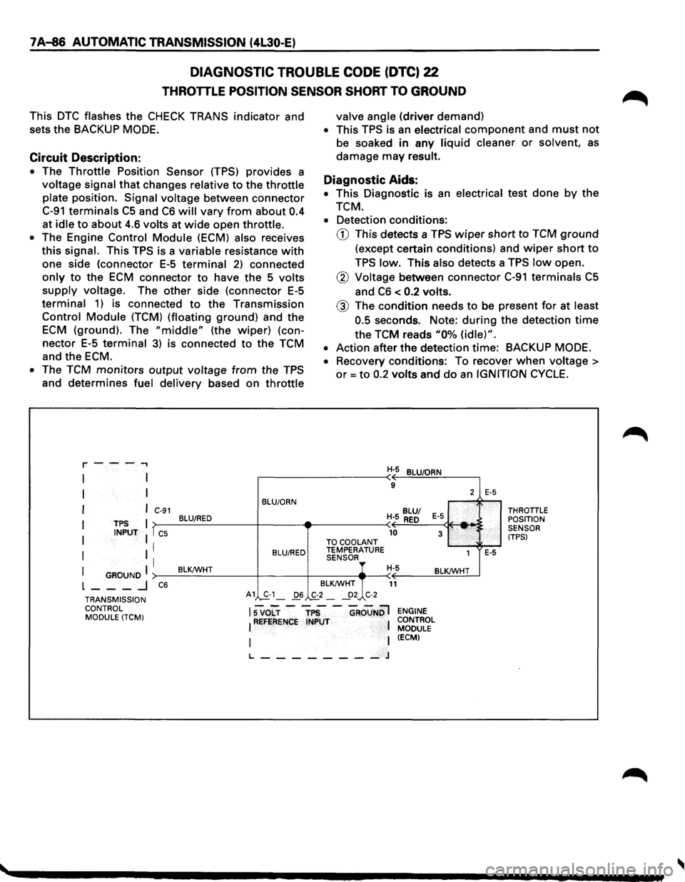
DIAGNOSTIC TROUBLE CODE (DTC) 22
THROTTLE POSITION SENSOR SHORT TO GROUND
This DTC flashes the CHECK TRANS indicator and
sets
the BACKUP MODE.
Circuit Description:
• The Throttle Position Sensor (TPS) provides a
voltage signal that changes relative to the throttle
plate position. Signal voltage between connector
C-91 terminals C5 and C6 will vary from about 0.4
at idle to about 4.6 volts at wide open throttle.
• The Engine Control Module (ECM) also receives
this signal. This TPS is a variable resistance with
one side (connector E-5 terminal 2) connected
only to the ECM connector to have the 5 volts
supply voltage. The other side (connector E-5
terminal 1) is connected to the Transmission
Control Module (TCM) (floating ground) and the
ECM (ground). The "middle" (the wiper) (con
nector E-5 terminal 3) is connected to the TCM
and the ECM.
• The TCM monitors output voltage from the TPS
and determines fuel delivery based on throttle
r---.,
I
I
I
I
I
I
TPS INPUT
I GROUND I L ___ .J
C-91
T C5
I
I
C6
BLU/ORN
BLU/RED
BLU/RED
BLK!WHT
valve angle (driver demand)
• This TPS is an electrical component and must not
be soaked in any liquid cleaner or solvent, as
damage may result.
Diagnostic Aids:
• This Diagnostic is an electrical test done by the
TCM.
• Detection conditions:
G) This detects a TPS wiper short to TCM ground
(except certain conditions) and wiper short to
TPS low. This also detects a TPS low open.
® Voltage between connector C-91 terminals C5
and C6 < 0.2 volts.
@ The condition needs to be present for at least
0.5
seconds. Note: during the detection time
the TCM reads "0% (idle)".
• Action after the detection time: BACKUP MODE.
•
Recovery conditions: To recover when voltage >
or= to 0.2 volts and do an IGNITION CYCLE.
H-5 BLU/ORN
9
BLU/
H- 5 RED E-5 _. 10 3 TO
COOLANT TEMPERATURE
1 SENSOR, H-5 BLK!WHT
BLK!WHT
11
2
:
E-5
E-5
THROTTLE POSITION
SENSOR
(TPS)
TRANSMISSION CONTROL MODULE
(TCM)
A1 S-1_ D6 ._£2-~2_, C-2
lsvo"Lr -"TP5 -"GRouNDl !REFERENCE INPUT 1
I I t_ ________ J
ENGINE
CONTROL MODULE
(ECM)
Page 960 of 1928
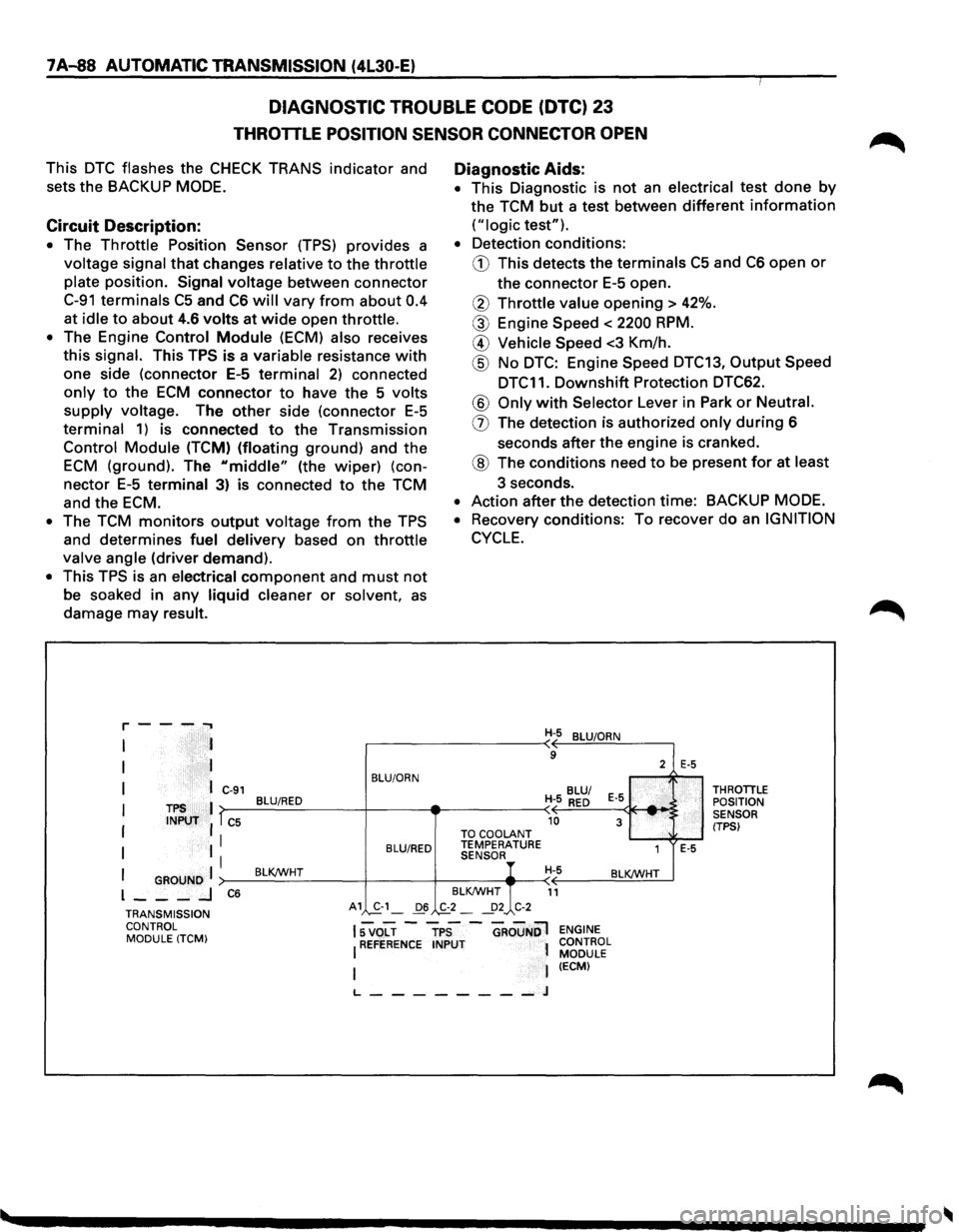
7A-88 AUTOMATIC TRANSMISSION (4l30-E)
DIAGNOSTIC TROUBLE CODE (DTC) 23
THROTTLE POSITION SENSOR CONNECTOR OPEN
This DTC flashes the CHECK TRANS indicator and
sets
the BACKUP MODE.
Circuit Description:
• The Throttle Position Sensor (TPS) provides a
voltage signal that changes relative to the throttle
plate position. Signal voltage between connector
C-91 terminals C5 and C6 will vary from about 0.4
at
idle to about 4.6 volts at wide open throttle.
• The Engine Control Module (ECM) also receives
this signal. This TPS is a variable resistance with
one side (connector E-5 terminal 2) connected
only to the ECM connector to have the 5 volts
supply voltage. The other side (connector E-5
terminal 1) is connected to the Transmission
Control Module (TCM) (floating ground) and the
ECM (ground). The "middle" (the wiper) (con
nector E-5 terminal 3) is connected to the TCM
and
the ECM.
• The TCM monitors output voltage from the TPS
and
determines fuel delivery based on throttle
valve angle (driver demand).
• This TPS is an electrical component and must not
be soaked in any liquid cleaner or solvent, as
damage may result.
r--...... ..,
I
I
I
TPS INPUT
I GROUND I l ___ _J
C-91
l C5
I
I
C6
BLU/ORN
BLU/RED
BLU/RED
BLKJWHT
A1 ,S.-1_ 06
Diagnostic Aids:
• This Diagnostic is not an electrical test done by
the TCM but a test between different information
("logic test").
• Detection conditions:
G) This detects the terminals C5 and C6 open or
the connector E-5 open.
® Throttle value opening > 42%.
® Engine Speed < 2200 RPM.
@ Vehicle Speed <3 Km/h.
@ No DTC: Engine Speed DTC13, Output Speed
DTC11.
Downshift Protection DTC62.
® Only with Selector Lever in Park or Neutral.
(]) The detection is authorized only during 6
seconds
after the engine is cranked.
® The conditions need to be present for at least
3 seconds.
• Action after the detection time: BACKUP MODE.
• Recovery conditions: To recover do an IGNITION
CYCLE.
TO COOLANT TEMPERATURE SENSOR
BLKJWHT
.,£2_ ~2 C-2
H-5 BLUIORN
9
2
BLU/
H- 5
RED E-5
10 3 .... ,'
1
H-5 BLKJWHT
11
E-5
E-5
THROTILE
POSITION
SENSOR
(TPSI
TRANSMISSION CONTROL MODULE (TCM)
15 VOLT -TPS -GROuNOl ENGINE
I REFERENCE INPUT 1 CONTROL l MODULE I (ECM)
L--------J
Page 962 of 1928
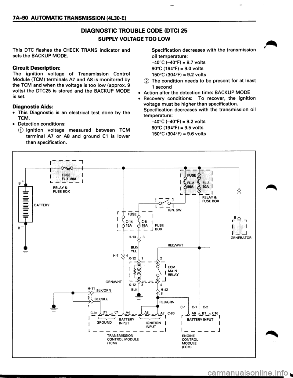
7 A-90 AUTOMATIC TRANSMISSION (4L30-E)
DIAGNOSTIC TROUBLE CODE (DTC) 25
SUPPLY VOLTAGE TOO LOW
This DTC flashes the CHECK TRANS indicator and
sets the BACKUP
MODE.
Specification decreases with the transmission
oil temperature:
Circuit Description:
-40°C (-40°F) = S.7 volts
90°C (194°F) = 9.0 volts
150°C (304°F) = 9.2 volts The ignition voltage of Transmission Control
Module (TCM) terminals A7 and AS is monitored by
the TCM and when the voltage is too low (approx. 9
volts) the DTC25 is stored and the BACKUP MODE
is set.
@ The condition needs to be present for at least
1 second
• Action after the detection time: BACKUP MODE
Diagnostic Aids:
• This Diagnostic is an electrical test done by the
TCM.
• Recovery conditions: To recover, the ignition
voltage must be higher than specification.
Specification decreases
with the transmission oil
temperature:
-40°C (-40°F) = 9.2 volts
90°C (194°F) = 9.5 volts
150°C (304°F) = 9.6 volts
• Detection conditions:
CD Ignition voltage measured between TCM
terminal A7 or AS and ground C1 is lower
than specification .
. · fU I
I '
f:L;~soA L., ____ J
RELAY & FUSE BOX
1--, {)-:,.--____..J BATTERY
l
T
L __ I
r
I C-14 C-8 I I 15A 15A FUSE -__ + _ j BOX
H-13t 3
H-7 'x~.~~'---7 r ]_-
GRN/WHT
BATTERY I GROUND INPUT IGNITION I INPUT I
L-----------TRANSMISSION
CONTROL MODULE
(TCM) IGN.SW.
RED/WHT
C-1 C-1 C-2
A6 B1 C16
r -;ATTERV INPUT-l
I
I l _____ j
ENGINE
CONTROL MODULE
(ECM)
I I
I-_j GENERATOR
Page 964 of 1928
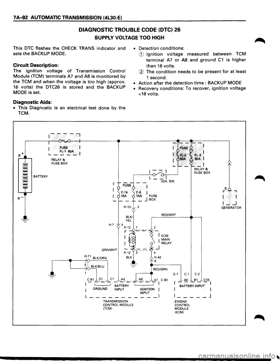
7 A-92 AUTOMATIC TRANSMISSION (4L30-E)
DIAGNOSTIC TROUBLE CODE (DTC) 26
SUPPLY VOLTAGE TOO HIGH
This DTC flashes the CHECK TRANS indicator and
sets the
BACKUP MODE.
Circuit Description:
The ignition voltage of Transmission Control
Module (TCM) terminals A7 and AS is monitored by
the TCM and when the voltage is too high (approx.
16 volts) the
DTC26 is stored and the BACKUP
MODE is set.
Diagnostic Aids:
• This Diagnostic is an electrical test done by the
TCM.
BATTERY
I FUSE I
L..-FL·1~A-I
RELAY & FUSE BOX
r
I
I
H-7
GRN/WHT
H-11 BLK/ORN
• Detection conditions:
CD Ignition voltage measured between TCM
terminal
A7 or AS and ground C1 is higher
than 16 volts.
® The condition needs to be present for at least
1 second.
• Action after the detection time : BACKUP MODE
• Recovery conditions: To recover, ignition voltage
<16
volts.
-F~;K--:
Fl:.-2 F•. L·3 50A 3DA 1
-_I
1--1 (1-,,--...----J L __ I
IGN.SW.
C-8 I 15A FUSE _ j BOX
3
RED/WHT
RELAY & FUSE BOX
r 1
I-..J GENERATOR
1
,-----------e-T ~:>( BLK/BLU
~ I RED/GRN
1
C-91 ~p:!_ C1 !-~ _ _ ~8-_ A7 C-90
C-1 C-1 C-2
I - - - -BATTER~ - - - -I
I GROUND INPUT IGNITION I INPUT l ___________ l
TRANSMISSION
CONTROL MODULE
(TCM)
_ A6 _B1_ C16
r BATTERY INPUT I I I
l _____ j
ENGINE
CONTROL
MODULE (ECM)
Page 966 of 1928
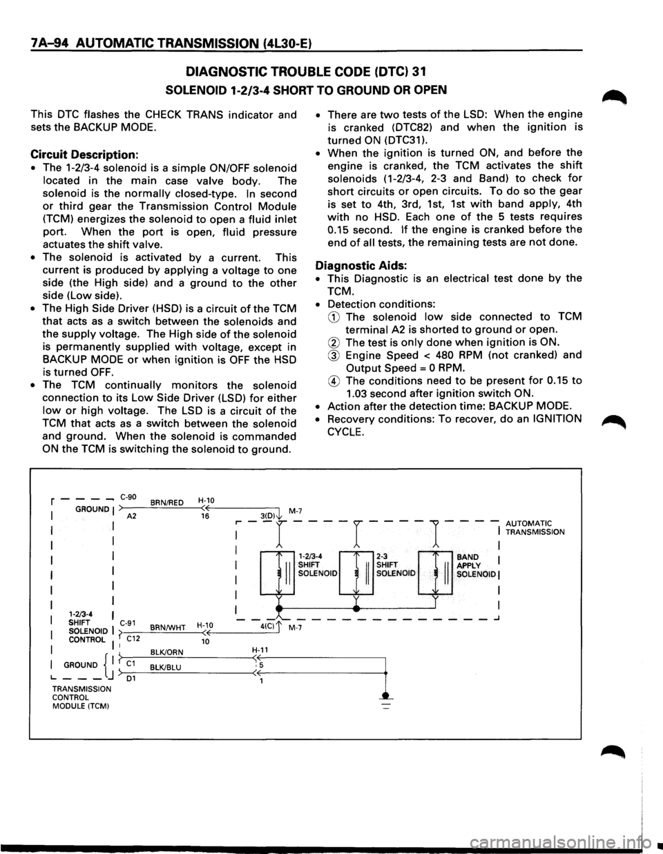
7 A-94 AUTOMATIC TRANSMISSION (4l30-E)
DIAGNOSTIC TROUBLE CODE (DTC) 31
SOLENOID 1-2/3-4 SHORT TO GROUND OR OPEN
This DTC flashes the CHECK TRANS indicator and
sets
the BACKUP MODE.
Circuit Description:
• The 1-2/3-4 solenoid is a simple ON/OFF solenoid
located
in the main case valve body. The
solenoid is the normally closed-type. In second
or third gear the Transmission Control Module
(TCM) energizes the solenoid to open a fluid inlet
port. When the port is open, fluid pressure
actuates the
shift valve.
•
The solenoid is activated by a current. This
current is produced by applying a voltage to one
side (the High side) and a
ground to the other
side (Low side).
• The High Side Driver (HSD) is a circuit of the TCM
that acts as a switch between the solenoids and
the
supply voltage. The High side of the solenoid
is permanently supplied with voltage, except in
BACKUP
MODE or when ignition is OFF the HSD
is turned OFF.
• The TCM continually monitors the solenoid
connection to its Low Side Driver (LSD) for either
low or high voltage. The LSD is a circuit of the
TCM that acts as a switch between the solenoid
and ground. When the solenoid is commanded
ON the TCM is switching the solenoid to ground.
r----C-90 BRN/RED H-10
• There are two tests of the LSD: When the engine
is cranked (DTC82) and when the ignition is
turned ON (DTC31 ).
• When the ignition is turned ON, and before the
engine is cranked, the TCM activates the shift
solenoids (1-2/3-4, 2-3 and Band) to check for
short circuits or open circuits. To do so the gear
is set
to 4th, 3rd, 1st, 1st with band apply, 4th
with no HSD. Each one of the 5 tests requires
0.15 second. If the engine is cranked before the
end of all tests, the remaining tests are not done.
Diagnostic Aids:
• This Diagnostic is an electrical test done by the
TCM.
• Detection conditions:
CD The solenoid low side connected to TCM
terminal A2 is shorted to ground or open.
® The test is only done when ignition is ON.
® Engine Speed < 480 RPM (not cranked) and
Output Speed = 0 RPM.
@ The conditions need to be present for 0.15 to
1.03 second after ignition switch ON.
•
Action after the detection time: BACKUP MODE.
•
Recovery conditions: To recover, do an IGNITION
CYCLE.
I GROUND I A2 3(D)j,. M-7 ( 16
I I
I I
I I
I
I
I
I 1·2/3·4
SHIFT C-91
I SOLENOID I j> BRN/WHT
I
CONTROL I I C12
I GROUND { I ? C1
BLK/ORN
J ) BLK/BLU
L..---D1 TRANSMISSION
CONTROL MODULE
(TCM)
H-10 ( 10
~ --r ----r ----1----~ ~~~~~~~~ION
I I
1m4 rnH SHIFT SHIFT II SOLENOID II SOLENOID
-y
-_........_ __________
--41Clf M-7
II
SAND I APPLY SOLENOID I
I
I
---.J
•
Page 968 of 1928
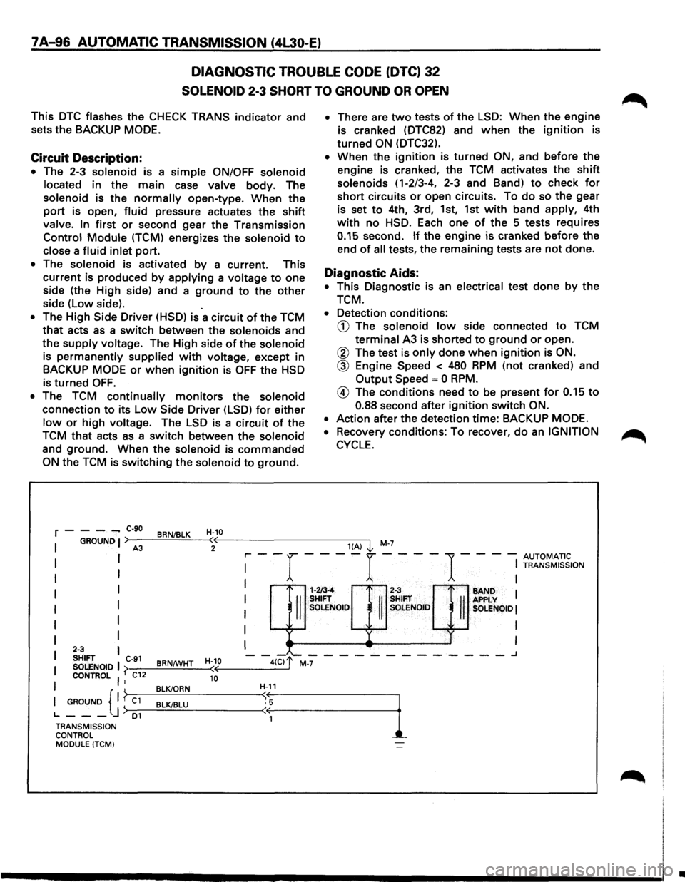
7 A-96 AUTOMATIC TRANSMISSION (4l30-E)
DIAGNOSTIC TROUBLE CODE (DTC) 32
SOLENOID 2-3 SHORT TO GROUND OR OPEN
This DTC flashes the CHECK TRANS indicator and
sets
the BACKUP MODE.
Circuit Description:
• The 2-3 solenoid is a simple ON/OFF solenoid
located in the main case valve body. The
solenoid is the normally open-type. When the
port is open, fluid pressure actuates the shift
valve. In first or second gear the Transmission
Control Module (TCM) energizes the solenoid to
close a fluid inlet port.
• The solenoid is activated by a current. This
current is produced by applying a voltage to one
side (the High side) and a ground to the other
side (Low side). .
• The High Side Driver (HSD) is a circuit of the TCM
that acts as a switch between the solenoids and
the supply voltage. The High side of the solenoid
is permanently supplied with voltage, except in
BACKUP
MODE or when ignition is OFF the HSD
is
turned OFF.
•
The TCM continually monitors the solenoid
connection to its Low Side Driver (LSD) for either
low or high voltage. The LSD is a circuit of the
TCM that acts as a switch between the solenoid
and ground. When the solenoid is commanded
ON the TCM is switching the solenoid to ground.
r---_ c-9o
BRN/BLK H-10
I GROUNDJ) (( A3 2
• There are two tests of the LSD: When the engine
is cranked (DTC82) and when the ignition is
turned ON (DTC32).
• When the ignition is turned ON, and before the
engine is cranked, the TCM activates the shift
solenoids (1-2/3-4, 2-3 and Band) to check for
short circuits or open circuits. To do so the gear
is set to 4th, 3rd, 1st, 1st with band apply, 4th
with no HSD. Each one of the 5 tests requires
0.15 second. If the engine is cranked before the
end of all tests, the remaining tests are not done.
Diagnostic Aids:
• This Diagnostic is an electrical test done by the
TCM.
• Detection conditions:
CD The solenoid low side connected to TCM
terminal A3 is shorted to ground or open.
@ The test is only done when ignition is ON.
@ Engine Speed < 480 RPM (not cranked) and
Output Speed = 0 RPM.
@ The conditions need to be present for 0.15 to
0.88 second after ignition switch ON.
•
Action after the detection time: BACKUP MODE.
•
Recovery conditions: To recover, do an IGNITION
CYCLE.
1(A) '1 M-7
,.... --r ----r ----
1 - -- -
AUTOMATIC I
I TRANSMISSION
I I
I I
I I
I BAND I APPLY I SOLENOID!
I
I
I I
I
I
I
I
I I
I I
I 2·3 I SHIFT C-91 H-10
I SOLENOID I
( BRN/WHT (
I
CONTROl I I C12 10
I GROUND { I ? C1
BLK/ORN
j) BLK/BLU L.---D1
1-2/3-4 2-3
II
SHIFT
II
SHIFT
II SOLENOID SOLENOID
-"--------------..J
TRANSMISSION
CONTROL
MODULE (TCM)
•
Page 970 of 1928
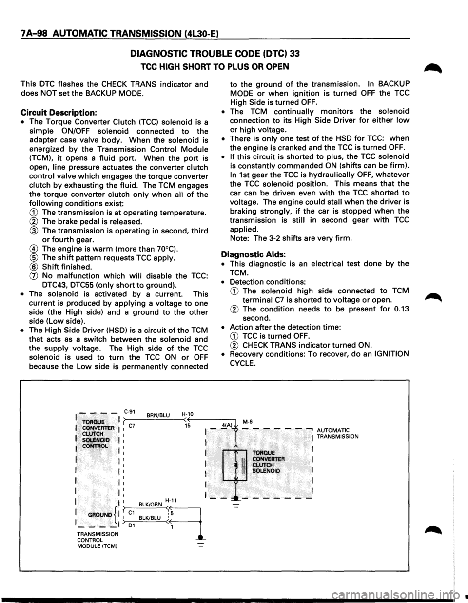
7 A-98 AUTOMATIC TRANSMISSION (4L30-E)
DIAGNOSTIC TROUBLE CODE (DTC) 33
TCC HIGH SHORT TO PLUS OR OPEN
This DTC flashes the CHECK TRANS indicator and
does NOT set the BACKUP MODE.
Circuit Description:
• The Torque Converter Clutch (TCC) solenoid is a
simple ON/OFF solenoid connected to the
adapter case valve body. When the solenoid is
energized
by the Transmission Control Module
(TCM), it opens a fluid port. When the port is
open,
line pressure actuates the converter clutch
control valve which engages the torque converter
clutch by exhausting the fluid. The TCM engages
the torque converter clutch only when all of the
following conditions exist:
G) The transmission is at operating temperature.
® The brake pedal is released.
® The transmission is operating in second, third
or fourth gear.
@ The engine is warm (more than 70°C).
® The shift pattern requests TCC apply.
® Shift finished.
(]) No malfunction which will disable the TCC:
DTC43, DTC55
(only short to ground).
• The solenoid is activated by a current. This
current is produced by applying a voltage to one
side (the High side) and a ground to the other
side (low side).
• The High Side Driver (HSD) is a circuit of the TCM
that acts as a switch between the solenoid and
the supply voltage. The High side of the TCC
solenoid is used to turn the TCC ON or OFF
because the Low side is permanently connected
to the ground of the transmission. In BACKUP
MODE
or when ignition is turned OFF the TCC
High Side is
turned OFF.
• The TCM continually monitors the solenoid
connection to its High Side Driver for either low
or high voltage.
• There is only one test of the HSD for TCC: when
the engine is cranked and the TCC is turned OFF.
•
If this circuit is shorted to plus, the TCC solenoid
is constantly commanded ON (shifts can be firm).
In 1st gear the TCC is hydraulically OFF, whatever
the TCC solenoid position. This means that the
car can be driven even with the TCC shorted to
voltage. The engine could stall when the driver is
braking strongly, if the car is stopped when the
transmission is still in second gear with TCC
applied. Note: The 3-2
shifts are very firm.
Diagnostic Aids:
• This diagnostic is an electrical test done by the
TCM.
• Detection conditions:
G) The solenoid high side connected to TCM
terminal C7 is shorted to voltage or open.
® The condition needs to be present for 0.13
second.
• Action after the detection time:
G) TCC is turned OFF.
® CHECK TRANS indicator turned ON.
•
Recovery conditions: To recover, do an IGNITION
CYCLE.
I - - - -C-91 BRN/BLU H-10
TOFlQU!;
I ? (( 4(A) J., M-6
I Cot!M:R'teR I I c7 15 I --1· -.-- - - ---. AUTOMATIC .. CLU'IrlilH I I S~NOib I I I TRANSMISSION
leoti~~~~ I . I I T()ftotJE
I I I I II CoHVEMER I I ' CLUTCH I I I I SQLENOID I
I 1: I I
I II I I I
I I H-11 - --!._-- - - - - -
{ I
{
BLK/ORN ~
9
-=-
1 GROUND I I C1 BLK/BLU : 5
1_--_,) 01 ( 1
TRANSMISSION
CONTROL MODULE (TCM)
•