10-30 BODY
CROSS BEAM ASSEMBLY
2 6
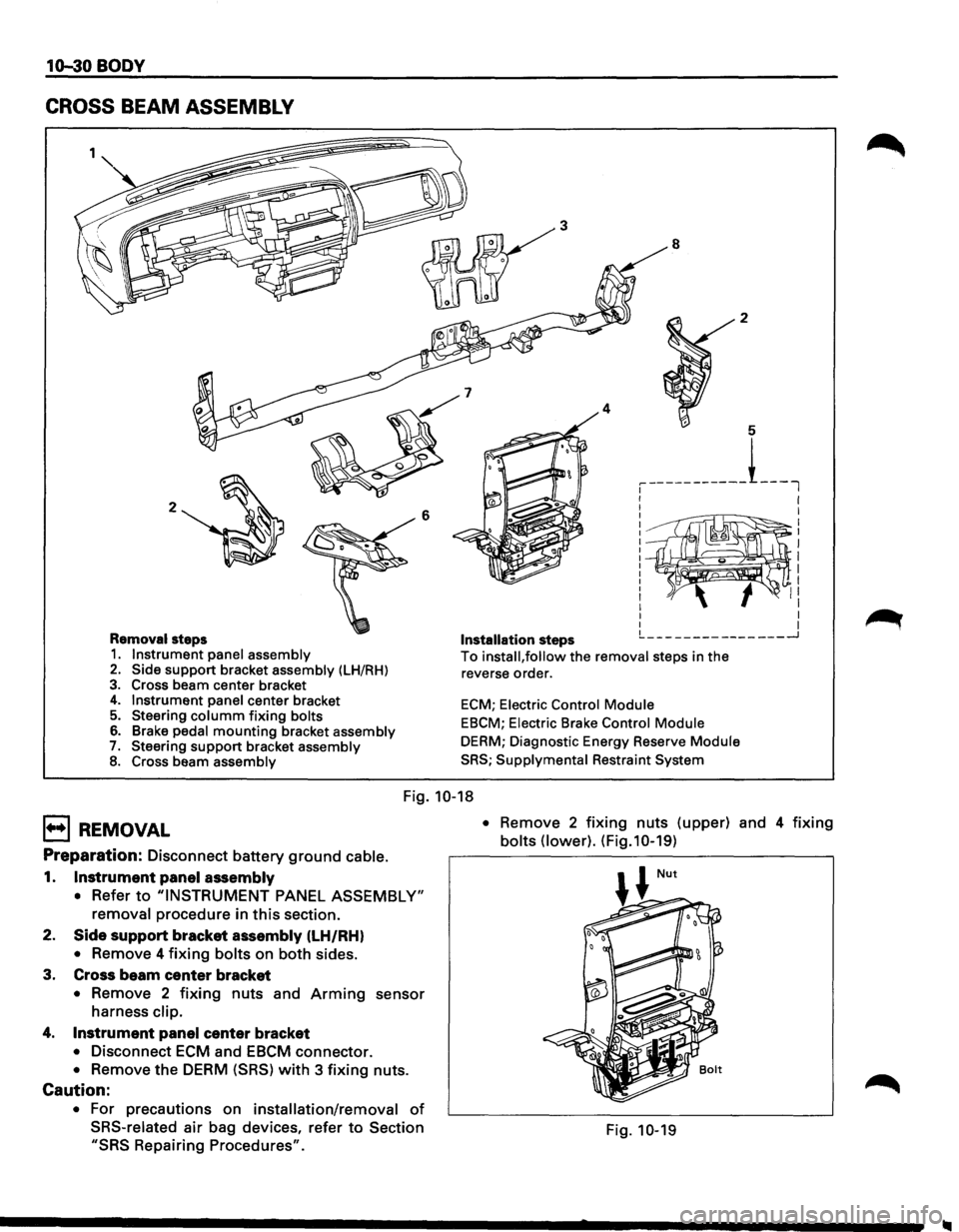
Removal steps 1. Instrument panel assembly 2. Side support bracket assembly (LH/RH)
3. Cross beam center bracket 4. Instrument panel center bracket 5. Steering columm fixing bolts
6. Brake pedal mounting bracket assembly 7. Steering support bracket assembly 8. Cross beam assembly
3
4
Installation steps
8 2
5
, -----------L_l
I I
I
I I
~~~~~®~! II I I I I !._ ___ ---------___ _J
To install, follow the removal steps in the
reverse order.
ECM; Electric Control Module
EBCM; Electric Brake Control Module
DERM; Diagnostic Energy Reserve Module
SRS; Supplymental Restraint System
Fig. 10-18
E) REMOVAL
Preparation: Disconnect battery ground cable.
1. Instrument panel assembly
• Refer to "INSTRUMENT PANEL ASSEMBLY"
removal procedure in this section.
2.
Side support bracket assembly (LH/RH)
• Remove 4 fixing bolts on both sides.
3. Cross beam
center bracket
• Remove 2 fixing nuts and Arming sensor
harness clip.
4. Instrument panel center bracket
• Disconnect ECM and EBCM connector.
• Remove the DERM (SRS) with 3 fixing nuts.
Caution:
• For precautions on installation/removal of
SRS-related air bag devices, refer to Section
"SRS Repairing Procedures". •
Remove
2 fixing nuts (upper) and 4 fixing
bolts (lower). (Fig.10-19)
Fig. 10-19
SUN ROOF DRAIN HOSE
FRONT SIDE
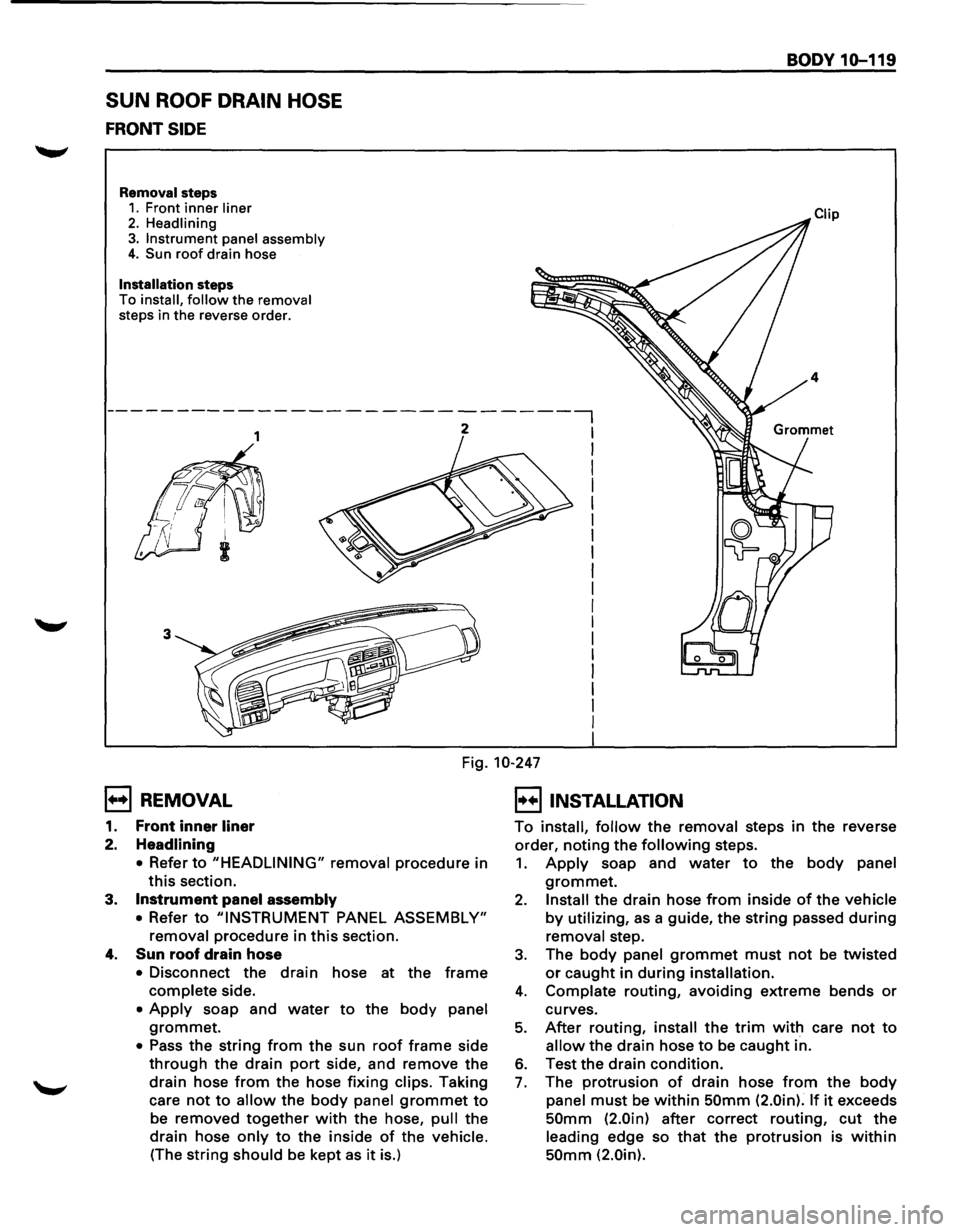
Removal steps 1. Front inner liner
2. Headlining 3. Instrument panel assembly 4. Sun roof drain hose
Installation steps
To install, follow the removal steps in the reverse order.
BODY 10-119
Fig. 10-247
B REMOVAL
1. Front inner liner
2. Headlining
• Refer to "HEADLINING" removal procedure in
this section.
3. Instrument panel assembly
• Refer to "INSTRUMENT PANEL ASSEMBLY"
removal procedure in this section.
4. Sun roof drain hose
• Disconnect the drain hose at the frame
complete side.
• Apply soap and water to the body panel
grommet.
• Pass the string from the sun roof frame side
through the drain port side, and remove the
drain hose from the hose fixing clips. Taking
care
not to allow the body panel grommet to
be removed together with the hose, pull the
drain hose only to the inside of the vehicle.
(The string
should be kept as it is.)
B INSTALLATION
To install, follow the removal steps in the reverse
order,
noting the following steps.
1. Apply soap and water to the body panel
grommet.
2. Install the drain hose from inside of the vehicle
by utilizing, as a guide, the string passed during
removal step.
3. The body panel grommet must not be twisted
or caught in during installation.
4. Complate routing, avoiding extreme bends or
curves.
5. After routing, install the trim with care not to
allow the drain hose to be caught in.
6. Test the drain condition.
7. The protrusion of drain hose from the body
panel must be within 50mm (2.0in). If it exceeds
50mm (2.0in) after correct routing, cut the
leading edge so that the protrusion is within
50mm (2.0in).