instrument panel ISUZU TROOPER 1995 Service Manual
[x] Cancel search | Manufacturer: ISUZU, Model Year: 1995, Model line: TROOPER, Model: ISUZU TROOPER 1995Pages: 1928
Page 1441 of 1928
AUDIO
AUTO ANTENNA
Refer to Section 9A "RADIO" for details.
CIGARETTE LIGHTER
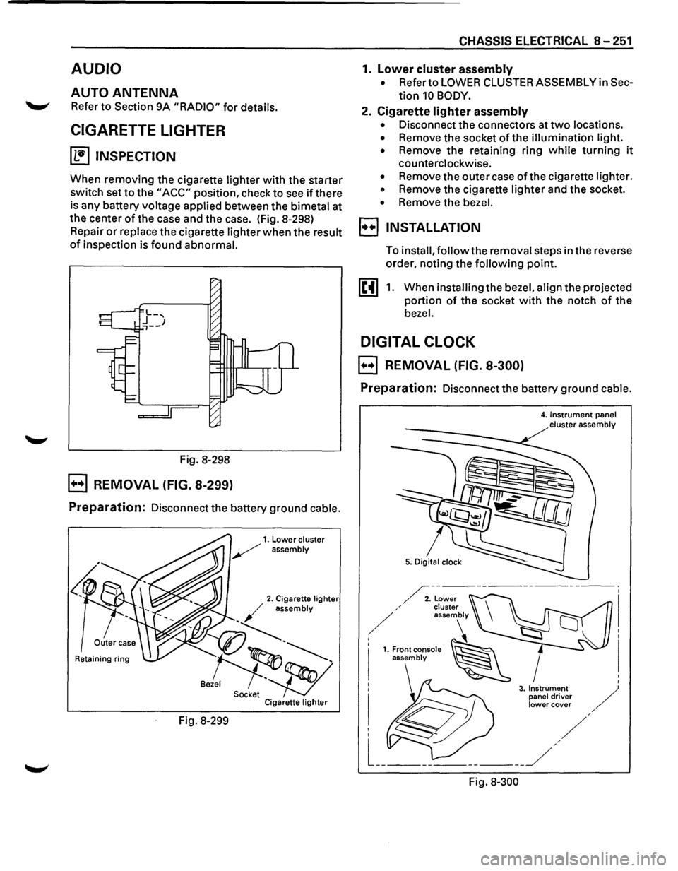
~ INSPECTION
When removing the cigarette lighter with the starter
switch set
to the "ACC" position, check to see if there
is any battery voltage applied between the bimetal at
the center
of the case and the case. (Fig. 8-298)
Repair
or replace the cigarette lighter when the result
of inspection is found abnormal.
Fig. 8-298
B REMOVAL (FIG. 8-299)
Preparation: Disconnect the battery ground cable.
Retaining ring
Fig. 8-299
CHASSIS ELECTRICAL 8-251
1. lower cluster assembly
• Refer to LOWER CLUSTER ASSEMBLY in Sec
tion 10 BODY.
2. Cigarette lighter assembly
• Disconnect the connectors at two locations.
• Remove the socket of the illumination light.
•
Remove the retaining ring while turning it
counterclockwise.
• Remove the outer case of the cigarette lighter.
• Remove the cigarette lighter and the socket.
• Remove the bezel.
I••! INSTALLATION
To install, follow the removal steps in the reverse
order, noting the
following point.
1. When installing the bezel, align the projected
portion
of the socket with the notch of the
bezel.
DIGITAL CLOCK
B REMOVAL (FIG. 8-300)
Preparation: Disconnect the battery ground cable.
Fig.
8-300
4. Instrument panel cluster assembly
Page 1442 of 1928
8-252 CHASSIS ELECTRICAL
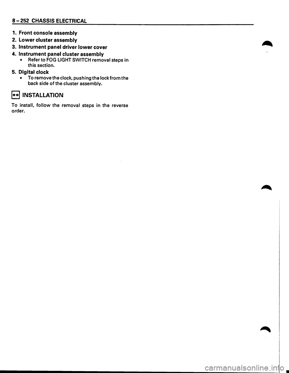
1. Front console assembly
2. Lower cluster assembly
3. Instrument panel driver lower cover
4. Instrument panel cluster assembly
• Refer to FOG LIGHT SWITCH removal steps in
this section.
5. Digital clock
• To remove the clock, pushing the lock from the
back side
of the cluster assembly.
E) INSTALLATION
To install, follow the removal steps in the reverse
order.
Page 1474 of 1928
8-284 CHASSIS ELECTRICAL
ANTI-THEFT INDICATOR
~ INSPECTION
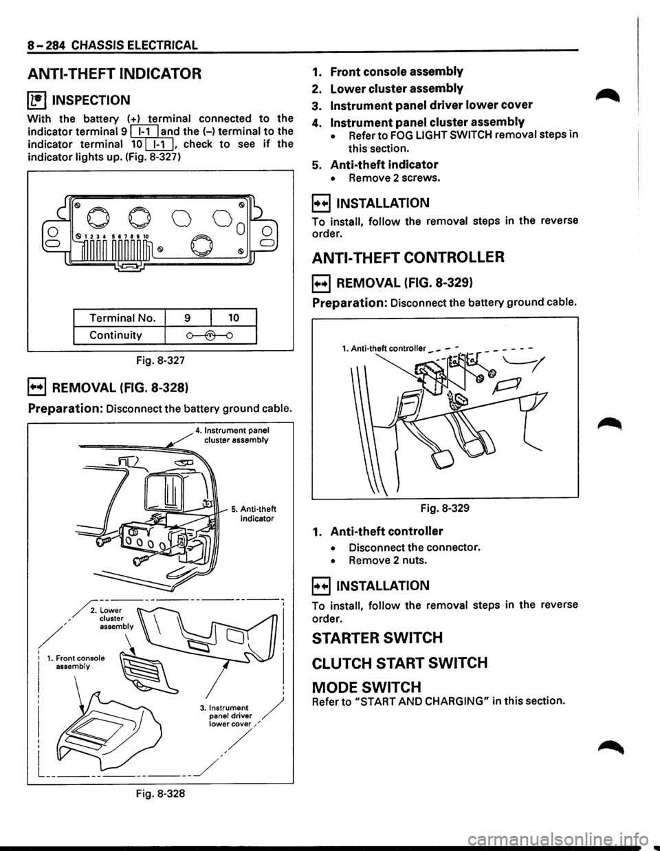
With the battery (+) terminal connected to the
indicator
terminal 9 ~l'ld the H terminal to the
indicator
terminal 10[EIJ, check to see if the
indicator
lights up. (Fig. 8-327)
Terminal No. 9 10
Continuity
Fig. 8-327
B REMOVAL (FIG. 8-328)
Preparation: Disconnect the battery ground cable.
4. Instrument panel cluster assembly
-====-==============~!!;!;::,..
Fig. 8-328
5. Anti-theft
indicator
1. Front console assembly
2. lower cluster assembly
3. Instrument panel driver lower cover
4. Instrument panel cluster assembly
• Refer to FOG LIGHT SWITCH removal steps in
this section.
5. Anti-theft indicator
• Remove 2 screws.
B INSTALLATION
To install, follow the removal steps in the reverse
order.
ANTI-THEFT CONTROLLER
B REMOVAL (FIG. 8-329)
Preparation: Disconnect the battery ground cable.
Fig. 8-329
1. Anti-theft controller
• Disconnect the connector.
• Remove 2 nuts.
B INSTALLATION
To install, follow the removal steps in the reverse
order.
STARTER SWITCH
CLUTCH START SWITCH
MODE SWITCH
Refer to "START AND CHARGING" in this section.
Page 1508 of 1928
8-318 CHASSIS ELECTRICAL
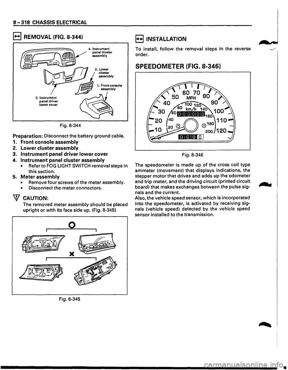
B REMOVAL (FIG. 8-344)
3. Instrument
panel driver lower cover
Fig. 8-344
4. Instrument
panel cluster
assembly
Preparation: Disconnect the battery ground cable.
1. Front console assembly
2. Lower cluster assembly
3. Instrument panel driver lower cover
4. Instrument panel cluster assembly
• Refer to FOG LIGHT SWITCH removal steps in
this section.
5. Meter assembly
• Remove four screws of the meter assembly.
•
Disconnect the meter connectors.
W CAUTION:
The removed meter assembly should be placed
upright or with its face side up. (Fig. 8-345)
0
)(
Fig. 8-345
B INSTALLATION
To install, follow the removal steps in the reverse
order.
SPEEDOMETER (FIG. 8-346)
Fig. 8-346
The speedometer is made up
of the cross coil type
ammeter (movement)
that displays indications, the
stepper
motor that drives and adds up the odometer
and
trip meter, and the driving circuit (printed circuit
board) that makes exchanges between the
pulse sig
nals and the current.
Also, the vehicle speed sensor, which is incorporated
into the speedometer, is activated
by receiving sig
nals (vehicle speed) detected by the vehicle speed
sensor
installed to the transmission.
•
Page 1572 of 1928
8-382 CHASSIS ELECTRICAL
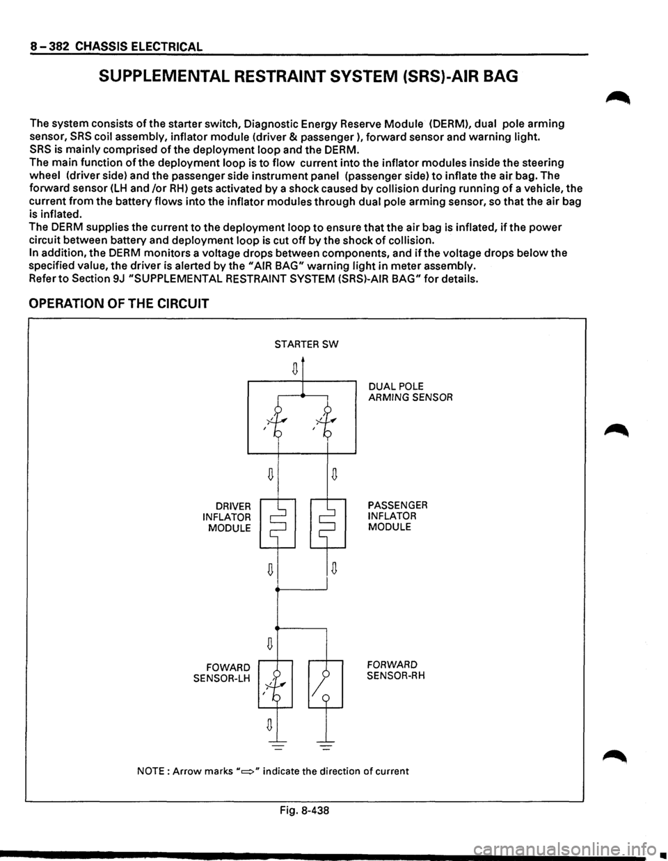
SUPPLEMENTAL RESTRAINT SYSTEM (SRS)-AIR BAG
The system consists of the starter switch, Diagnostic Energy Reserve Module (OERM), dual pole arming
sensor,
SRS coil assembly, inflator module (driver & passenger), forward sensor and warning light.
SRS is mainly comprised of the deployment loop and the DERM.
The main function of the deployment loop is to flow current into the inflator modules inside the steering
wheel (driver side) and the passenger side instrument panel (passenger side) to inflate the air bag. The
forward sensor
(LH and /or RH) gets activated by a shock caused by collision during running of a vehicle, the
current
from the battery flows into the inflator modules through dual pole arming sensor, so that the air bag
is
inflated.
The DERM supplies the current to the deployment loop to ensure that the air bag is inflated, if the power
circuit between battery and deployment loop is cut off by the shock of collision.
In
addition, the DERM monitors a voltage drops between components, and if the voltage drops below the
specified
value, the driver is alerted by the "AIR BAG" warning light in meter assembly.
Refer to Section 9J "SUPPLEMENTAL RESTRAINT SYSTEM (SRS)-AIR BAG" for details.
OPERATION OF THE CIRCUIT
DRIVER
INFLATOR MODULE
FOWARD
SENSOR-LH
D
D
STARTER SW
D
1
DUAL POLE ARMING SENSOR
PASSENGER
INFLATOR
MODULE
FORWARD
SENSOR-RH
NOTE: Arrow marks "c::::>" indicate the direction of current
Fig. 8-438
•
Page 1614 of 1928
9B-30 CRUISE CONTROL
1. Front console assembly
• Remove four screws.
• Remove the transmission shift lever knob.
• Remove the transfer shift lever knob.
• Disconnect the seat heater switch connectors
(If so equipped).
• Disconnect the "POWER & WINTER" switch
connectors (A/T only).
2. Lower cluster assembly
• Remove three screws.
• Disconnect the cigar lighter connectors.
• Remove the cigar lighter illumination bulb
socket.
• Disconnect the ashtray illumination bulb
connector.
3. Instrument panel driver lower cover
• Remove the engine hood opener.
• Remove three screws and clip.
•
Disconnect four fasteners.
4. Steering cowl
• Remove seven screws.
5. Starter switch
• Disconnect the connector.
• Remove the screw.
8 INSTALLATION
To install, follow the removal steps in the reverse
order noting the following point.
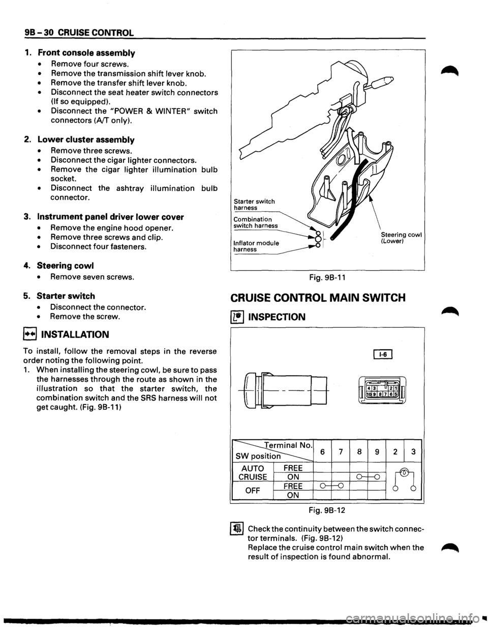
1. When installing the steering cowl, be sure to pass
the harnesses
through the route as shown in the
illustration so that the starter switch, the
combination switch and the SRS harness will not
get caught. (Fig. 98-11)
Starter switch
harness
Combination
switch harness
l._n!~~~o!_ module __..o .~ ~
Fig. 98-11
Steering cowl (Lower)
CRUISE CONTROL MAIN SWITCH
(1!1 INSPECTION
OI1
r-="'
-L
r= t-------uii4J~l "ltl1 u
l
1111ilr9Tsl7lels .,
:::o.,..o-
~ s 6 7 8 9 2 3
AUTO FREE
n
CRUISE ON ()-1---n
OFF FREE o-f--0
ON
Fig. 98-12
ltjl Check the continuity between the switch connec
tor terminals. (Fig. 98-12)
Replace the cruise control main switch when the ~
result of inspection is found abnormal.
Page 1615 of 1928
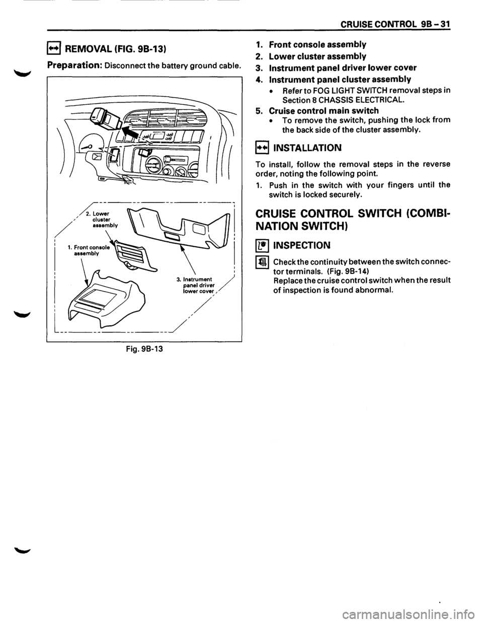
B REMOVAL (FIG. 98-13)
Preparation: Disconnect the battery ground cable.
Fig.
98-13
CRUISE CONTROL 98-31
1. Front console assembly
2. Lower cluster assembly
3. Instrument panel driver lower cover
4. Instrument panel cluster assembly
• Refer to FOG LIGHT SWITCH removal steps in
Section 8 CHASSIS ELECTRICAL.
5. Cruise control main switch
• To remove the switch, pushing the lock from
the back side of the cluster assembly.
B INSTALLATION
To install, follow the removal steps in the reverse
order, noting the
following point.
1. Push in the switch with your fingers until the
switch is locked securely.
CRUISE CONTROL SWITCH (COMBI
NATION SWITCH)
(b!] INSPECTION
I till Check the continuity between the switch connec
tor terminals. (Fig. 98-14)
Replace the cruise control switch when the result
of inspection is found abnormal.
Page 1618 of 1928
98-34 CRUISE CONTROL
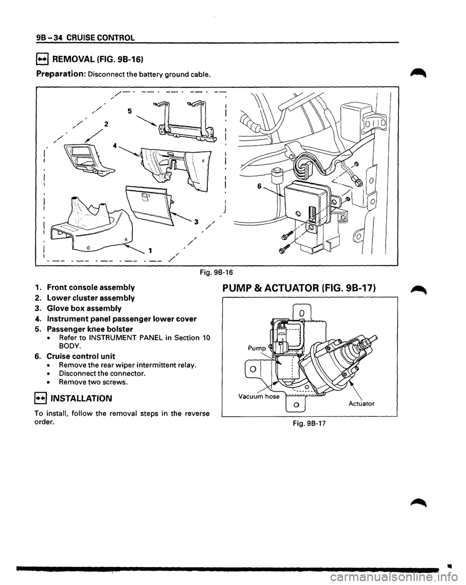
B REMOVAL (FIG. 98-16)
Preparation: Disconnect the battery ground cable.
/-----/
I
J
Fig. 98-16
1. Front console assembly
2. Lower cluster assembly
3. Glove box assembly
4. Instrument panel passenger lower cover
5. Passenger knee bolster
• Refer to INSTRUMENT PANEL in Section 10
BODY.
6. Cruise control unit
• Remove the rear wiper intermittent relay.
• Disconnect the connector.
• Remove two screws.
E) INSTALLATION
To install, follow the removal steps in the reverse
order.
PUMP & ACTUATOR (FIG. 98-17)
Actuator
Fig. 98-17
..
Page 1627 of 1928
Supplemental Restraint System 9J-3
GENERAL DESCRIPTION
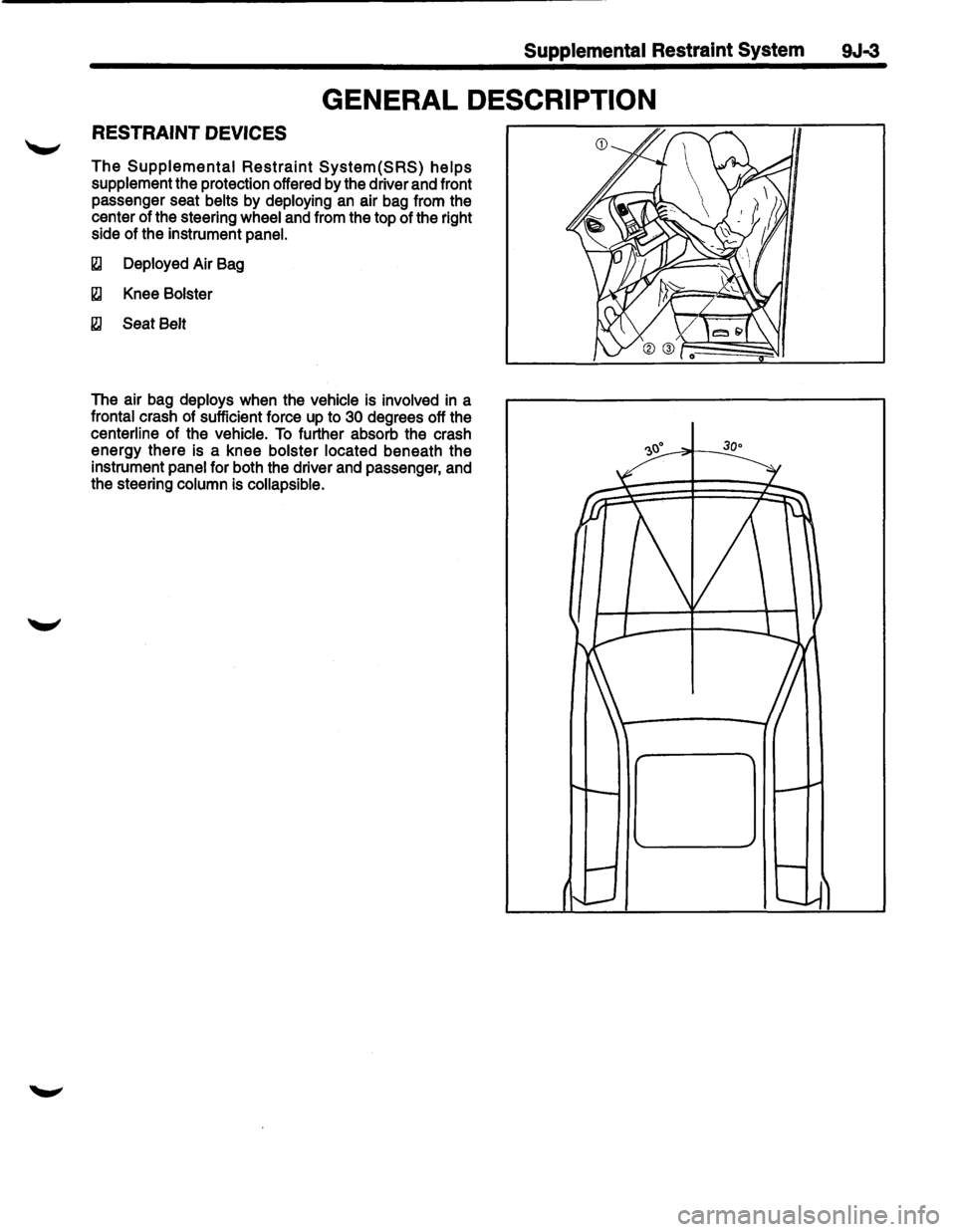
RESTRAINT DEVICES
The Supplemental Restraint System(SRS) helps
supplement the protection offered by the driver and front
passenger seat
belts by deploying an air bag from the
center of the steering
wheel and from the top of the right
side of the instrument
panel.
~ Deployed Air Bag
~ Knee Bolster
~ Seat Belt
The air bag deploys when the vehicle is involved in a
frontal crash of sufficient force up to 30 degrees off the
centerline of the vehicle. To further absorb the crash
energy there is a knee
bolster located beneath the
instrument
panel for both the driver and passenger, and
the steering
column is collapsible.
Page 1631 of 1928
SRS COIL ASSEMBLY
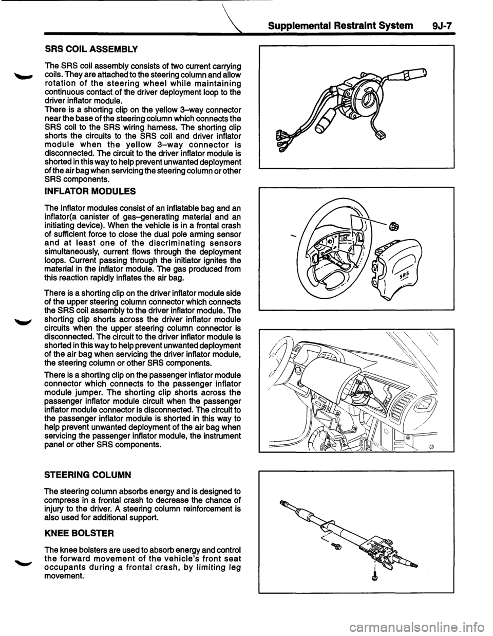
The SRS coil assembly consists of two current carrying
coils. They are attached to the steering column and allow
rotation of the steering wheel while maintaining
continuous contact of the driver deployment loop to the
driver inflator module.
There is a shorting clip on the yellow
3-way connector
near the base of the steering column which connects the
SRS coil to the SRS wiring harness. The shorting clip
shorts the circuits to the
SRS coil and driver inflator
module when the yellow 3-way connector is
disconnected. The circuit to the driver inflator module is
shorted
in this way to help prevent unwanted deployment
of the air bag when servicing the steering column or other
SRS components.
INFLATOR MODULES
The inflator modules consist of an inflatable bag and an
inflator(a canister of gas-generating material and an
initiating device). When the vehicle is in a frontal crash
of sufficient force to close the dual pole arming sensor
and at least one of the discriminating sensors
simultaneously, current flows through the deployment
loops. Current passing through the initiator ignites the
material
in the inflator module. The gas produced from
this reaction rapidly inflates the air bag.
There is a shorting clip
on the driver inflator module side
of the upper steering column connector which connects
the
SRS coil assembly to the driver inflator module. The
shorting clip shorts across the driver inflator module
circuits when the upper steering column connector is
disconnected. The circuit to the driver inflator module is
shorted
in this way to help prevent unwanted deployment
of the air bag when servicing the driver inflator module,
the steering column
or other SRS components.
There is a shorting clip on the passenger inflator module
connector which connects to the passenger inflator
module jumper. The shorting clip shorts across the
passenger inflator module circuit when the passenger
inflator module connector is disconnected. The circuit to
the passenger inflator module is shorted in this way to
help prevent unwanted deployment of the air bag when
servicing the passenger inflator module, the instrument
panel or other
SRS components.
STEERING COLUMN
The steering column absorbs energy and is designed to
compress in a frontal crash to decrease the chance of
injury to the driver. A steering column reinforcement is
also used for additional support.
KNEE BOLSTER
The knee bolsters are used to absorb energy and control
the forward movement of the vehicle's front seat
occupants during a frontal crash, by limiting leg
movement.
Supplemental Restraint System 9J-7