instrument panel ISUZU TROOPER 1995 Repair Manual
[x] Cancel search | Manufacturer: ISUZU, Model Year: 1995, Model line: TROOPER, Model: ISUZU TROOPER 1995Pages: 1928
Page 1662 of 1928
9J-38-~tal Restraint System
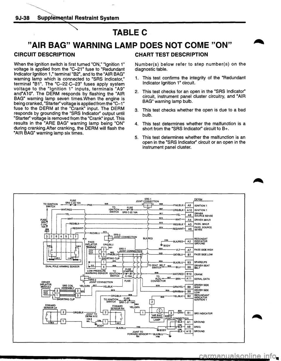
TABLE C
"AIR BAG" WARNING LAMP DOES NOT COME "ON"
CIRCUIT DESCRIPTION
When the ignition switch is first turned "ON," "Ignition 1"
voltage is applied from the "C-21" fuse to "Redundant
Indicator Ignition 1 ,"terminal "B2", and to the "AIR BAG"
warning lamp which is connected to "SRS Indicator,"
terminal "B1".
The "C-22·C-23" fuses apply system
voltage to the "Ignition 1" inputs, terminals "A9"
and"A10". The DERM responds by flashing the "AIR
BAG"
warning lamp seven times.When the engine is
being cranked,
"Starter'' voltage is applied from the "C-1"
fuse to the DERM at the "Crank" input. The DERM
responds by grounding the
"SRS Indicator'' output until
"Starter" voltage
is removed from the "Crank" input. This
results in the "ARE BAG" warning lamp being "ON"
during cranking.After cranking, the DERM will flash the
"AIR BAG" warning lamp six times.
TO IGNITION
SWITCH
FUSEj
SRS C-24 10A-
1Bot RD
FUSE SRS C-23 10A ,. ..
CHART TEST DESCRIPTION
Number(s) below refer to step number(s) on the
diagnostic table.
1. This test confirms the integrity of the "Redundant
Indicator Ignition 1" circuit.
2. This test checks for an open in the "SRS Indicator"
circuit, instrument panel cluster circuitry, and "AIR
BAG"
warning lamp bulb.
3. This test checks whether the open is due to a bad
bulb.
4. This test determines whether the malfunction is a
short from the
"SRS Indicator'' circuit to B+.
5. This test determines whether the malfunction is an
open in the "SRS Indicator'' circuit or an open in the
instrument
panel cluster.
SRS-1 JOINT CONNECTION
1834
IGNITION 1 IGNITION 1 DRIVER SOURCE SENSE DRIVER 36VLR PASS. 36VLR
REDUNDAT
INDICATOR GROUND
PASS
SIDE HIGH
PASS
SIDE LOW
1---''""""'-------'l-----l--'1-~--'TO ~&'Jc~ELT 1833 BLU FUSE N-7-ST.,AR_TE.,_R+-'l---'1----"''"'"'-"---WHT/RED C-1 0A Al'6L ____.Jill_ BAN FUSE CONNECTOR 1819
1820
SERIAL DATA
DRIVER SIDE HIGH DRIVER SIDE LOW REDUNDANT INDICATOR
IGNITION 1
SRS INDICA TOR
•
Page 1741 of 1928
Supplemental Restraint System 9J-117
SERVICE PRECAUTIONS
CAUTION: WHEN PERFORMING SERVICE ON OR
AROUND SRS COMPONENTS OR SRS WIRING,
FOLLOW
THE PROCEDURES LISTED BELOW TO
TEMPORARILY
DISABLE THE SRS. FAILURE TO
FOLLOW PROCEDURES COULD RESULT IN
POSSIBLE AIR BAG DEPLOYMENT, PERSONAL
INJURY OR OTHERWISE UNNEEDED SRS
REPAIRS.
The DERM in Driver-Passenger SRS can maintain
sufficient voltage to cause a deployment for up to 2
minutes after the ignition switch is turned to
"OFF," the
battery is disconnected, or the fuse powering the DERM
is removed.
Many of the service procedures require removal of the
"AIR BAG" fuse, and disconnection of the inflator
modules from the deployment loop to avoid an accidental
deployment.
If the inflator module is disconnected from
the deployment loop as noted in the "Disabling the
SRS"
procedure that follows, service can begin immediately
without waiting for the 2 minute time period to expire.
DISABLING THE SRS
REMOVAL
• Turn the steering wheel so that the vehicle's wheels
are pointing straight ahead.
• Turn the ignition switch to "OFF"
1. Remove SRS fuse C-21, C-22, C-23 and C-24 from
left dash side lower fuse block.
2. Disconnect yellow
3-way connector at the base of
the steering column.
3. Remove
liP compartment door assembly, Refer to
"Passenger inflator module replacemenf' in section
9J-135.
4. Disconnect yellow 4-way connector behind the liP
compartment door assembly.
NOTE
• With the" AIR BAG" fuse removed and ignition switch
"ON," the "AiR BAG" warning lamp will be "ON." This
is normal operation and does not indicate
an SRS
malfunction.
ENABLING THE SRS
INSTALLATION
Turn ignition switch to "LOCK" and remove key.
1. Connect yellow 4-way connector of passenger
inflator module.
2. Install liP compartment door assembly, Refer to
"Passenger inflator module replacement" in section
9J-3.
3. Connect yellow 3-way connector at the base of the
steering column.
4. Install" AIR BAG" fuse C-21, C-22, C-23 and C-24 to
left dash side lower fuse block.
Tum ignition switch to
"RUN" and verify that the "AIR
BAG"
warning lamp flashes seven times and then turns
"OFF" If it does not operate as described, perform the
"SRS Diagnostic System Check" in section 9J-32.
HANDLING/INSTALLATION/DIAGNOSIS
1. Inflator modules should not be subjected to
temperatures above 65°C(150°F).
2. Discriminating s~nsors, inflator modules, arming
sensors, or DERMs should not be used if they have
been dropped from a height of 1
00 centimeters (3.28
feet) or more.
3. When a discriminating sensor or arming sensor is
replaced, it MUST be oriented with the arrow
on the
sensor pointing toward the front of the vehicle.
It is
very important for the discriminating sensors and
arming sensor to be located flat on the mounting
surface, parallel to the vehicle datum line.
It is
important that the sensor mounting surface is free of
any dirt or other foreign material.
4. Do not apply power to the SRS unless all
components are connected or a diagnostic chart
requests it, as this
will set a diagnostic trouble code.
5. The
"SRS Diagnostic System Check'' must be the
starting point of any SRS diagnostics. The
"SRS
Diagnostic System Check" will verify proper "AIR
BAG" warning lamp operation and will lead you to the
correct chart to diagnose any SRS malfunctions.
Bypassing these procedures may result in extended
diagnostic time, incorrect diagnosis, and incorrect
parts replacements.
INSPECTIONS REQUIRED AFTER ACCI
DENT
CAUTION: CERTAIN SRS COMPONENTS MUST BE
REPLACED AFTER A FRONTAL
CRASH INVOLVING
AIR
BAG DEPLOYMENT.
In all types of accident regardless of "Air Bag"
deployment, visually inspect all the following
components and their points and replace as required:
- Passenger
Inflator Module
- Steering wheel
- SRS coil assembly
- Steering column
- Knee bolster and
Instrument panel mounting
Page 1746 of 1928
9J-122 Supplemental Restraint System
DUAL POLE ARMING SENSOR
WARNING: DURING SERVICE PROCEDURES, BE VERY CAREFUL WHEN HANDLING A SENSOR. NEVER ~
STRIKE OR JAR A SENSOR. UNDER SOME CIRCUMSTANCES, IT COULD CAUSE DEPLOYMENT AND
RESULT IN PERSONAL INJURY OR IMPROPER OPERATION OF THE SUPPLEMENTAL RESTRAINT SYSTEM(
SRS
). ALL SENSOR AND MOUNTING BRACKET BOLTS MUST BE CAREFULLY TORQUED TO ASSURE
PROPER OPERATION. NEVER POWER
UP THE SRS WHEN ANY SENSOR IS NOT RIGIDLY ATTACHED TO
VEHICLE, SINCE
THE SENSOR COULD BE ACTIVATED WHEN NOT ATTACHED AND COULD RESULT IN
DEPLOYMENT.
WARNING: PROPER OPERATION OF THE SENSORS AND SUPPLEMENTAL RESTRAINT SYSTEM( SRS)
REQUIRES
THAT ANY REPAIRS TO THE VEHICLE STRUCTURE RETURN IT TO ITS ORIGINAL PRODUCTION
CONFIGURATION.
DEPLOYMENT (CURRENT CODE 51 )OR ANY VISIBLE DAMAGE TO SENSOR AND/OR
THEIR MOUNTING
BRACKETS REQUIRES REPLACEMENT, NOT REPAIR. PROPER OPERATION OF A
SENSOR ALSO REQUIRES THAT SENSOR BE RIGIDLY BOLTED TO THE VEHICLE STRUCTURE. THE ARROW
ON
THE SENSOR MUST BE POINTING TOWARD THE FRONT OF THE VEHICLE. FAILURE TO OBSERVE
THESE PRECAUTIONS CAN RESULT IN IMPROPER SRS OPERATION AND POSSIBLE LACK OF
SUPPLEMENTAL RESTRAINT PROTECTION FOR THE DRIVER AND PASSENGER DURING AN ACCIDENT
IMPACT.
All
sensors are specifically calibrated and are keyed to the sensor location and SRS wiring harness. Caution should
be used to ensure proper location of the sensors. The keying of the sensor to their locations and wiring harness
connectors should never be modified
in the filed.
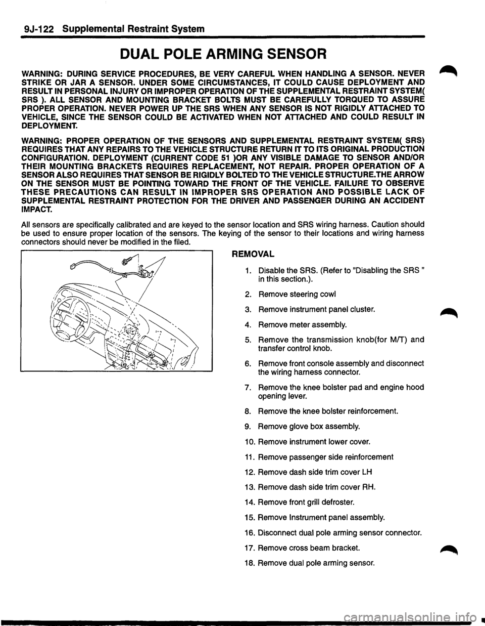
REMOVAL
1. Disable the SRS. (Refer to "Disabling the SRS "
in this section.).
2. Remove steering
cowl
3. Remove instrument panel cluster. ~
4. Remove meter assembly.
5. Remove the transmission knob(for Mff) and
transfer control knob.
6. Remove front console assembly and disconnect
the wiring harness connector.
7. Remove the knee bolster pad and engine hood
opening lever.
8. Remove the knee bolster reinforcement.
9. Remove glove box assembly.
10. Remove instrument lower cover.
11. Remove passenger side reinforcement
12. Remove dash side trim cover
LH
13. Remove dash side trim cover RH.
14. Remove front grill defroster.
15. Remove
Instrument panel assembly.
16. Disconnect
dual pole arming sensor connector.
17. Remove cross beam bracket.
18. Remove
dual pole arming sensor.
II
Page 1747 of 1928
INSTALLATION
1. Install dual pole arming sensor and tighten to
specified torque.
Torque: 26N·m(19 lb·ft.).
2. Install cross beam bracket.
3. Connect dual pole arming sensor connector.
4. Install instrument panel assembly.
5. Install front grill defroster.
6. Install dash side trim cover RH.
7. Install dash side trim cover LH.
8.
Install passenger side reinforcement
9. Install instrument lower cover.
1
0. Install glove box assembly.
11. Install the knee bolster reinforcement.
12.
Install the knee bolster pad and engine hood
opening
lever.
13. Install front console assembly and connect the
wiring harness connector.
14.
Install the transmission knob(for M/T) and
transfer control knob.
15.
Install meter assembly.
16. Install instrument panel cluster.
17. Install steering cowl
18. Enable the SRS (Refer to "Enabling the SRS" in
this section.).
Supplemental :Restraint System 9J-123
Page 1759 of 1928
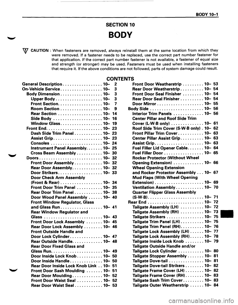
BODY 10-1
SECTION 10
BODY
\V CAUTION : When fasteners are removed, always reinstall them at the same location from which they
were removed. If a fastener needs to be replaced, use the correct part number fastener for
that application. If the correct part number fastener is not available, a fastener of equal size
and strength (or stronger)
may be used. Fasteners must be used when installing fasteners
that require it. If the above conditions are not followed, parts of system damage could result.
CONTENTS
General Description ................. 10-2 Front Door Weatherstrip ......... 10-53
On-Vehicle Service .................. 10-3 Rear Door Weatherstrip .......... 10-54
Body Dimension .................. 10-3 Front Door Seal Finisher ......... 10-54
Upper Body .................... 10-3 Rear Door Seal Finisher .......... 10-54
Front Section ................... 10-7 Door Mirror .................... 10-55
Room Section .................. 10-9 Body Side ....................... 10-56
Rear Section ................... 10-14 Interior Trim Panels ............. 10-56
Side Body ..................... 10-16 Center Pillar and Roof Side Trim
Window Glass .................. 10-19 Cover (L·W·B only) .............. 10-61
Front End ........................ 10-23 Roof Side Trim Cover (S·W·B only) . 10-62
Dash Side Trim Panel ............ 10-23 Front Pillar Trim Cover ........... 10-63
Assist Grip ..................... 10-23 Center Pillar Assist Grip .......... 10-63
Consoles ...................... 10-24 Assist Grip ..................... 10-63
Instrument Panel Assembly ....... 10-25 Fuel Filler lid Opener Cable ....... 10-64
Cross Beam Assembly ........... 10-30 Fuel Filler Door ................. 10-65
Doors ........................... 10-32 Rocker Protector (Without Wheel
Front Door Assembly ............ 10-32 Opening Extension) ............. 10-66
Rear Door Assembly ............. 10-32 Wheel Opening Extension
Door Strikers ................... 10-33 and Rocker Protector Assembly ... 10-67
Door Check Arm Assembly Mud Flaps (With Wheel Opening
(Front & Rear) .................. 10-34 Extension) ..................... 10-69
Front Door Trim Panel ........... 10-35 Ventilation Assembly ............ 10-70
Rear Door Trim Panel ............ 10-38 Quarter Flipper Glass Assembly
Door Wood Panel Assembly ...... 10-40 (S·W·B) ........................ 10-71
Front Window Regulator, Glass Rear End ........................ 10-72
and Glass Run .................. 10-41 Tailgate Assembly (LH) .......... 10-72
Rear Window Regulator and Tailgate Assembly (RH) .......... 10-73
Glass ......................... 10-43 Tailgate Strikers ................ 10-75
Front Door Lock Assembly ....... 10-45 Tailgate Trim Panel (LH) .......... 10-75
Rear Door Lock Assembly ........ 10-46 Tailgate Trim Panel (RH) .......... 10-76
Front Outside Handle and Tailgate Lock Assembly (LH) ...... 10-77
Door Lock Cylinder .............. 10-47 Tailgate Lock Assembly (RH) ...... 10-78
Rear Outside Handle ............. 10-48 Tailgate Inside Lock Knob ........ 10-79
Rear Door Fixed Glass and Tailgate Outside Handle and/or
Glass Run ...................... 10-49 Tailgate Lock Cylinder ........... 10-80
Door Inside Lock Knob ........... 10-50 Tailgate Stopper Assembly ....... 10-81
Door Inside Handle .............. 10-50 Tailgate Dove-tail ............... 10-81
Rear Door Inside Lock Knob Link .. 10-51 Tailgate Dove-tail Strikers ........ 10-82
Front Door Sash Moulding ....... 10-51 Tailgate Frame Cover (LH) ........ 10-82
Rear Door Moulding ............. 10-52 Tailgate Frame Cover (RH) ........ 10-83
Front Door Waist Seal ........... 10-52 Tailgate Sash Trim Cover ......... 10-83
Rear Door Waist Seal ............ 10-53 Tailgate Outer Weatherstrip ...... 10-84
Page 1783 of 1928
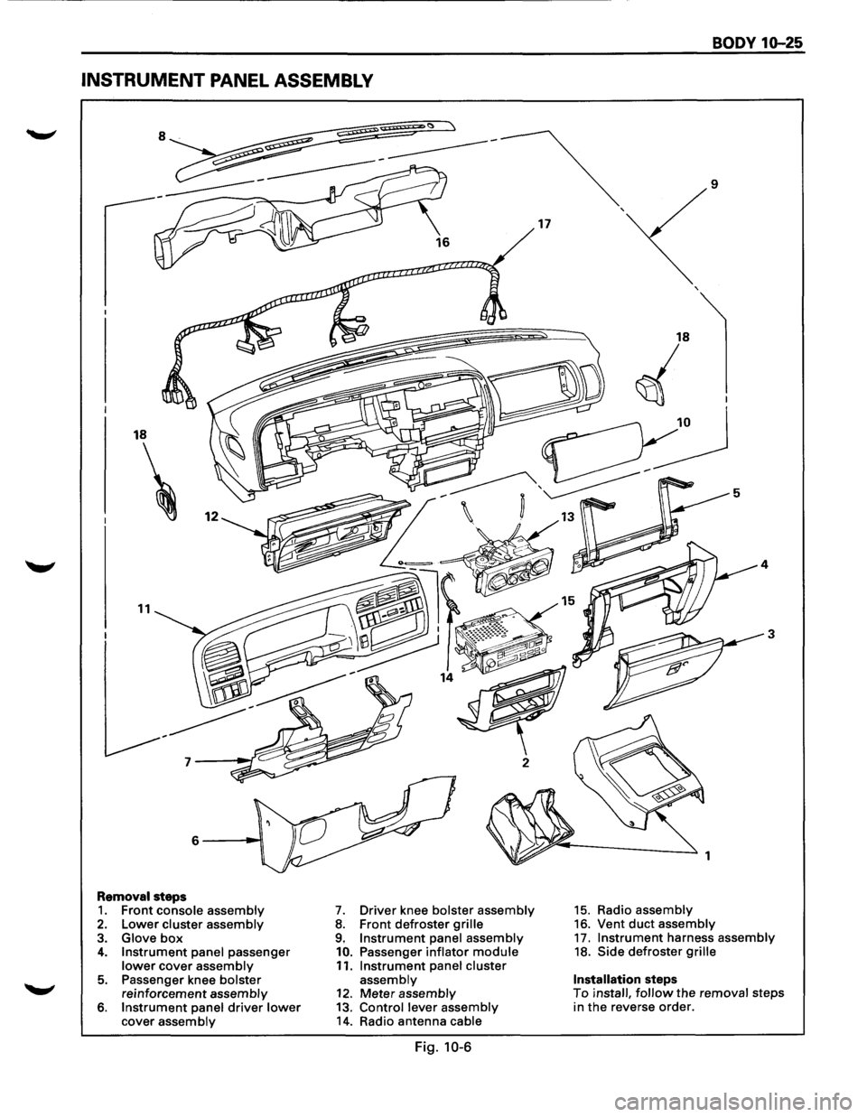
INSTRUMENT PANEL ASSEMBLY
18
11
Removal steps 1. Front console assembly 2. Lower cluster assembly 3. Glove box 4. Instrument panel passenger lower cover assembly
5. Passenger knee bolster reinforcement assembly 6. Instrument panel driver lower cover assembly
7. Driver knee bolster assembly 8. Front defroster grille 9. Instrument panel assembly
10. Passenger inflator module 11. Instrument panel cluster assembly 12. Meter assembly 13. Control lever assembly 14. Radio antenna cable
Fig. 10-6
17
BODY 10-25
9
3
1
15. Radio assembly 16. Vent duct assembly 17. Instrument harness assembly 18. Side defroster grille
Installation steps To install, follow the removal steps
in the reverse order.
Page 1784 of 1928
10-26 BODY
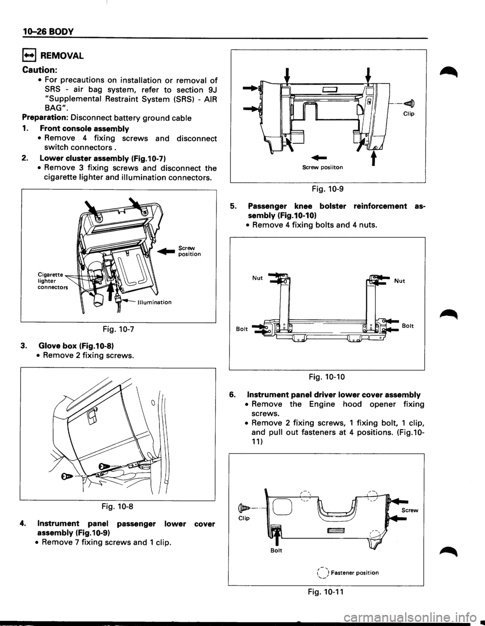
l••l REMOVAL
Caution:
• For precautions on installation or removal of
SRS -air bag system, refer to section 9J
"Supplemental Restraint System (SRS) -AIR
BAG".
Preparation: Disconnect battery ground cable
1. Front console assembly
•
Remove 4 fixing screws and disconnect
switch connectors .
2. Lower cluster assembly (Fig.10-7)
• Remove 3 fixing screws and disconnect the
cigarette
lighter and illumination connectors.
Cigarette ~c--!H---1\.+.....,. lighter connectors
Fig. 10-7
3. Glove box (Fig.10-8)
• Remove 2 fixing screws.
Fig.
10-8
4. Instrument panel passenger lower cover
assembly (Fig.10-9)
• Remove 7 fixing screws and 1 clip.
--41llj])
Clip
Screw posi iton
Fig. 10-9
5. Passenger knee bolster reinforcement as
sembly (Fig.10-10)
• Remove 4 fixing bolts and 4 nuts.
Bolt
Fig. 10-10
6. Instrument panel driver lower cover assembly
•
Remove the Engine hood opener fixing
screws.
• Remove 2 fixing screws, 1 fixing bolt, 1 clip,
and pull out fasteners at 4 positions. (Fig.10-
11)
@ate----
Clip
Bolt
{-J Fastener position '--
Fig. 10-11
..
Page 1785 of 1928
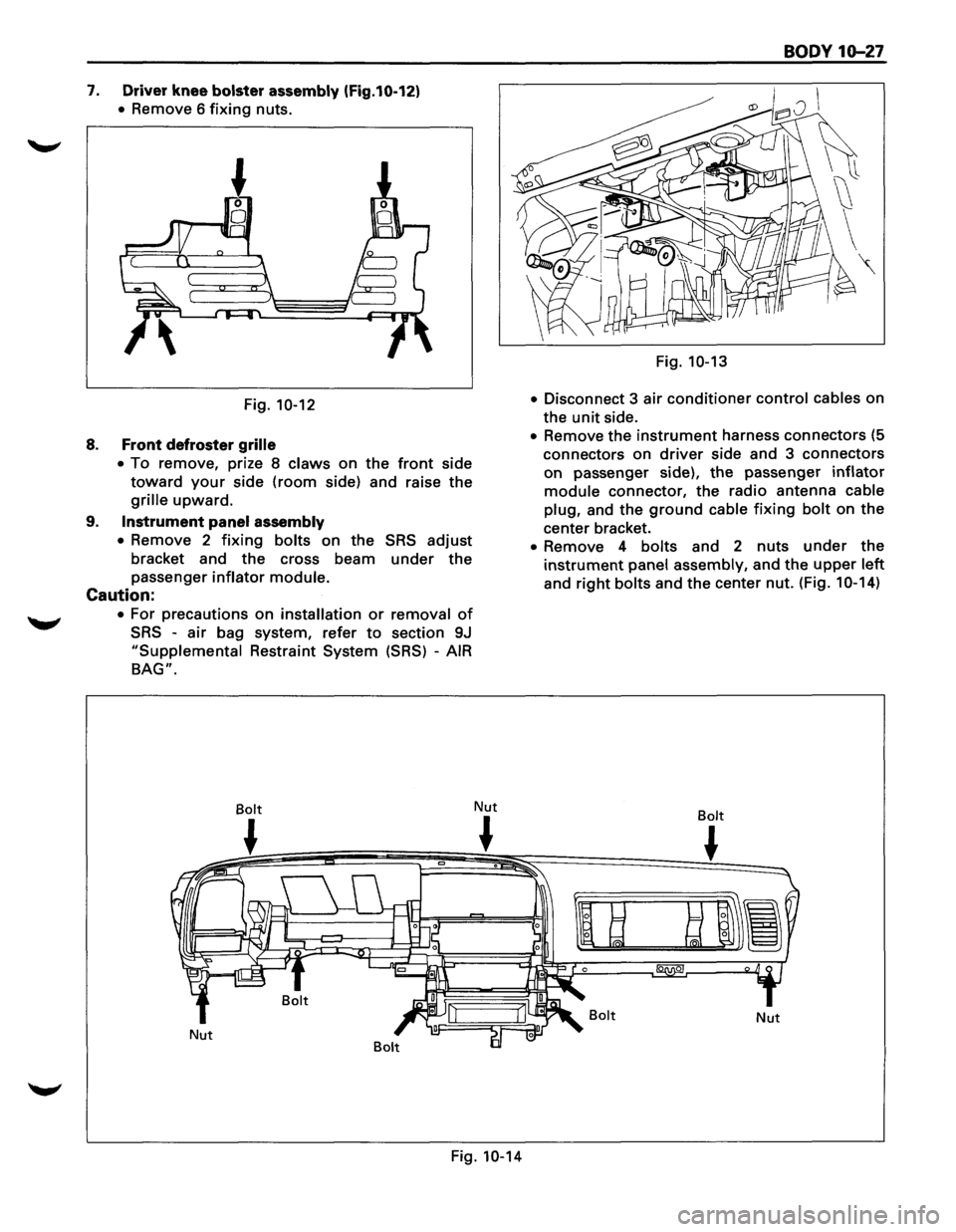
7. Driver knee bolster assembly (Fig.10-12)
• Remove 6 fixing nuts.
Fig.
10-12
8. Front defroster grille
•
To remove, prize 8 claws on the front side
toward your side (room side) and raise the
grille upward.
9. Instrument panel assembly
•
Remove 2 fixing bolts on the SRS adjust
bracket and the cross beam under the
passenger inflator module.
Caution:
• For precautions on installation or removal of
SRS -air bag system, refer to section 9J
"Supplemental Restraint System (SRS) -AIR
BAG".
Bolt
~
Nut Nut
~
Fig. 10-14
BODY 10-27
Fig. 10-13
•
Disconnect 3 air conditioner control cables on
the
unit side.
• Remove the instrument harness connectors (5
connectors on
driver side and 3 connectors
on passenger side), the passenger inflator
module connector, the radio antenna cable
plug,
and the ground cable fixing bolt on the
center bracket.
• Remove 4 bolts and 2 nuts under the
instrument panel assembly, and the upper left
and right bolts and the center nut. (Fig. 1 0-14)
Bolt
~
Bolt Nut
Page 1786 of 1928
10-28 BODY
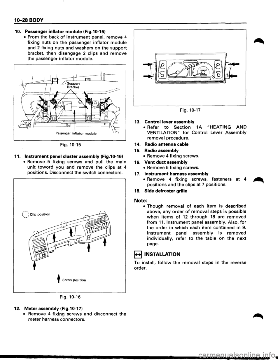
10. Passenger inflator module (Fig.10-15)
• From the back of instrument panel, remove 4
fixing nuts on the passenger inflator module
and 2 fixing nuts and washers on the support
bracket, then disengage 2 clips and remove
the passenger
inflator module.
Passenger inflator module
Fig. 10-15
11. Instrument panel cluster assembly (Fig.10-16)
• Remove . 5 fixing screws and pull the main
unit toward you and remove the clips at 4
positions. Disconnect the switch connectors.
,.-, I ) Clip position --~
t Screw position
Fig. 10-16
12. Meter assembly (Fig.10-17)
• Remove 4 fixing screws and disconnect the
meter harness connectors. Fig.
10-17
13. Control lever
assembly
• Refer to Section 1A "HEATING AND
VENTILATION" for Control Lever Assembly
removal procedure.
14. Radio antenna cable
15. Radio assembly
• Remove 4 fixing screws.
16.
Vent duct assembly
• Remove 5 fixing screws.
17.
Instrument harness assembly
• Remove 4 fixing screws, fasteners at 4 ~
positions and the clips at 7 positions.
18.
Side defroster grille
Note:
• Though removal of each item is described
above, any
order of removal steps is possible
when items of 12 through 18 are removed
from 11. Instrument panel assembly. Also, for
the order in which each item contained in 9.
Instrument panel assembly is removed
individually, refer to the table on the next
page.
I+•IINSTALLATION
To install, follow the removal steps in the reverse
order.
II
Page 1787 of 1928
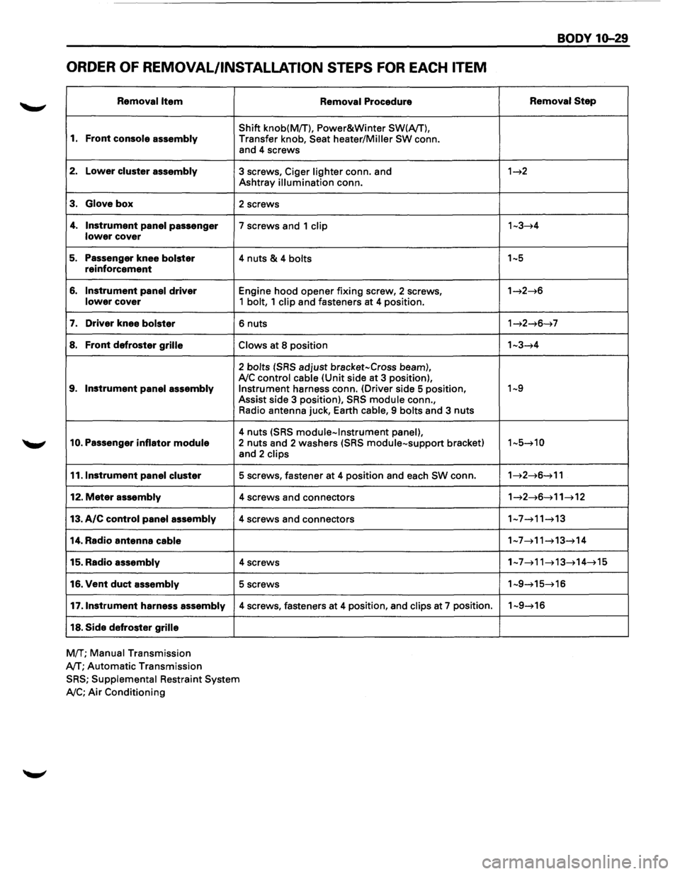
ORDER OF REMOVAL/INSTALLATION STEPS FOR EACH ITEM
Removal Item
1. Front console assembly
2. Lower cluster assembly
3. Glove box
4. Instrument panel passenger lower cover
5. Passenger knee bolster reinforcement
6. Instrument panel driver lower cover
7. Driver knee bolster
8. Front defroster grille
9. Instrument panel assembly
10. Passenger inflator module
11.1nstrument panel cluster
12. Meter assembly
13. A/C control panel assembly
14. Radio antenna cable
15. Radio assembly
16. Vent duct assembly
17 .Instrument harness assembly
18. Side defroster grille
MfT; Manual Transmission
A/T;
Automatic Transmission Removal
Procedure
Shift
knob(MfT), Power&Winter SW(A/T),
Transfer knob, Seat heater/Miller SW conn.
and 4 screws
3 screws, Ciger lighter conn. and
Ashtray illumination conn.
2 screws
7 screws and 1 clip
4 nuts & 4 bolts
Engine hood opener fixing screw, 2 screws, 1 bolt, 1 clip and fasteners at 4 position.
6 nuts
Claws at 8 position
2 bolts (SRS adjust bracket-Cross beam), A!C control cable (Unit side at 3 position), Instrument harness conn. (Driver side 5 position,
Assist side 3 position), SRS module conn.,
Radio antenna juck, Earth
cable, 9 bolts and 3 nuts
4 nuts (SRS module-Instrument panel), 2 nuts and 2 washers (SRS module-support bracket)
and 2 clips
5 screws, fastener at 4 position and each SW conn.
4 screws and connectors
4 screws and connectors
4 screws
5 screws
4 screws, fasteners at 4 position, and clips at 7 position.
SRS; Supplemental Restraint System
A!C; Air Conditioning
BODY 10-29
Removal Step
1~2
1~3~4
1~5
1~2~6
1~2~6~7
1-3~4
1~9
1-5~10
1~2~6~11
1~2~6~11~12
1-7~11~13
1-7~11~13~14
1~7~11~13~14~15
1-9~15~16
1-9~16