coolant temperature ISUZU TROOPER 1995 Manual PDF
[x] Cancel search | Manufacturer: ISUZU, Model Year: 1995, Model line: TROOPER, Model: ISUZU TROOPER 1995Pages: 1928
Page 992 of 1928
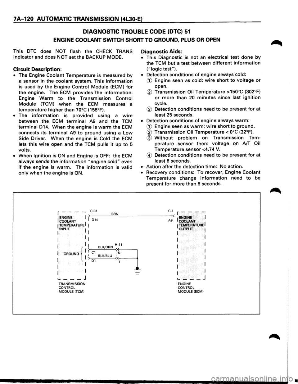
7A-120 AUTOMATIC TRANSMISSION (4L30-E)
DIAGNOSTIC
TROUBLE CODE (DTC) 51
ENGINE COOLANT SWITCH SHORT TO GROUND, PLUS OR OPEN
This DTC does NOT flash the CHECK TRANS
indicator and does NOT set the BACKUP MODE.
Circuit Description:
• The Engine Coolant Temperature is measured by
a sensor in the coolant system. This information
is used by the Engine Control Module (ECM) for
the engine. The ECM provides the information:
Engine Warm to the Transmission Control
Module (TCM) when the ECM measures a
temperature
higher than 70°C (158°F).
• The information is provided using a wire
between the ECM terminal A9 and the TCM
terminal D14. When the engine is warm the ECM
connects its terminal A9 to ground using a Low
Side Driver. When the engine is Cold the ECM
lets this wire open and the TCM pulls it up to 5
volts.
•
When Ignition is ON and Engine is OFF: the ECM
always sends the information "engine cold" even
if the engine is warm. The information is valid
only when the engine is ON.
Diagnostic Aids:
• This Diagnostic is not an electrical test done by
the TCM but a test between different information
("logic test").
• Detection conditions of engine always cold:
CD Engine! seen as cold: wire short to voltage or
open.
@ Transmission Oil Temperature >150°C (302°F)
or more than 20 minutes since last ignition
cycle.
@ Detection conditions need to be present for at
least 25 seconds.
• Detection conditions of engine always warm:
CD Engine! seen as warm: wire short to ground.
@ Transmission Oil Temperature< ooc (32°F).
@ Without problem on Transmission Tem
perature sensor then:
voltage on AfT Oil
Temperature sensor <4.74 V.
@ Detection conditions need to be present for at
least 6 seconds.
• Action after the detection time: No action.
• Recovery conditions: To recover, Engine Coolant
Temperature change information need to be
present
for more than 6 seconds.
r - - - -C·91 BRN C-1 r - - - -
I ~~~ENT I f,_D_1_4 __ ~.!__--------~-: I ~NGt~~ I
1 teMPERAtuRE I 1
1 t=R'ATJJRel
I INPUT I I I OUTP\:IT l
I 1
1 I I
I I I H-11 I l
I
GROUND 11 ? C1 BLKJORN ~9 I I I I BLKJBLU ( 1 I > o1 I
I I 1 I I
I I I I
~---J ~---J TRANSMISSION ENGINE
CONTROL CONTROL
MODULE
(TCM) MODULE (ECM)
•
Page 1214 of 1928
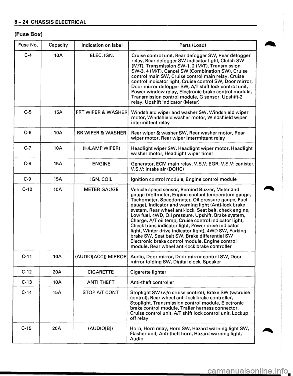
8-24 CHASSIS ELECTRICAL
(Fuse Box)
Fuse No.
Capacity Indication on label Parts (Load)
C-4 10A
ELEC.IGN. Cruise control unit, Rear defogger SW, Rear defogger
relay, Rear
defo9ger SW indicator light, Clutch SW
(M{T), Transmission SW-1, 2 (M!T), Transmission
SW-3, 4 (M{T), Cancel
SW (Combination SW), Cruise
control main
SW, Cruise control main relay, Cruise
control indicator light, Cruise control
SW, Door mirror,
Door mirror defogger SW, AfT shift lock control unit,
Power window relay, Electronic brake control module,
Transmission control module, G sensor, Upshift-2
relay, Upshift indicator (Meter)
C-5 15A FRTWIPER &WASHER
Windshield wipt~r and washer SW, Windshield wiper
motor, Windshit~ld washer motor, Windshield wiper
intermittent relay
C-6 10A RR WIPER & WASHER
Rear wiper & washer SW, Rear washer motor, Rear
wiper motor, Rear wiper intermittent relay
C-7 10A (H/LAMP WIPER) Headlight wiper SW, Headlight wiper motor, Headlight
washer motor, Headlight
wiper timer
C-8 15A ENGINE Generator, ECM main relay, V.S.V; EGA, V.S.V: canister,
V.S.V: intake air
(DOHC)
C-9 15A IGN. COIL Ignition control module, Engine control module
C-10 10A METER GAUGE Vehicle speed stmsor, Remind Buzzer, Meter and
gauge
(Voltmeter, Engine coolant temperature gauge,
Tachometer, Speedometer,
Oil pressure gauge, Fuel
gauge),
Indicator and warning light (Anti-lock brake
system, Rear wheel anti-lock, Seat belt, check engine,
Low fuel, 4WD,
Oil pressure, Upshift, Brake system,
Charge,
AfT oil temp, Cruise control indicator light,
Check trans indicator light,
Power drive indicator
light,
Winter drive indicator light), 4WD SW, Parking
brake SW, Seat belt SW, Brake differential SW
Electronic brake control module, Engine control
module, Rear wheel anti-lock brake controller
C-11 10A (AUDIO[ACCJ) MIRROR Audio, Door mirror, Door mirror control SW, Door
mirror folding SW, Digital clock, Speaker
C-12 20A CIGARETTE Cigarette lighter
C-13 10A
ANTI THEFT Anti-theft controller
C-14 15A
STOP AfT CONT Stoplight SW (w/o cruise control), Brake SW (w/cruise
control), Rear wheel anti-lock brake controller,
Stoplight, Transmission control module, Electronic
brake control module, Trailer harness connector,
Cruise control unit,
AfT shift lock control unit, Lockup
off relay
C-15
20A (AUDIO[B]) Horn,
Horn relay, Horn SW, Hazard warning light SW,
Flasher unit, Anti-theft horn, Hazard warning light,
Audio
•
Page 1238 of 1928
.~·-
, ca· CIO I O'l O'l
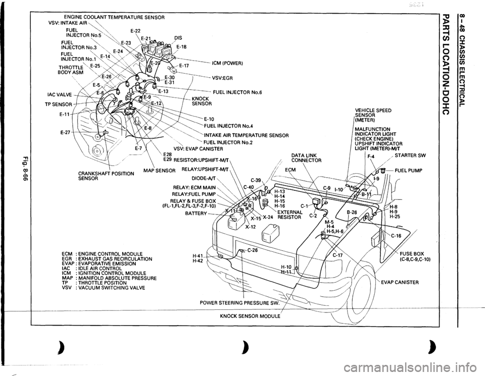
ENGINE
COOLANT TEMPERATURE SENSOR
VSV:
INTAKE
AIR~""-"-,
FUEL
~,
'"-
E-22
INJECTOR
No.5
'~~
FUEL
~
"':·.E-23
INJECTOR
No.3
"-
'"<
FUEL
"-
·,,,
E-~
4 /'
INJECTOR
No.'1'~-
1~4 "...
.......
. .......
' '
/
BODY
ASM
"-..'-
>
DIS / / E-18
ICM !POWER)
THROTILE '
E-~5·.-..,
.. '-, ·,/
r
E-2~,,
/E-5v~~;>o~~
--vsv:EGR
FUEL
INJECTOR
No.6
E-11
~E-10 ~FUEL
INJECTOR
No.4
E-27-+
"'
:1
~
.........
_
'-......
"·INTAKE
AIR TEMPERATURE SENSOR
ECM EGR EVAP
lAC
ICM MAP TP vsv )
X
·"
~
FUEL
INJECTOR
No.2
VSV: EVAP CANISTER
E28
E29
RESISTOR:UPSHIFT-M/T
CRANKSHAFT
POSITION
SENSOR
MAP
SENSOR RELAY:UPSHIFT-M/T ,
ENGINE
CONTROL
MODULE
EXHAUST GAS RECIRCULATION
EVAPORATIVE EMISSION IDLE
AIR CONTROL
IGNITION CONTROL
MODULE
MANIFOLD ABSOLUTE PRESSURE
THROTILE POSITION VACUUM
SWITCHING
VALVE
DIODE-AfT
'...,
RELAY:
ECM
MAIN
~"'-.,'...,
RELAY:FUEL
PUMP
'....
'
RELAY
& FUSE BOX
(FL-1,FL-2,FL-3,F-2,F-10)
BATIERY~
H-41 H-42~
KNOCK SENSOR
MODULE
)
DATA
LINK
CONNECTOR
VEHICLE
SPEED
SENSOR
(METER)
MALFUNCTION INDICATOR LIGHT (CHECK ENGINE) UPSHIFT INDICATOR LIGHT
(METER)-M/T
STARTER
SW
·~FUEL
PUMP
EVAP CANISTER
)
~
co I
~
~ co
(/)
0
r-
:::t
0
)> C/)
0
C/)
~
Cii
-
m
0
r-m
2
0
I
~
c
:a
0
0 )>
J:
r-
0
Page 1241 of 1928
w " ~~ O.SLJY ~ ..
2"' a~ u$ ~f~ ~~ ~g~
FENDER-RH II
DUCT II
~~~~~II
DUCT II
INTAKE AIR TEMPERATURE SENSOR
~~ 0~
a; d
0.89
C-1 A&
THROTTLE POSITION
SENSOR
... 5! ., .. ::> 0: ~
m
0.85LIO
~ a d d
li~Ui"o:i UOlUCJI> i;i;i:b ~wuw "'"" ~ ~ g g
"' il " Ill
13
§
; w 0 0: .. 5N ~;:; 8<:1 d~ u"' ~~ ~~ ~~ z< ., .. ~g ~g
~ § :;1 ~ d
0: " Ill d
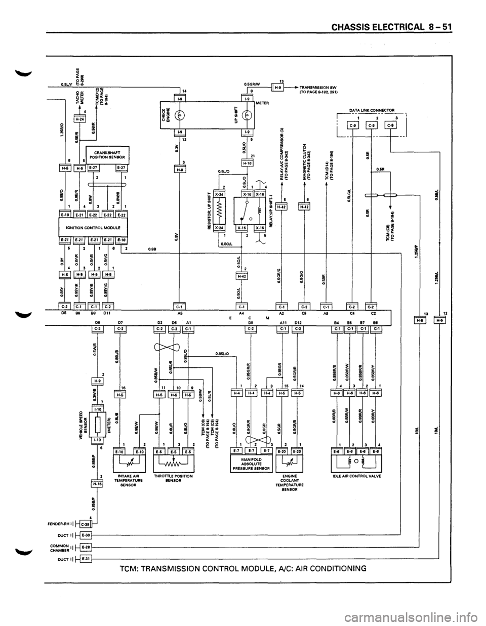
ENGINE COOLANT
TEMPERATURE
SENSOR
CHASSIS ELECTRICAL 8-51
~ ~ ~w _.,
i£ ~g
~ i ;zf d
d
IIi ~ d .. :b
~~ ~g
~
"' ~ 5I d "'
13 12 H-6 H-6
.. ~ "' ~ il il
!
! ! ~
~ ~ I ~ CD ! ! ~
i
i
TCM: TRANSMISSION CONTROL MODULE, A/C: AIR CONDITIONING
Page 1478 of 1928
8-288 CHASSIS ELECTRICAL
METER AND WARNING/INDICATOR LIGHT
GENERAL DESCRIPTION
The circuit consists of the starter switch, meter assembly, vehicle speed sensor, clutch switch, transmission
switch, lighting switch,
turn signal switch, thermo unit, oil pressure unit, Engine Control Module, fuel tank unit,
4WD
SW, oil pressure switch, parking brake switch, brake fluid switch, seat belt switch and illumination
controller.
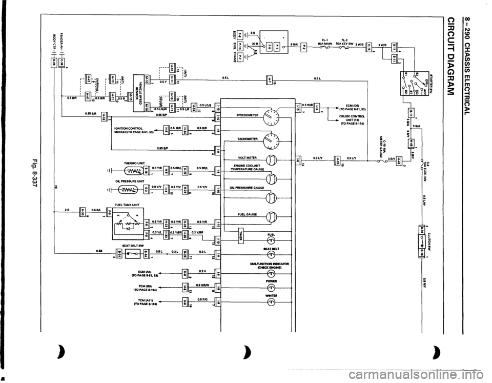
The meter ASM contains the speedometer, tachometer, voltmeter, engine coolant temperature gauge, oil
pressure gauge, fuel gauge and warning/indicator lights.
The meter warning/indicator lights and
their bulb sockets are a unit, they are installed from the back of the
speedometer assembly.
Page 1480 of 1928
•
, ce· CX) I w w .....
..
~ m
0
z
0 0 <
m
n
"'
-1
:D
"'
:z:
= ~~ :;; )
O.SIItll 2B
O.&B
ID
-,~
r
-•3
'
.. '
'
' ' IGNITION
CONTROL
MODULECTO
PAGE
S.S1,
531
ECMCASI
(TO PAGE
11-51,
531
TCMihl (TO PAGE
8-1t41
TCMIA111 (TO PAGE
11-1141
~[~} m[i] ~ .:. II
. 0 j[~}l
I'lL,
II"
:----~
.. :~.:,._
:
fill
:~
~~~~ I -··
.!., -
SPEEOOMETER TACHOMETER VOLTMETER ENGINE
COOLANT
TEMPERATURE
GAUGE
OIL PRESSUSRE
GAUGE
FUEL
GAUGE MALFUNCT10N
INDICATOR
lCHECKENGWEI
POWEll -TER
)
O.SL
ECMIDIII
ITO PAGE
11-51,
531
CRUISE
CONTROL UNITI131 ITO PAGE
11-1741
O.SLJY ;;
~ ~ '!' ;;: ~ ~ n ~ ~ )
n -:JJ n c =i c -)> G) :JJ )> 3:
co I N CD 0 (") :.t: > Cl) Cl) Cl) m ,.... m Q , n )> ,....
Page 1484 of 1928
8-294 CHASSIS ELECTRICAL
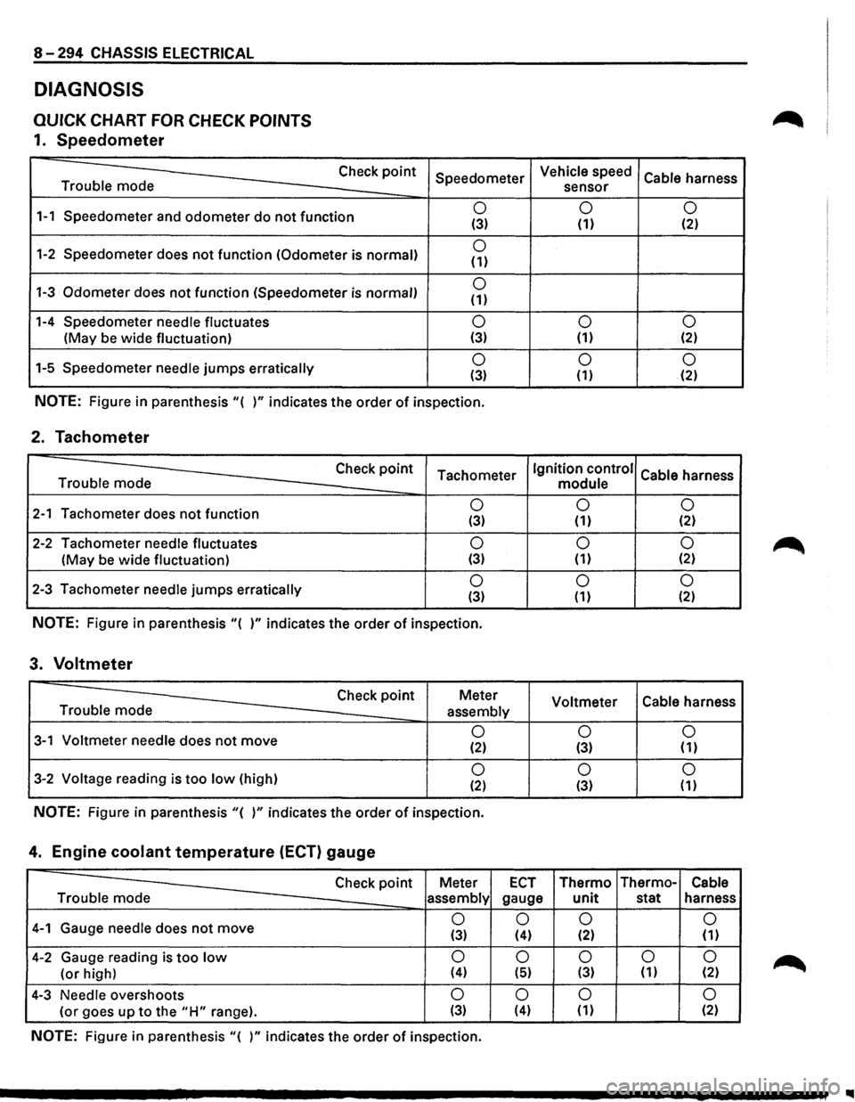
DIAGNOSIS
QUICK CHART FOR CHECK POINTS
1. Speedometer
Trouble mode Check
point
1-1 Speedometer
and odometer do not function
1-2 Speedometer does not function (Odometer is normal)
1-3 Odometer does not function (Speedometer is normal)
1-4 Speedometer needle fluctuates
(May be wide fluctuation)
1-5 Speedometer
needle jumps erratically Speedometer
0 (3)
0 (1)
0 (1)
0 (3)
0 (3)
NOTE: Figure
in parenthesis "( )" indicates the order of inspection.
2. Tachometer
Check point Tachometer Trouble mode
2-1 Tachometer does not function 0 (3)
2-2 Tachometer needle fluctuates 0
(May be wide fluctuation) (3)
2-3 Tachometer needle jumps erratically 0 (3)
NOTE: Figure in parenthesis "( )" indicates the order of inspection.
3. Voltmeter
Check point Meter
Trouble mode
assembly
3-1 Voltmeter needle does not move 0 (2)
3-2 Voltage reading is too low (high) 0 (2)
NOTE: Figure in parenthesis "( )" indicates the order of inspection.
4. Engine coolant temperature (ECT) gauge
Vehicle speed
Cable harness
sensor
0 0 (1) (2)
0
0 (1) (2)
0 0 (1) (2)
Ignition control
Cable harness
module
0 0
(1) (2)
0 0 (1) {2)
0 0 (1) (2)
Voltmeter Cable
harness
0 0 (3) (1)
0
0 (3) (1)
Check point Meter ECT Thermo Thermo-Cable
Trouble mode
assembly gauge unit stat harness
4-1 Gauge needle does not move 0
0 0
0
(3) (4) (2) (1)
4-2 Gauge reading is too low 0 0 0 0 0
(or high) (4) (5) (3) (1) (2)
4-3 Needle overshoots 0 0 0 0
(or goes up to the "H" range). (3) (4) (1) (2)
NOTE: Figure in parenthesis "( )" indicates the order of inspection.
..
Page 1492 of 1928
8-302 CHASSIS ELECTRICAL
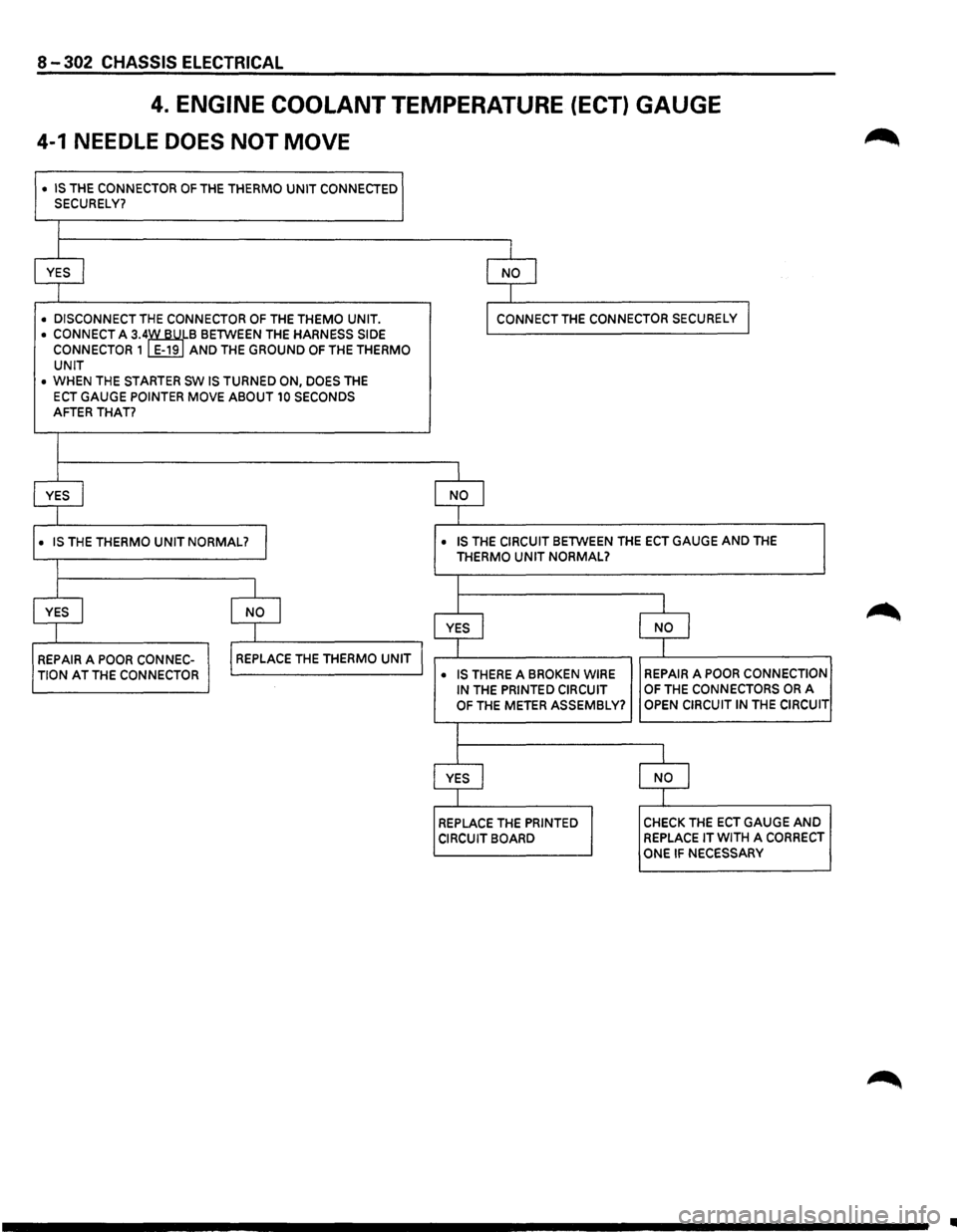
4. ENGINE COOLANT TEMPERATURE (ECT) GAUGE
4-1 NEEDLE DOES NOT MOVE
• IS THE CONNECTOR OF THE THERMO UNIT CONNECTED SECURELY?
I
YES I
I NO l
I
• DISCONNECT THE CONNECTOR OF THE THEMO UNIT. I CONNECT THE CONNECTOR SECURELY I
• CONNECT A 3.4~B BETWEEN THE HARNESS SIDE CONNECTOR 1 E-19 AND THE GROUND OF THE THERMO
UNIT
• WHEN THE STARTER SW IS TURNED ON, DOES THE
ECT GAUGE POINTER MOVE ABOUT 10 SECONDS AFTER THAT?
I
YES I NO I
1
• IS THE THERMO UNIT NORMAL? I • IS THE CIRCUIT BETWEEN THE ECT GAUGE AND THE
THERMO UNIT NORMAL?
I I
YES I
I NO I I I
YES I l I NO
REPAIR A POOR CONNEC-I REPLACE THE THERMO UNIT I T T
TION AT THE CONNECTOR • IS THERE A BROKEN WIRE REPAIR A POOR CONNECTION
IN THE PRINTED CIRCUIT OF THE CONNECTORS OR A
OF THE METER ASSEMBLY? OPEN CIRCUIT IN THE CIRCUIT
I
I l
YES I NO I
I l
REPLACE THE PRINTED CHECK THE ECT GAUGE AND
CIRCUIT BOARD REPLACE IT WITH A CORRECT
ONE IF NECESSARY
•
Page 1494 of 1928
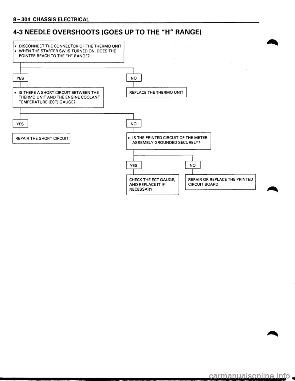
8-304 CHASSIS ELECTRICAL
4-3 NEEDLE OVERSHOOTS (GOES UP TO THE 11H" RANGE)
• DISCONNECT THE CONNECTOR OF THE THERMO UNIT • WHEN THE STARTER SW IS TURNED ON, DOES THE
POINTER REACH TO THE "H" RANGE?
I
I I
YES I NO I
I I
• IS THERE
A SHORT CIRCUIT BETWEEN THE REPLACE
THE THERMO UNIT THERMO UNIT AND THE ENGINE COOLANT TEMPERATURE (ECT) GAUGE?
I
I
I
YES I NO I
I I
REPAIR THE SHORT CIRCUIT I • IS THE PRINTED CIRCUIT OF THE METER
ASSEMBLY GROUNDED SECURELY?
I
I l
YES I NO I
I I
CHECK
THE ECT GAUGE, REPAIR OR REPLACE THE PRINTED
AND REPLACE IT IF CIRCUIT BOARD
NECESSARY
Page 1506 of 1928
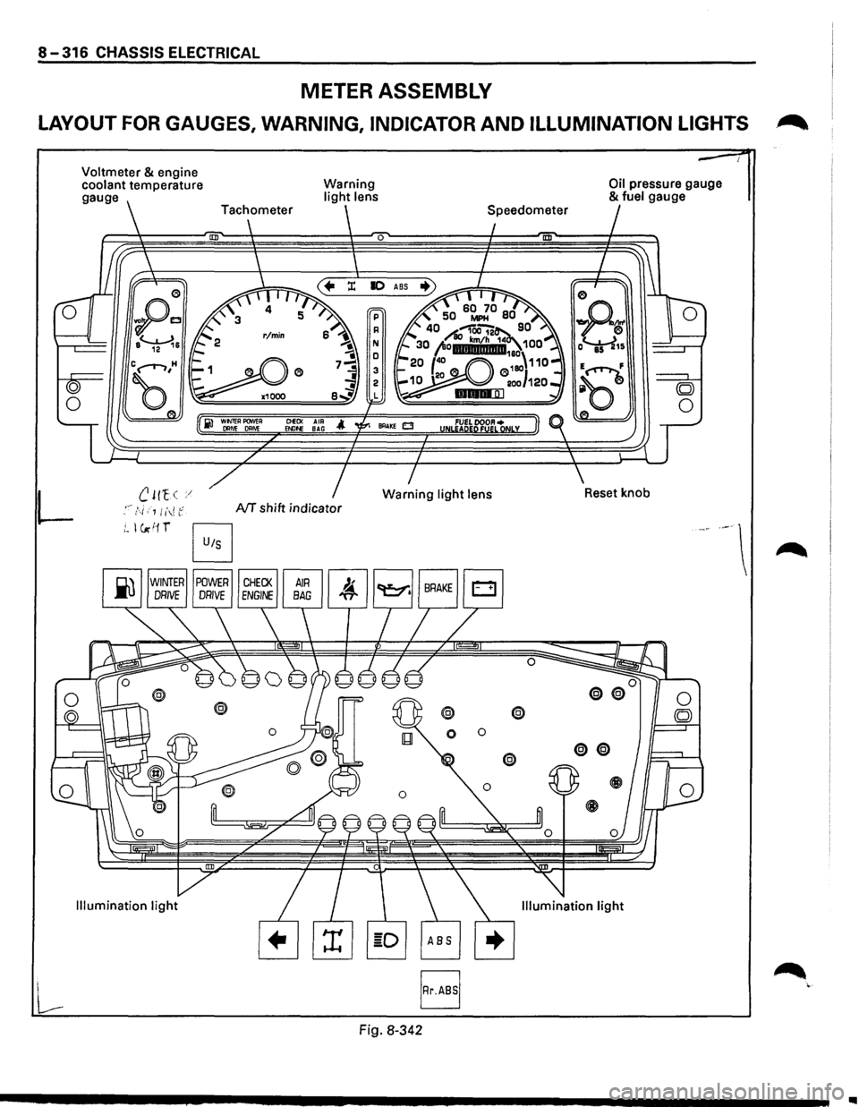
8-316 CHASSIS ELECTRICAL
METER ASSEMBLY
LAYOUT FOR GAUGES, WARNING, INDICATOR AND ILLUMINATION LIGHTS .~
L
Voltmeter & engine
coolant temperature
gauge
B
Warning light lens
0
ClEO< AIR Et.llf>E BAG
NT shift indicator
Fig. 8-342
@ @
0 0
Oil pressure gauge & fuel gauge
..