coolant temperature ISUZU TROOPER 1995 Repair Manual
[x] Cancel search | Manufacturer: ISUZU, Model Year: 1995, Model line: TROOPER, Model: ISUZU TROOPER 1995Pages: 1928
Page 876 of 1928
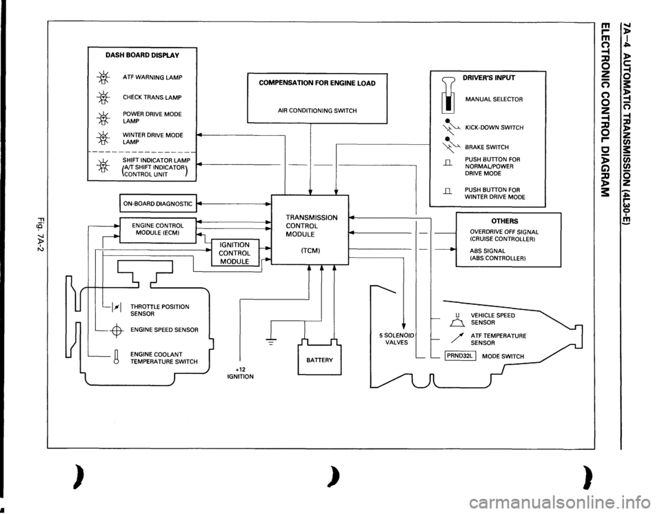
•
"'Tl c3' -..J )> I "'
~ )
DASH
BOARD
DISPLA
V
*
*
*
*
ATF
WARNING
LAMP
CHECK
TRANS
LAMP
POWER DRIVE MODE LAMP WINTER DRIVE MODE LAMP
~----------------
SHIFT INDICATOR
LAMP
COMPENSATION
FOR
ENGINE
LOAD
AIR CONDITIONING SWITCH
TI
DRIVER'S
INPUT
liJ
MANUAL
SELECTOR
~
KICK-DOWN SWITCH
" ~
BRAKE
SWITCH
*
(AfT
SHIFT INDICATOR)
CONTROL
UNIT
---
' ---
I-------------,
il
PUSH BUTTON
FOR
NORMALJPOWER
DRIVE MODE
ON-BOARD DIAGNOSTIC
j4
.. ,
..
l__l--1 L_-$-L_g
ENGINE CONTROL
MODULE
(ECM)
_ IGNITION
CONTROL
I
MODULE
i
THROTTLE POSITION
SENSOR
ENGINE SPEED SENSOR
l
I
I -
ENGINE COOLANT TEMPERATU~,_.TCH
)
I +12 IGNITION
• •
TRANSMISSION
CONTROL MODULE
(TCM)
j
L I
BATTERY
)
--
~
'
5SOLENOID VALVES
il
-·----·
___.
u
PUSH BUTTON
FOR
WINTER DRIVE MODE
OTHERS
OVERDRIVE
OFF
SIGNAL
(CRUISE CONTROLLER)
ABS
SIGNAL
(ABS CONTROLLER)
f.-
n_
VEHICLE SPEED
SENSOR
f-
/
ATF TEMPERATURE SENSOR
L__ L__
[PRNDJ2L
I MODE SWITCH
-
m
.....
r-
)>
m
I
(")
..;=...
-t
)>
;::g 0
c:
2
-1
-
0
(")
s:
(")
~
0
-
2
n
-t
-1
;::g
:a
0
)> z
r-
en
c
s:
:;
(i)
C)
en
~
0 z
3:
-..;=... r-w 0 I !!!
)
Page 878 of 1928
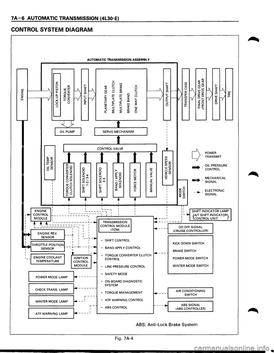
7A-6 AUTOMATIC TRANSMISSION (4L30-E)
CONTROL SYSTEM DIAGRAM
L1J ~ (!) z L1J
I
I
lr
t:··
~ .. I I
I
I
AUTOMATIC TRANSMISSION ASSEMBLY
O.:a: :Eo LLJ(J) t-z --' L1J oVl
ENGINE COOLANT TEMPERATURE
ffio ~---a:O wz >LLJ z--' oo uCJ> w::C :::>u at-a:=> ~d
0 0 z ... w, --'"' o-.. (J)N t-.!-u.. J: CJ)
IGNITION
CONTROL .
MODULE
~==PO=W==ER==M=O=D=E=L=A=M=P~r.-------
r-------CHECK TRANS. LAMP
~=W=IN=T=E=R=M=O=D=E=LA=M=P~~--J---
::c u L1J a: 1-:.:: ::c <( :::> <( u L1J --' a: 1-(!) u al :::> >-L1J L1J 0 --' 1-~ z u a: :5 <( ~ ~ --' al Cl.
Cl. L1J i=
i= L1J ~ z :.:: --' --' <( L1J :5 :::> :::> a: z Cl. ::!: ::!: al 0
0 a: L1J 0 >-0 > --'o --' z (l._ 1-<( L1J Cl.Q 0 > __,...,
SHIFT
CONTROL
BAND APPLY CONTROL
TORQUE CONVERTER CLUTCH CONTROL
LINE PRESSURE CONTROL
SAFETY MODE
ON-BOARD DIAGNOSTIC
SYSTEM
TORQUE MANAGEMENT
ATF WARNING CONTROL
r-ABS CONTROL
L--A-T_F_w_A_R_N_I_N_G_L_A_M_P_...Jr---_l 1---------------'
0 L1J "'a: Bio wVl __,z uw J:Vl L1J >
POWER c): TRANSMIT
.... : OIL PRESSURE
CONTROL
MECHANICAL
...• : SIGNAL
LLJJ: ou ELECTRONIC ot:: -•: ::!:~ SIGNAL
KICK DOWN SWITCH
BRAKE SWITCH
POWER MODE SWITCH
WINTER MODE SWITCH
AIR CONDITIONING
SWITCH
ABS
SIGNAL (ASS CONTROLLER)
ABS: Anti-Lock Brake System
Fig. 7A-4
..
Page 883 of 1928

AUTOMATIC TRANSMISSION (4L30-E) 7 A-11
FUNCTIONS OF INPUT /OUTPUT COMPONENTS
Components Function
Speed sensor
Senses rotation
of output shaft and feeds the data to Transmission
(fixed
to transmission (T/M)) Control Module (TCM)
Throttle Senses the extent of throttle valve opening and the speed of the throttle
position sensor (TPS) valve lever motion to open the valve and feeds the data to TCM (fed to
(fixed to engine)
Engine Control Module (ECM) also)
I
Brake Switch (SW) Senses whether the driver has pressed the brake pedal or not and feeds
N (fixed
to brake pedal) the
information to TCM
p Kick-down SW (fixed to Senses whether the driver has pushed the accelerator pedal fully or not
u accelerator pedal) and feeds the information to TCM
T Mode
SW (fixed to T/M) Senses the select lever position and feeds the information to TCM
s Power drive SW Senses whether the driver has selected the power mode and feeds the
I (fixed to front console) information to TCM
G T/M
oil temp. sensor
Senses the T/M oil temperature and feeds the data to TCM
N Engine
coolant Senses the engine cooling water temperature and feeds the data to TCM
A temperature
SW (feeds the signal from ECM)
L
Engine speed
signal Feeds the signals monitoring engine speed to TCM from Ignition Control
Module
(fed to ECM also)
Air conditioning Senses whether the air conditioner has been switched on or not and
information feeds the information
to TCM
On-board diagnostic
input By monitoring the Ground (GND), the location of failure is shown on the
T/M
monitor lamp ("CHECK TRANS") by flashing the diagnostic trouble
code
Winter switch
Senses whether the driver has selected the winter mode, and feeds the
(fixed
to front console) information to TCM
Cruise
controller Downshift takes place when Overdrive OFF signal is received from auto
(Overdrive
OFF signal) cruise control unit
Shift
solenoid Selects shift point and gear position suited to the vehicle running con-s 1-2/3-4, 2-3
dition on the basis of TCM output 0 Band apply solenoid
Controls oil flow suited to the vehicle running condition on the basis of L
E TCM output
0 N
Torque
Converter Controls clutch engagement/disengagement suited to the vehicle
u 0 Clutch solenoid running condition on the basis of TCM output
T I Force motor Adjusts the oil pump delivery pressure to line pressure suited to the p D
(Pressure regulator vehicle running condition on the basis of TCM output u valve) T
Power drive mode lamp
Informs the driver whether the vehicle is in power mode or not
s Winter drive mode lamp Informs the driver whether the vehicle is in winter mode or not
I T/M monitor lamp Informs the driver of failure in the system. It also displays the self diagnosis
G
("CHECK TRANS") code.
N Data Link Connector
(DLC) When connected with TECH 1 or tester, can communicate the data for A
L function
check, etc. (fed to ECM also). When TECH 1 is not connected, can
communicate the
signal for torque management with ECM.
Self-diagnosis connector
When short-circuited with the bipolar connector, the T/M monitor lamp
displays
a failure by code.
ATF warning
lamp Lights when ATF oil temperature rises.
ABS signal When the select lever is at "Reverse" or "L" range, sends a signal to the
ABS controller as one of the ABS control conditions.
Page 885 of 1928
AUTOMATIC TRANSMISSION (4L30-E) 7A-13
NORMAL OPERATION OF 1994-95 4L30-E TRANSMISSION
1. TORQUE CONVERTER CLUTCH (TCC)
APPLICATION CONDITIONS:
Engine coolant temperature must be above 70°C
(158°F).
Moreover, TCC is ON in 2nd gear during kick down
operation when engine coolant temperature is
above
70°C (158°F).
Also,
TCC is always ON in 2nd, 3rd & 4th gear when
transmission oil temperature is above 140°C
(284°F).
2. ATF WARNING LAMP
The ATF warning lamp will be constantly on (not
flashing) if the transmission oil temperature is
above
145°C (293°F).
The ATF warning lamp goes off again when the
transmission
oil temperature is below 125°C
(257°F).
3. SPECIAL SHIFT PATTERN WHEN THE
ENGINE IS COLD:
A special shift pattern is activated when the engine
coolant temperature is below 70°C (158°F). (3-4
shifts
for example are delayed for small throttle
openings and will occur a few MPH higher)
4. SHIFT ALTERATION WITH TECH1
DIAGNOSTIC TOOL CONNECTED:
Shifts will be harsh when TECH1 is connected to
TCM: Connection of TECH1 automatically forces
maximum line pressure during shifts only.
Page 913 of 1928
STALL TEST
The stall test allows you to check the transmission for
internal abrasion and the oneway clutch for slippage.
Torque converter performance can also be evaluated.
The
stall test results together with the road test results
will identify transmission components requiring ser
vicing or adjustment.
Stall Test Procedure:
1. Check the level of the engine coolant, the engine
oil, and the automatic transmission fluid.
Replenish
if necessary.
2. Block the wheels and set the parking brake.
3. Connect a tachometer to the engine.
4. Start the engine and allow it to idle until the
engine coolant temperature reaches
70 -8o·c
(158 -176.F).
5. Hold the brake pedal down as far as it will go.
6. Place the selector in the "D" range.
7. Gradually push the accelerator pedal to the floor.
The throttle valve
will be fully open.
Note the engine speed at which the tachometer
needle stabilizes.
Stall Speed
\fl NOTE:
2150 ± 150 rpm (SOHC)
2200 ± 150 rpm (DOHC)
VI Do not continuously run this test longer than 5
........, seconds.
8. Release the accelerator pedal.
9. Place the selector in the "N" range.
10. Run the engine at 1,200 rpm for one minute.
This
will cool the transmission fluid.
11. Repeat Steps 7-10 for the "3", "2", "L" and "R"
ranges.
AUTOMATIC TRANSMISSION (4L30-E) 7A-41
Page 914 of 1928
7 A-42 AUTOMATIC TRANSMISSION (4L30-E)
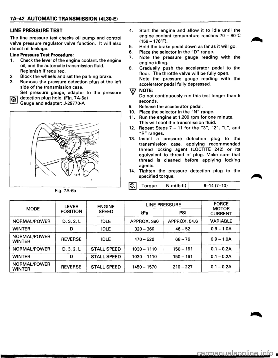
LINE PRESSURE TEST
The line pressure test checks oil pump and control
valve
pressure regulator valve function. It will also
detect oil leakage.
Line Pressure Test Procedure:
1. Check the level of the engine coolant, the engine
oil, and the automatic transmission fluid.
Replenish
if required.
2. Block the wheels and set the parking brake.
3. Remove the pressure detection plug at the left
side of the transmission case.
Set pressure gauge, adapter
to the pressure
l"iC\1 detection plug hole. (Fig. 7 A-6a)
~ Gauge and adapter: J-29770-A
Fig. 7A-6a
LEVER ENGINE
MODE
POSITION
SPEED
NORMAL/POWER D,3,2, L IDLE
WINTER D IDLE
NORMAL/POWER REVERSE IDLE WINTER
NORMAL/POWER
D,3,2,L STALL SPEED
WINTER D STALL SPEED
NORMAL/POWER REVERSE STALL SPEED WINTER
4.
5.
6.
7.
8.
9.
10.
11.
Start the engine and allow it to idle until the
engine
coolant temperature reaches 70 -80°C
(158-176°F).
Hold
the brake pedal down as far as it will go.
Place the selector in the "D" range.
Note the pressure gauge reading
with the
engine
idling.
Gradually
push the accelerator pedal to the
floor. The throttle valve will be fully open.
Note the pressure gauge reading
with the
accelerator
pedal fully depressed.
NOTE:
Do not continuously run this test longer than 5
seconds.
Release the accelerator pedal.
Place
the selector in the "N" range.
Run the engine at
1,200 rpm for one minute.
This
will cool the transmission fluid.
12. Repeat Steps 7-11 for the "3", "2", "L", and
"R" ranges.
13.
Install a pressure detection plug to the
transmission case,
applying recommended
thread
locking agent (LOCTITE 242) or its
equivalent to thread
of plug. Make sure that
thread is cleaned before applying locking
agents.
14. Tighten the pressure detection plug to the
specified torque.
~~~ Torque N·mOb·ft) / 9-14 (7-10)
LINE
PRESSURE FORCE
MOTOR kPa PSI CURRENT
APPROX. 380 APPROX. 54.6 VARIABLE
320-360 46-52 0.9 -1.0A
470-520 68-76 0.9 -1.0A
1030-1110 150-161 0.1-0.2A
1030-1110 150-161 0.1-0.2A
1450-1570 210-227 0.1-0.2A
•
Page 943 of 1928
AUTOMATIC TRANSMISSION (4L30-E) 7 A-71
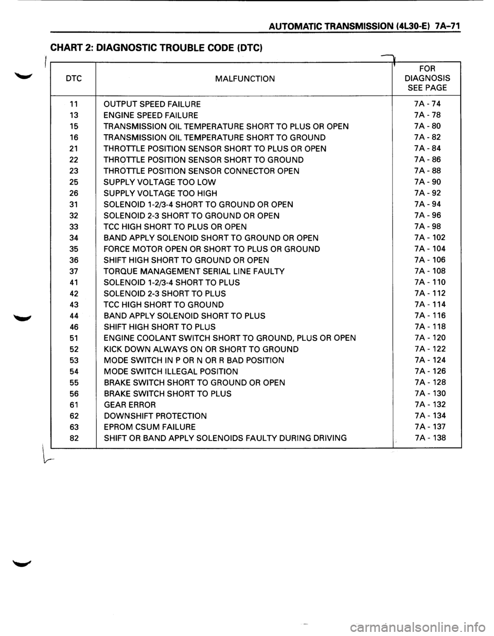
CHART 2: DIAGNOSTIC TROUBLE CODE (OTC)
I v
' FOR
DTC MALFUNCTION DIAGNOSIS
SEE PAGE
11 OUTPUT
SPEED FAILURE 7A -74
13 ENGINE SPEED FAILURE 7A -78
15 TRANSMISSION OIL TEMPERATURE SHORT TO PLUS OR OPEN 7A-80
16 TRANSMISSION OIL TEMPERATURE SHORT TO GROUND 7A-82
21 THROTTLE POSITION SENSOR SHORT TO PLUS OR OPEN 7A-84
22 THROTTLE POSITION SENSOR SHORT TO GROUND 7A-86
23 THROTTLE
POSITION SENSOR CONNECTOR OPEN 7A-88
25
SUPPLY VOLTAGE TOO LOW 7A-90
26 SUPPLY VOLTAGE TOO HIGH 7A-92
31 SOLENOID 1-2/3-4 SHORT TO GROUND OR OPEN 7A-94
32
SOLENOID 2-3 SHORT TO GROUND OR OPEN 7A-96
33 TCC
HIGH SHORT TO PLUS OR OPEN 7A-98
34
BAND APPLY SOLENOID SHORT TO GROUND OR OPEN 7A-102
35 FORCE MOTOR OPEN OR SHORT TO PLUS OR GROUND 7A-104
36 SHIFT HIGH SHORT TO GROUND OR OPEN 7A-106
37 TORQUE MANAGEMENT SERIAL LINE FAULTY 7A-108
41 SOLENOID 1-2/3-4 SHORT TO PLUS 7A-110
42 SOLENOID 2-3 SHORT TO PLUS 7A-112
43 TCC HIGH SHORT TO GROUND 7A-114
44
BAND APPLY SOLENOID SHORT TO PLUS 7A-116
46 SHIFT HIGH SHORT TO PLUS 7A-118
51 ENGINE COOLANT SWITCH SHORT TO GROUND, PLUS OR OPEN 7A-120
52 KICK DOWN ALWAYS ON OR SHORT TO GROUND 7A-122
53 MODE SWITCH IN P OR N OR R BAD POSITION 7A-124
54
MODE SWITCH ILLEGAL POSITION 7A-126
55 BRAKE
SWITCH SHORT TO GROUND OR OPEN 7A-128
56 BRAKE
SWITCH
SHORT TO PLUS 7A-130
61 GEAR ERROR 7A-132
62 DOWNSHIFT PROTECTION 7A-134
63
EPROM CSUM FAILURE 7A-137
82 SHIFT OR BAND APPLY SOLENOIDS FAULTY DURING DRIVING 7A-138
Page 956 of 1928
7 A-84 AUTOMATIC TRANSMISSION (4L30-E)
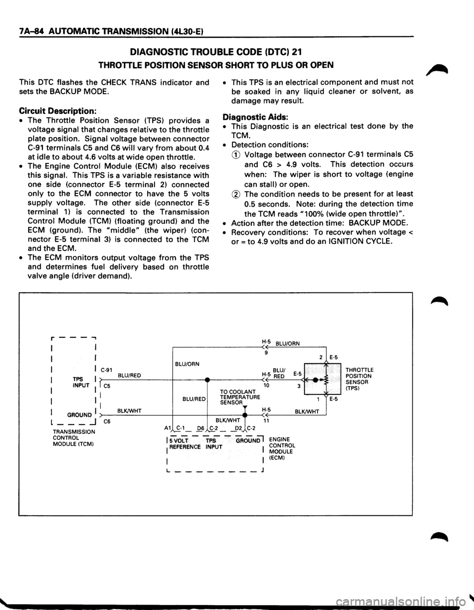
DIAGNOSTIC TROUBLE CODE (DTC) 21
THROTTLE POSITION SENSOR SHORT TO PLUS OR OPEN
This DTC flashes the CHECK TRANS indicator and
sets
the BACKUP MODE.
Circuit Description:
• The Throttle Position Sensor (TPS) provides a
voltage signal that changes relative to the throttle
plate position. Signal voltage between connector
C-91 terminals C5 and C6 will vary from about 0.4
at idle to about 4.6 volts at wide open throttle.
• The Engine Control Module (ECM) also receives
this signal. This TPS is a variable resistance with
one side (connector E-5 terminal 2) connected
only to the ECM connector to have the 5 volts
supply voltage. The other side (connector E-5
terminal 1) is connected to the Transmission
Control Module (TCM) (floating ground) and the
ECM (ground). The "middle" (the wiper) (con
nector E-5 terminal 3) is connected to the TCM
and
the ECM.
• The ECM monitors output voltage from the TPS
and determines fuel delivery based on throttle
valve angle (driver demand).
r---...,
I
I
I
I
I
I
TPS INPUT
I GROUND I L ___ _j
C-91
T C5
I
I
C6
BLU/ORN
BLU/RED
BLU/RED
BLK/WHT
• This TPS is an electrical component and must not
be soaked in any liquid cleaner or solvent, as
damage may result.
Diagnostic Aids:
• This Diagnostic is an electrical test done by the
TCM.
• Detection conditions:
CD Voltage between connector C-91 terminals C5
and C6 > 4.9 volts. This detection occurs
when: The wiper is short to voltage (engine
can
stall) or open.
@ The condition needs to be present for at least
0.5
seconds. Note: during the detection time
the TCM reads "100% (wide open throttle)".
• Action after the detection time: BACKUP MODE.
•
Recovery conditions: To recover when voltage <
or= to 4.9 volts and do an IGNITION CYCLE.
H-5 BLU/ORN
9
BLU/
H-5
RED E-5
-10 3 TO COOLANT TEMPERATURE
1 SENSOR H-5 BLK/WHT
BLK/WHT
11
2 E-5
E-5
THROTTLE POSITION
SENSOR
(TPS)
TRANSMISSION CONTROL MODULE
(TCM)
A1 S.-1_ 06 .,&_2 _ _!>2 C-2
lsvoLT-rps -aRouNDl ENGINE
I REFERENCE INPUT I CONTROL MODULE
I (ECM)
L--------J
Page 958 of 1928
7A-86 AUTOMATIC TRANSMISSION (4L30-E)
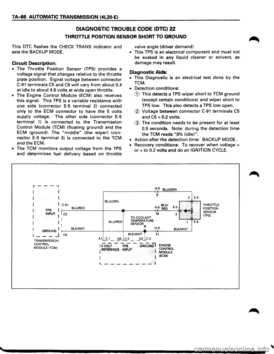
DIAGNOSTIC TROUBLE CODE (DTC) 22
THROTTLE POSITION SENSOR SHORT TO GROUND
This DTC flashes the CHECK TRANS indicator and
sets
the BACKUP MODE.
Circuit Description:
• The Throttle Position Sensor (TPS) provides a
voltage signal that changes relative to the throttle
plate position. Signal voltage between connector
C-91 terminals C5 and C6 will vary from about 0.4
at idle to about 4.6 volts at wide open throttle.
• The Engine Control Module (ECM) also receives
this signal. This TPS is a variable resistance with
one side (connector E-5 terminal 2) connected
only to the ECM connector to have the 5 volts
supply voltage. The other side (connector E-5
terminal 1) is connected to the Transmission
Control Module (TCM) (floating ground) and the
ECM (ground). The "middle" (the wiper) (con
nector E-5 terminal 3) is connected to the TCM
and the ECM.
• The TCM monitors output voltage from the TPS
and determines fuel delivery based on throttle
r---.,
I
I
I
I
I
I
TPS INPUT
I GROUND I L ___ .J
C-91
T C5
I
I
C6
BLU/ORN
BLU/RED
BLU/RED
BLK!WHT
valve angle (driver demand)
• This TPS is an electrical component and must not
be soaked in any liquid cleaner or solvent, as
damage may result.
Diagnostic Aids:
• This Diagnostic is an electrical test done by the
TCM.
• Detection conditions:
G) This detects a TPS wiper short to TCM ground
(except certain conditions) and wiper short to
TPS low. This also detects a TPS low open.
® Voltage between connector C-91 terminals C5
and C6 < 0.2 volts.
@ The condition needs to be present for at least
0.5
seconds. Note: during the detection time
the TCM reads "0% (idle)".
• Action after the detection time: BACKUP MODE.
•
Recovery conditions: To recover when voltage >
or= to 0.2 volts and do an IGNITION CYCLE.
H-5 BLU/ORN
9
BLU/
H- 5 RED E-5 _. 10 3 TO
COOLANT TEMPERATURE
1 SENSOR, H-5 BLK!WHT
BLK!WHT
11
2
:
E-5
E-5
THROTTLE POSITION
SENSOR
(TPS)
TRANSMISSION CONTROL MODULE
(TCM)
A1 S-1_ D6 ._£2-~2_, C-2
lsvo"Lr -"TP5 -"GRouNDl !REFERENCE INPUT 1
I I t_ ________ J
ENGINE
CONTROL MODULE
(ECM)
Page 960 of 1928
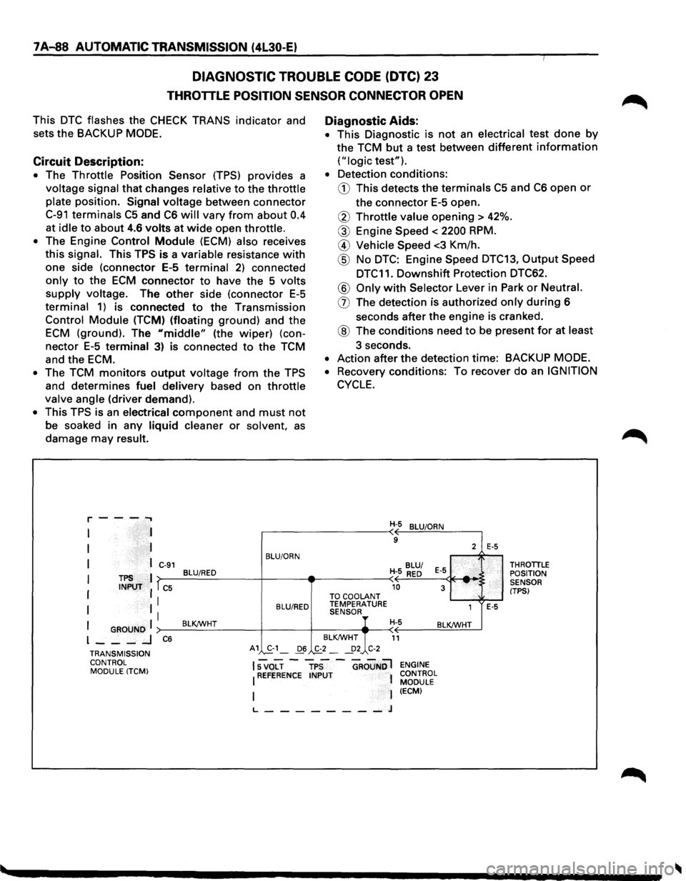
7A-88 AUTOMATIC TRANSMISSION (4l30-E)
DIAGNOSTIC TROUBLE CODE (DTC) 23
THROTTLE POSITION SENSOR CONNECTOR OPEN
This DTC flashes the CHECK TRANS indicator and
sets
the BACKUP MODE.
Circuit Description:
• The Throttle Position Sensor (TPS) provides a
voltage signal that changes relative to the throttle
plate position. Signal voltage between connector
C-91 terminals C5 and C6 will vary from about 0.4
at
idle to about 4.6 volts at wide open throttle.
• The Engine Control Module (ECM) also receives
this signal. This TPS is a variable resistance with
one side (connector E-5 terminal 2) connected
only to the ECM connector to have the 5 volts
supply voltage. The other side (connector E-5
terminal 1) is connected to the Transmission
Control Module (TCM) (floating ground) and the
ECM (ground). The "middle" (the wiper) (con
nector E-5 terminal 3) is connected to the TCM
and
the ECM.
• The TCM monitors output voltage from the TPS
and
determines fuel delivery based on throttle
valve angle (driver demand).
• This TPS is an electrical component and must not
be soaked in any liquid cleaner or solvent, as
damage may result.
r--...... ..,
I
I
I
TPS INPUT
I GROUND I l ___ _J
C-91
l C5
I
I
C6
BLU/ORN
BLU/RED
BLU/RED
BLKJWHT
A1 ,S.-1_ 06
Diagnostic Aids:
• This Diagnostic is not an electrical test done by
the TCM but a test between different information
("logic test").
• Detection conditions:
G) This detects the terminals C5 and C6 open or
the connector E-5 open.
® Throttle value opening > 42%.
® Engine Speed < 2200 RPM.
@ Vehicle Speed <3 Km/h.
@ No DTC: Engine Speed DTC13, Output Speed
DTC11.
Downshift Protection DTC62.
® Only with Selector Lever in Park or Neutral.
(]) The detection is authorized only during 6
seconds
after the engine is cranked.
® The conditions need to be present for at least
3 seconds.
• Action after the detection time: BACKUP MODE.
• Recovery conditions: To recover do an IGNITION
CYCLE.
TO COOLANT TEMPERATURE SENSOR
BLKJWHT
.,£2_ ~2 C-2
H-5 BLUIORN
9
2
BLU/
H- 5
RED E-5
10 3 .... ,'
1
H-5 BLKJWHT
11
E-5
E-5
THROTILE
POSITION
SENSOR
(TPSI
TRANSMISSION CONTROL MODULE (TCM)
15 VOLT -TPS -GROuNOl ENGINE
I REFERENCE INPUT 1 CONTROL l MODULE I (ECM)
L--------J