coolant temperature ISUZU TROOPER 1995 Repair Manual
[x] Cancel search | Manufacturer: ISUZU, Model Year: 1995, Model line: TROOPER, Model: ISUZU TROOPER 1995Pages: 1928
Page 800 of 1928
6E2-1 04 DRIVEABILITV AND EMISSIONS
Engine Coolant Temperature (ECT) Sensor
A "Scan tool" displays engine temperature in degrees
centigrade. After engine is started, the temperature
should rise steadily to about 90°C then stabilize when
thermostat opens. If the engine has not been run for
several hours (overnight), the engine coolant
temperature (ECT) and intake air temperature (IAT)
readings should be close to each other. A fault in the
ECT sensor circuit should set a diagnostic trouble code
(DTC) 14. The DTC charts also contain a chart to check
for sensor resistance values relative to temperature.
Intake Air Temperature (IAT) Sensor
A "Scan tool" displays temperature of the air entering
the engine and
should read close to ambient air
temperature when engine
is cold, and rise as under
hood temperature increases.
If the engine has not
been run for several hours (overnight), the IAT sensor
temperature and
ECT readings should be close to each
other. A
failure in the IAT sensor circuit should set a
DTC 23. The DTC charts also contain a chart to check
for sensor resistance values relative to temperature.
Heated Oxygen Sensor (H02S)
The "Scan tool" has several positions that will indicate
the state
of the exhaust gases, Oxygen voltage,
integrator, and block learn. See "Scan tool" position
information in
"Introduction", "Driveability and
Emission," in this section.
A
problem in the oxygen sensor circuit, or fuel system,
should set a DTC 13 (open circuit), DTC 44 (lean
indication)/DTC 45 (rich indication). Refer to
applicable chart, if any of these DTC(s) were stored in
memory.
Throttle Position (TP) Sensor
A "Scan tool" displays throttle position in volts. On 3.2L
engine, Throttle position
(TP) sensor voltage should
read below 0.85 volts, with throttle closed and ignition
"ON", or at idle. Voltage should increase at a steady
rate
as throttle is moved toward wide open throttle.
The Engine
Control Module (ECM) has the ability to
auto-zero the TP sensor voltage if it is below about 0.85
volts. This means that any voltage less than 0.85 volts
will
be determined by the ECM to be 0% throttle.
Some
"Scan tools" have the ability to read the throttle
angle and should read 0%, when the throttle is closed.
A failure in the TP sensor or circuit should set a DTC 21.
Manifold Absolute Pressure (MAP) Sensor
"Scan tool" displays manifold pressure in volts. Low
pressure (high vacuum) reads a
low voltage, while a
high pressure
(low vacuum) reads a high voltage. A
failure in the Manifold Absolute Pressure (MAP) sensor
circuit
should set a DTC 33 and using the chart will find
the cause
of the problem. A DTC 33 may be set if a
rough or unstable
idle exists. CHART C-1 D can also be
used
to check MAP sensor.
Vehicle Speed Sensor (VSS)
A "Scan tool" reading should closely match with
speedometer reading with drive wheels turning. A
failure in the vehicle speed sensor circuit should set a
DTC 24.
AIR CONDITIONING (A/C) Request Signal
When air conditioning in "ON", the "Scan tool" should
indicate air conditioning "ON".
See
"Air Conditioning Compressor Clutch Control
System",
Section "6E2-C1 0" for A/C electrical system
diagnosis.
Power Steering Pressure (PSP) Switch
A "Scan tool" should read "OFF" normally, and "ON"
with high pressure. This reading may vary with
different "Scan tools". Refer to CHART C-1 E for power
steering pressure switch diagnosis.
Crankshaft Position (CKP) Reference Signal
The ignition control module sends a signal to the ECM,
which is used to calculate proper spark advance and
fuel delivery. A "Scan tool" will read this signal and is
displayed in revolution per minute.
See "Electronic
Ignition System",
Section "6E2-C-4" for more
information on the ignition system (ignition control).
Park/Neutral Position (PNP) Switch
A "Scan tool" should read park/neutral position when
in park, or neutral, and R-D, L, when in drive or
overdrive. This reading may vary with different makes
of tools. Refer to CHART C-1 A for park/neutral position
switch diagnosis.
Knock Sensor (KS)
A "Scan tool" will indicate when the knock sensor
module signals the ECM that knock is present. See
"Knock
Sensor System," Section "6E2-C5" for further
information on the knock sensor system.
ON-VEHICLE SERVICE
ENGINE CONTROL MODULE (ECM)
The ECM is programmed from the factory and has no replaceable calibration chip.
•
Page 801 of 1928
wcAUTION:
' • When replacing the production Engine Control
Module
(ECM) with a service ECM (controller),
it is important to transfer the broadcast
diagnostic
trouble code and production ECM
number to the service ECM label. Please do not
record on ECM cover. This will allow positive
identification
of ECM parts throughout the
service
life of the vehicle.
DRIVEABILITV AND EMISSIONS 6E2-1 05
\fCAUTION:
' • To prevent internal ECM damage, the ignition
must be
"OFF" when disconnecting or
reconnecting power
to ECM (for example;
battery cable, ECM pigtail, ECM fuse, jumper
cables etc.)
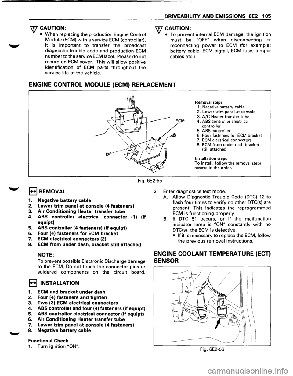
ENGINE CONTROL MODULE (ECM) REPLACEMENT
Removal steps 1. Negative battery cable 2. Lower trim panel at console
3. A/C Heater transfer tube ECM 4. ABS controller electrical
controller
5. ABS controller 6. Four fasteners for ECM bracket
7. ECM electrical connectors
8. ECM from under dash bracket still attached
Installation steps To install, follow the removal steps
reverse in the order.
Fig. 6E2-55
EJ REMOVAL
1. Negative battery cable
2. Lower trim panel at console (4 fasteners)
3. Air Conditioning Heater transfer tube
4. ABS controller electrical connector (1) (if
equipt)
5. ABS controller (4 fasteners) (if equipt)
6. Four (4) fasteners for ECM bracket
7. ECM
electrical connectors (2)
8. ECM from under dash, bracket
still attached
NOTE:
To prevent possible Electronic Discharge damage
to the ECM, Do not touch the connector pins or
soldered components on the circuit board.
I•+! INSTALLATION
1. ECM and bracket under dash
2. Four (4) fasteners and tighten
3. Two (2) ECM electrical connectors
4. ABS controller and four (4) fasteners (if equipt)
5. ABS controller electrical connector (if equipt)
6. Air Conditioning Heater transfer tube
7. Lower trim panel at console (4 fasteners)
8. Negative battery
cable
Functional
Check
1. Turn ignition "ON".
2. Enter diagnostics test mode.
A.
Allow Diagnostic Trouble Code (DTC) 12 to
flash four times to verify no other DTC(s) are
present. This indicates the reprogrammed
ECM is functioning properly.
B. If DTC 51 occurs, or if the malfunction
indicator lamp is "ON" constantly with no
DTC(s), the
ECM is defective.
• If it is necessary to replace the ECM, follow
the previous removal instructions.
ENGINE COOLANT TEMPERATURE (ECT)
SENSOR
Fig. 6E2-56
Page 802 of 1928
6E2-1 06 DRIVEABILITV AND EMISSIONS
1••1 REMOVAL
\f7 CAUTION:
Y/ Care must be taken when handling Engine
Coolant Temperature (ECT) sensor. Damage to
ECT sensor will affect proper operation of the fuel
injection system.
Preparation: • Negative battery cable.
•
Drain engine coolant system.
1. Inlet manifold assembly
• Refer to "Fuel metering system" section "6E2-
C2"
for removal procedure.
2. Electrical connector
3. ECT sensor
• Remove from rear of engine coolant transfer
tube.
I••IINSTALLATION
3. ECT sensor
• Apply sealer or equivalent to threads only.
•
Tighten the ECT sensor to the specified torque
~~~ Torque N·m (lb·ft) I 30 (22)
2. ECT sensor connector
1. Intake manifold assembly
• Refer to "Fuel metering system" section "6E2-
C2" for installation.
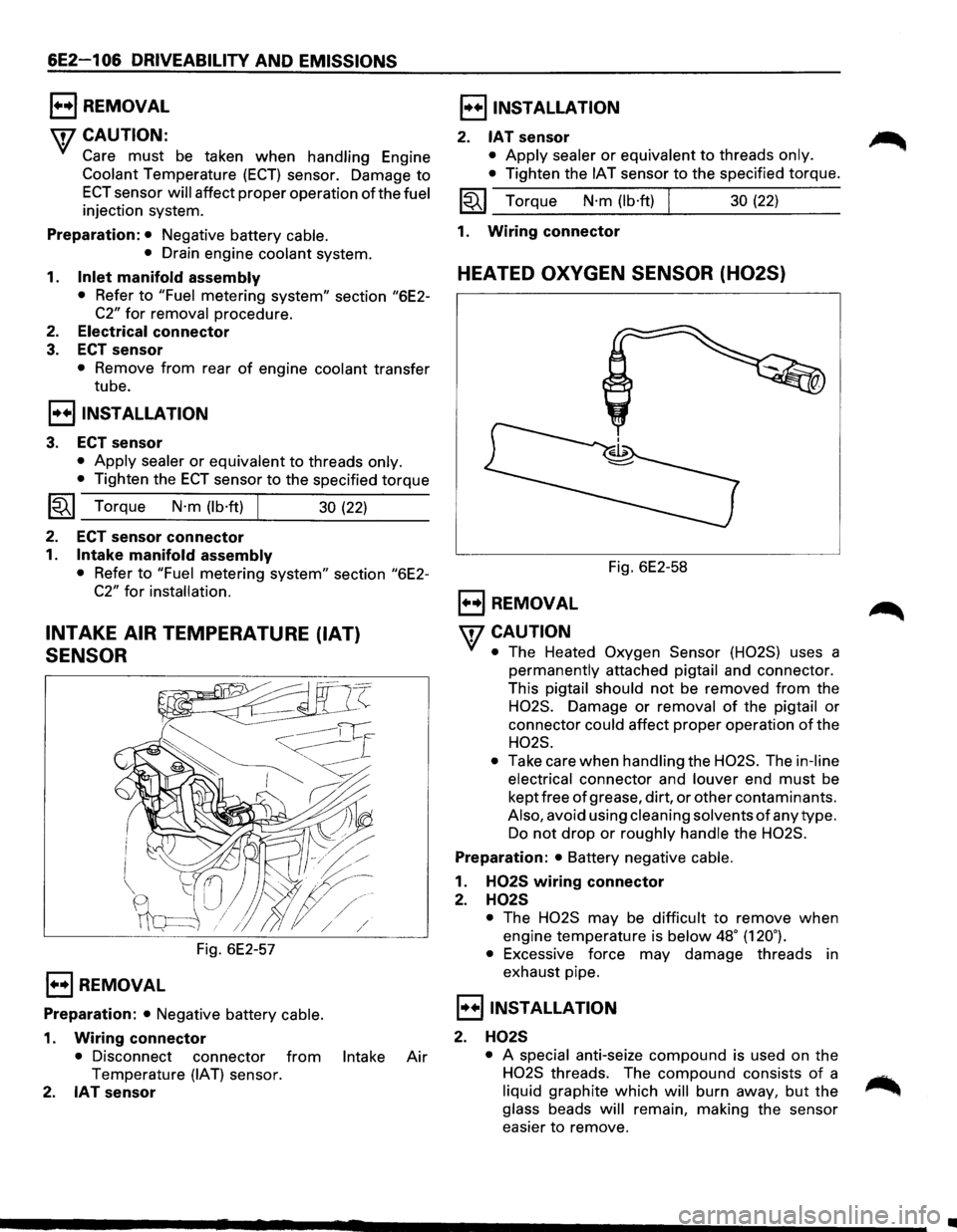
INTAKE AIR TEMPERATURE (IAT)
SENSOR
Fig. 6E2-57
1••1 REMOVAL
Preparation: • Negative battery cable.
1. Wiring connector
• Disconnect connector from Intake Air
Temperature (IAT) sensor.
2. IAT sensor
I••IINSTALLATION
2. IAT sensor
• Apply sealer or equivalent to threads only.
•
Tighten the IAT sensor to the specified torque.
~~~ Torque N·m (lb·ft) 30 (22)
1. Wiring
connector
HEATED OXYGEN SENSOR (H02S)
Fig. 6E2-58
1••1 REMOVAL
'fCAUTION
• The Heated Oxygen Sensor (H02S) uses a
permanently attached pigtail and connector.
This
pigtail should not be removed from the
H02S. Damage or removal of the pigtail or
connector
could affect proper operation of the
H02S.
•
Take care when handling the H02S. The in-line
electrical
connector and louver end must be
kept free
of grease, dirt, or other contaminants.
Also, avoid using cleaning solvents of any type.
Do not drop or roughly handle the H02S.
Preparation: • Battery negative cable.
1. H02S wiring connector
2. H02S
• The H02S may be difficult to remove when
engine temperature is
below 48• (120.).
•
Excessive force may damage threads in
exhaust pipe.
I••IINSTALLATION
2. H02S
• A special anti-seize compound is used on the
H02S threads. The compound consists of a
liquid graphite which will burn away, but the
glass beads will remain, making the sensor
easier
to remove.
•
Page 813 of 1928
MODES OF OPERATION
The Engine Control Module (ECM) uses voltage inputs
from several sensors to determine how much fuel to
give the engine. The fuel is delivered under one of
several conditions, called "modes". All the modes are
controlled by the ECM and are described below.
Starting Mode
When the ignition is first turned "ON", the ECM turns
"ON" the fuel pump relay for two seconds, and the fuel
pump builds up pressure. The ECM also checks the
Engine
Coolant Temperature (ECT) sensor and the
Throttle Position Sensor, and the determines the
proper
air/fuel ratio for starting. This ranges from 1.5:1
-36·c (-33.F) to 14.7:1, at 94•c (201.F) ECT.
The ECM controls the amount of fuel delivered in the
starting mode by changing
how long the injector is
turned
"ON" and "OFF". The is done by "Pulsing" the
injectors
for very short times.
Clear Flood Mode
If the engine floods, it may be cleared by pushing the
accelerator pedal down all the way. The ECM then will
fixed air/fuel ratio 16.5:1. The ECM holds this injector
rate
as long as the throttle stays wide open. If the
throttle position becomes less than approximately
70%, the ECM returns to the starting mode.
Run Mode
The run mode has two conditions called "Open Loop"
and "Closed Loop"
"Open Loop"
When the engine is first started, and it is above 500
Rovolution Per Minute (rpm), the system goes into
"Open Loop" operation. IN "Open Loop," the ECM
ignores the signal from the heated oxygen sensor
(H02S), and calculates the air/fuel ratio based on
inputs
from the ECT sensor and manifold absolute
pressure sensors.
The system stays in
"Open Loop" until the following
conditions are met:
1. The H02S has varying voltage output, showing
that
it is hot enough to operate properly. (This
depends on temperature.)
2. The ECT sensor is above a specified temperature.
3. A specific amount of time has elapsed after
starting the engine.
"Closed Loop"
The specific values for the above conditions vary with
different engines, and are stored in the ECM. When
these conditions are met, the system goes into
"Closed
Loop"
operation. In "Closed Loop", the ECM calculates
the air/fuel ratio (injector on-time) based on the signal
from the H02S. This allows the air/fuel ratio to stay
very close to 14.7:1.
DRIVEABILITV AND EMISSIONS 6E2-117
Acceleration Mode
The ECM responds to rapid changes in throttle position
and air
flow, and provides extra fuel.
Deceleration Mode
The ECM responds to changes in throttle position and
air
flow, and reduces the amount of fuel. When
deceleration is very fast, the ECM can cut off fuel
completely
for short periods.
Battery Positive Voltage Correction Mode
When battery positive voltage is low, the ECM can
compensate
for a weak spark delivered by the ignition
control module by:
• Increasing injector pulse width.
• Increasing the idle rpm.
• Increasing ignition dwell time.
Fuel Cutoff Mode
The fuel injectors are shut "OFF" if engine speed
"exceed" 6880 rpm (DOHC) or6800 rpm (SOHC). This is
to prevent damage to engine. When engine speed is
below 6880 rpm (DOHC) or 6800 rpm (SOHC), the fuel
injectors are again pulsed at a normal mode.
Page 816 of 1928
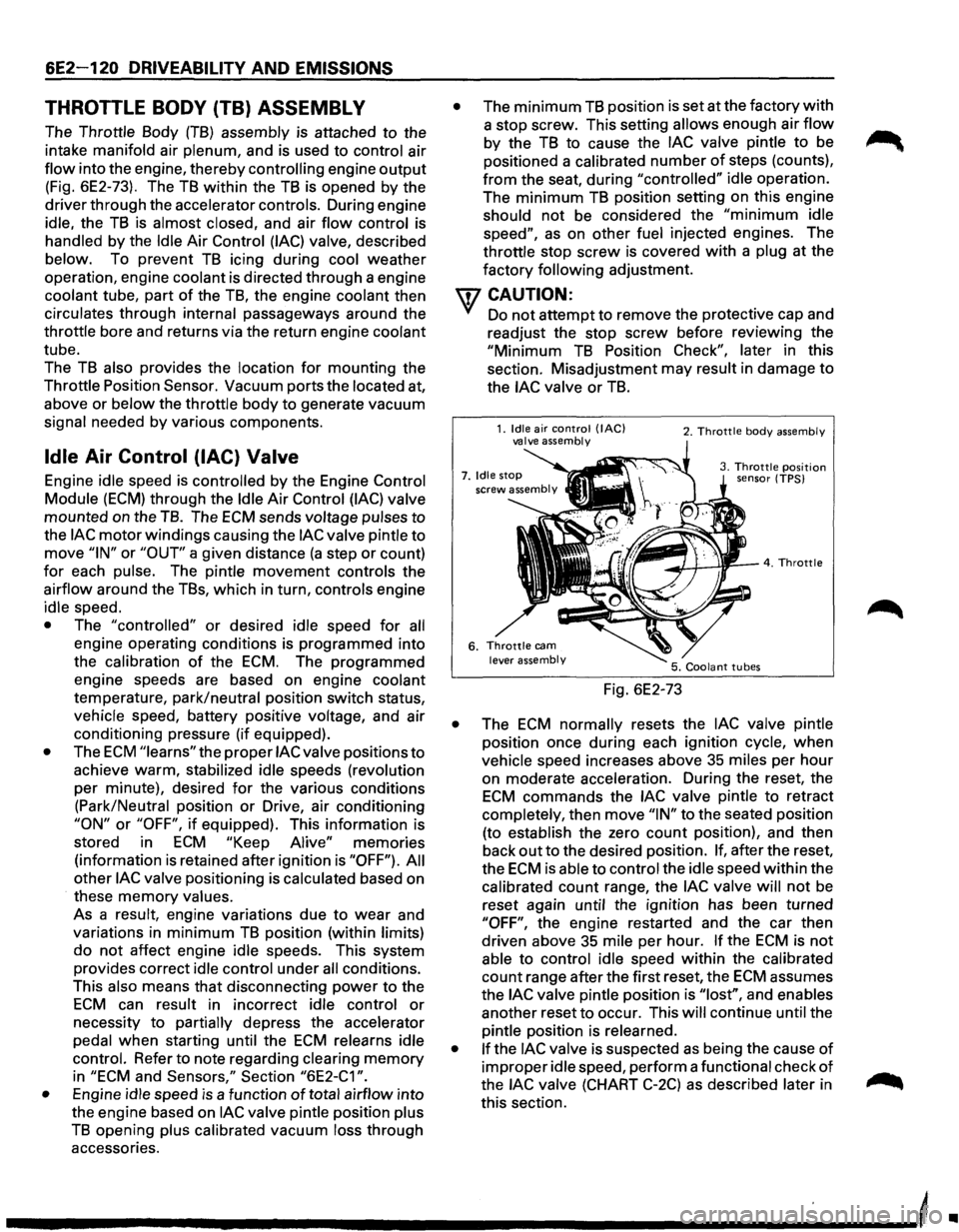
6E2 120 DRIVEABILITY AND EMISSIONS
THROTTLE BODY (TB) ASSEMBLY
The Throttle Body (TB) assembly is attached to the
intake manifold air
plenum, and is used to control air
flow into the engine, thereby controlling engine output
(Fig. 6E2-73). The TB within the TB is opened by the
driver through the accelerator controls. During engine
idle, the
TB is almost closed, and air flow control is
handled by the Idle Air Control (lAC) valve, described
below. To prevent
TB icing during cool weather
operation, engine
coolant is directed through a engine
coolant tube, part
of the TB, the engine coolant then
circulates through internal passageways around the
throttle bore and returns via the return engine coolant
tube.
The
TB also provides the location for mounting the
Throttle Position
Sensor. Vacuum ports the located at,
above or
below the throttle body to generate vacuum
signal needed
by various components.
Idle Air Control (lAC) Valve
Engine idle speed is controlled by the Engine Control
Module (ECM) through the Idle Air Control (lAC) valve
mounted on the
TB. The ECM sends voltage pulses to
the lAC motor windings causing the lAC valve pintle to
move "IN" or "OUT" a given distance (a step or count)
for each pulse. The pintle movement controls the
airflow around the TBs, which in turn, controls engine
idle speed.
• The "controlled" or desired idle speed for all
engine operating conditions is programmed into
the
calibration of the ECM. The programmed
engine speeds are based on engine coolant
temperature, park/neutral position switch status,
vehicle speed, battery positive voltage, and air
conditioning pressure (if equipped).
• The ECM "learns" the proper lAC valve positions to
achieve warm, stabilized idle speeds (revolution
per minute), desired
for the various conditions
(Park/Neutral position
or Drive, air conditioning
"ON" or "OFF", if equipped). This information is
stored in
ECM "Keep Alive" memories
(information
is retained after ignition is "OFF"). All
other lAC valve positioning is calculated based on
these
memory values.
As a
result, engine variations due to wear and
variations in
minimum TB position (within limits)
do not affect engine idle speeds. This system
provides correct idle control under
all conditions.
This also means
that disconnecting power to the
ECM can result in incorrect idle control or
necessity to partially depress the accelerator
pedal
when starting until the ECM relearns idle
control. Refer to note regarding clearing
memory
in "ECM and Sensors," Section "6E2-C1 ".
•
Engine idle speed is a function of total airflow into
the engine based on
lAC valve pintle position plus
TB opening plus calibrated vacuum loss through
accessories.
• The minimum TB position is set at the factory with
a stop screw. This setting allows enough air flow
by the TB to cause the lAC valve pintle to be
positioned a calibrated
number of steps (counts),
from the seat, during "controlled" idle operation.
The
minimum TB position setting on this engine
should not be considered the
"minimum idle
speed", as on other fuel injected engines. The
throttle stop
screw is covered with a plug at the
factory
following adjustment.
U7 CAUTION:
VI Do not attempt to remove the protective cap and
readjust the stop screw before
reviewi~g t~e
"Minimum TB Position Check", later m th1s
section. Misadjustment may result in damage to
the lAC valve or TB.
Fig. 6E2-73
2. Throttle body assembly
3. Throttle position sensor (TPS)
• The ECM normally resets the lAC valve pintle
position once during each ignition cycle,
when
vehicle speed increases above 35 miles per hour
on moderate acceleration. During the reset, the
ECM commands the lAC valve pintle to retract
completely, then move
"IN" to the seated position
(to establish the zero
count position), and then
back
out to the desired position. If, after the reset,
the
ECM is able to control the idle speed within the
calibrated count range, the
lAC valve will not be
reset again until the ignition has been turned
"OFF", the engine restarted and the car then
driven above 35 mile per hour.
If the ECM is not
able to control idle speed within the calibrated
count range after the first reset, the
ECM assumes
the
lAC valve pintle position is "lost", and enables
another reset
to occur. This will continue until the
pintle position is relearned.
• If the lAC valve is suspected as being the cause of
improper idle speed, perform a functional check of
the lAC valve (CHART C-2C) as described later in
this section.
-----------------------------'
•
Page 832 of 1928
6E2-136 DRIVEABILITY AND EMISSIONS
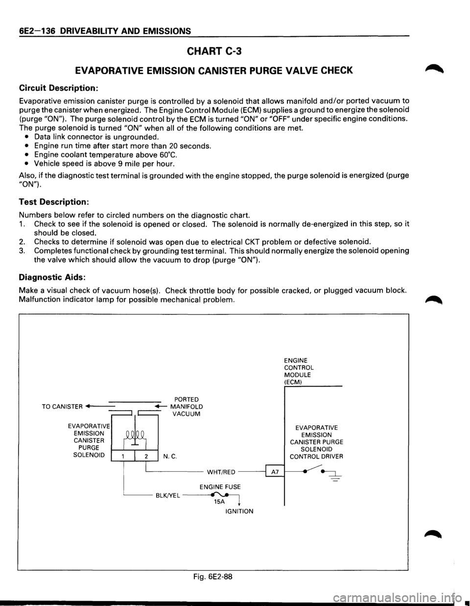
CHART C-3
EVAPORATIVE EMISSION CANISTER PURGE VALVE CHECK
Circuit Description:
Evaporative emission canister purge is controlled by a solenoid that allows manifold and/or ported vacuum to
purge the canister when energized. The Engine Control Module (ECM) supplies a ground to energize the solenoid
(purge "ON"). The purge solenoid control by the ECM is turned "ON" or "OFF" under specific engine conditions.
The purge
solenoid is turned "ON" when all of the following conditions are met.
• Data link connector is ungrounded.
• Engine run time after start more than 20 seconds.
• Engine coolant temperature above 60°C.
• Vehicle speed is above 9 mile per hour.
Also, if the diagnostic test terminal is grounded with the engine stopped, the purge solenoid is energized (purge
"ON").
Test Description:
Numbers below refer to circled numbers on the diagnostic chart.
1. Check to see if the solenoid is opened or closed. The solenoid is normally de-energized in this step, so it
should be closed.
2. Checks to determine if solenoid was open due to electrical CKT problem or defective solenoid.
3. Completes functional check by grounding test terminal. This should normally energize the solenoid opening
the
valve which should allow the vacuum to drop (purge "ON").
Diagnostic Aids:
Make a visual check of vacuum hose(s). Check throttle body for possible cracked, or plugged vacuum block.
Malfunction
indicator lamp for possible mechanical problem.
EVAPORATIVE
EMISSION CANISTER
PURGE SOLENOID N.C.
L__ _____ WHT/RED -----;
ENGINE FUSE
BLKJYEL~ 15A ~
IGNITION
Fig. 6E2-88
ENGINE
CONTROL
MODULE (ECM)
EVAPORATIVE EMISSION
CANISTER
PURGE SOLENOID
CONTROL DRIVER
•
Page 835 of 1928
RESULTS OF INCORRECT OPERATION
An open or ground in the Ignition Control (I C) or bypass
circuits
will set a Diagnostic Trouble Code (DTC) 42 and
cause the engine
to run on the Ignition Control Module
(ICM)
timing.
The Engine
Control Module (ECM) uses information
from the Intake Air Temperature (IAT) and engine
coolant sensors in addition to revolution per minute
(rpm) to
calculate spark advance as follows:
• Cold
engine -more spark advance.
• Engine under minimum load based on rpm and
low amount of air flow = more spark advance.
• Hot engine = less spark advance.
• Engine under heavy load based on rpm and high
air
flow = less spark advance.
HOW DIAGNOSTIC TROUBLE CODE (DTC)
42 IS DETERMINED
When the system is running on the ICM, that is, no
voltage on the bypass line, the ICM grounds (GND) the
IC signal. The ECM expects to see no voltage on the IC
line during this condition.lf it sees a voltage, it sets DTC
42 and will not go into the IC mode.
DRIVEABILITY AND EMISSIONS 6E2-139
When the rpm for IC is reached (about 400 rpm) the
ECM applies 5 volts to the bypass line and the IC should
no longer be grounded in the ICM so the IC voltage
should
be varying.
An open in the
IC circuit while running, will result in the
engine continuing to run, but in a back-up
ig~it~on
timing mode (module timing) at a calculated t1mmg
value
and the malfunction indicator lamp will not be
"ON".
If
the IC circuit is shorted to GND, the "Check Engine"
malfunction
indicator lamp will be turned "ON", and a
DTC 42 will be set and the engine will operate in
module timing. Either condition may cause poor
performance and reduced
fuel economy.
If the bypass line is open or GND, the ICM will not
switch to IC mode so the IC voltage will be low and DTC
42 will be set.
If the IC line is grounded, the ICM will switch to IC, but
because the line isGNDtherewill be no ICsignai.A DTC
42 will be set.
DIAGNOSIS
If the engine cranks but will not run, CHART A-3 will be
used to determine if the Electronic Ignition (EI) system
is the cause
of the problem or if it is another part of the
fuel injection system.
If DTC 42 is set, that DTC chart should be used for
diagnosis. If no DTC is set and the ignition system is
suspected, use
CHART C4-D ("EI" Misfire) for
diagnosis.
DIAGNOSTIC TROUBLE CODE (DTC) 12
DTC 12 is used during the on-board diagnostic system
check procedure to test the
DTC display ability of the
ECM. This diagnostic trouble code indicates that the
ECM is not receiving the engine speed (REFERENCE)
signal. This occurs with the ignition key "ON" and the
engine not running.
The "reference"
signal also triggers the fuel injection
system.
Without the "reference" signal the engine
cannot run.
ON-VEHICLE SERVICE
ELECTRONIC IGNITION (EI) ASSEMBLY
1••1 REMOVE OR DISCONNECT
1. Negative battery cable
2. "EI" electrical connectors (3)
3. Spark plug wires. (Note wire positions to proper
coils) (6)
4. "EI" assembly to bracket bolts (3)
5. "EI" assembly from Intake Plenum.
1••1 INSTALL OR CONNECT
1. "EI" assembly bracket to Intake Plenum
Tighten bolts to 25 N·m (19 lb·ft)
2. Spark plug wires to correct spark plugs
3. "EI" electrical connectors
4. Negative battery cable
Page 847 of 1928
DRIVEABILITY AND EMISSIONS 6E2-151
SECTION C-7
EXHAUST GAS RECIRCULATION (EGR) SYSTEM
CONTENTS
GENERAL DESCRIPTION ................. 6E2-151
Operation . . . . . . . . . . . . . . . . . . . . . . . . . . . 6E2-151
Exhaust Gas
Recirculation (EGR) Valve
Check . .
. . . . . . . . . . . . . . . . . . . . . . . . . . 6E2-152
Exhaust Gas
Recirculation (EGR)
Backpressure Transducer (BPT) Check 6E2-152
Exhaust Gas
Recirculation (EGR)
Vacuum Switch Valve (VSV) Solenoid
Check . .
. . . . . . . . . . . . . . . . . . . . . . . . . . 6E2-152
DIAGNOSIS ........................... 6E2-153
ON-VEHICLE SERVICE .................... 6E2-153
Exhaust Gas
Recirculation (EGR)
Manifold Passage ................... 6E2-153
Exhaust Gas
Recirculation (EGR)
Valve Replacement .................. 6E2-153
Exhaust
Gas Recirculation (EGR)
Backpressure Transducer (BPT)
Replacement ....................... 6E2-153
Exhaust Gas
Recirculation (EGR)
Vacuum Switch Valve (VSV) Replacement . 6E2-153
CHART C-7A Exhaust Gas
Recirculation (EGR)
System Check ...................... 6E2-154
GENERAL DESCRIPTION
The Exhaust Gas Recirculation (EGR) System controls
the formation of NOx (Oxides of Nitrogen) Emissions
by
recirculating the exhaust gases into the combustion
chamber. This is done through the intake
manifold.
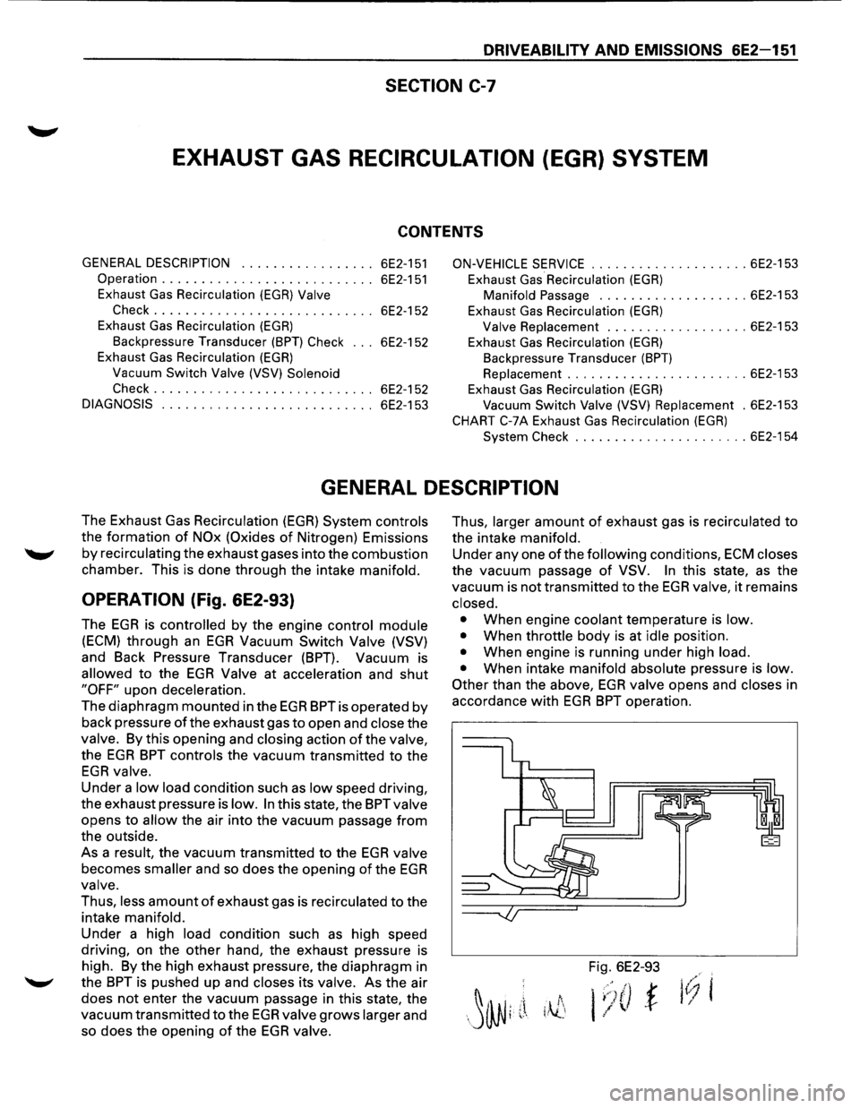
OPERATION (Fig. 6E2-93)
The EGR is controlled by the engine control module
(ECM) through an EGR Vacuum Switch Valve (VSV)
and Back Pressure Transducer (BPT). Vacuum is
allowed to the EGR Valve at acceleration and shut
"OFF" upon deceleration.
The diaphragm mounted in the EGR BPT is operated by
back pressure
of the exhaust gas to open and close the
valve. By this opening and closing action of the valve,
the EGR BPT controls the vacuum transmitted to the
EGR valve.
Under
a low load condition such as low speed driving,
the exhaust pressure is
low. In this state, the BPTvalve
opens to allow the air into the vacuum passage from
the outside.
As a
result, the vacuum transmitted to the EGR valve
becomes smaller and so does the opening of the EGR
valve.
Thus, less amount of exhaust gas is recirculated to the
intake
manifold.
Under
a high load condition such as high speed
driving, on the
other hand, the exhaust pressure is
high. By the high exhaust pressure, the diaphragm in
the
BPT is pushed up and closes its valve. As the air
does
not enter the vacuum passage in this state, the
vacuum transmitted
to the EGR valve grows larger and
so does the opening
of the EGR valve.
Thus, larger amount of exhaust gas is recirculated to
the intake manifold.
Under
any one ofthe following conditions, ECM closes
the vacuum passage of VSV. In this state, as the
vacuum is not transmitted
to the EGR valve, it remains
closed.
•
When engine coolant temperature is low.
•
When throttle body is at idle position.
• When engine is running under high load.
•
When intake manifold absolute pressure is low.
Other
than the above, EGR valve opens and closes in
accordance
with EGR BPT operation.
Fig. 6E2-93
i
.
,::·)I)' t
/
..f-l
Page 853 of 1928
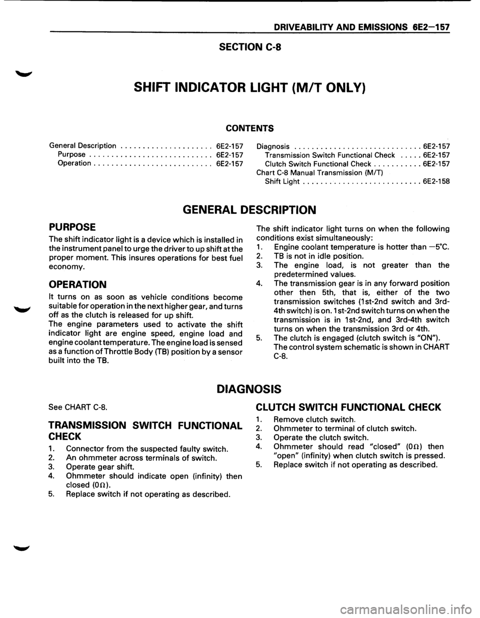
DRIVEABILITY AND EMISSIONS 6E2-157
SECTION C-8
SHIFT INDICATOR LIGHT (MIT ONLY)
CONTENTS
General Description . . . . . . . . . . . . . . . . . . . . . 6E2-157 Diagnosis ............................. 6E2-157
Purpose ............................ 6E2-157 Transmission Switch Functional Check ..... 6E2-157
Operation . . . . . . . . . . . . . . . . . . . . . . . . . . . 6E2-157 Clutch Switch Functional Check ........... 6E2-157
Chart C-8 Manual Transmission (M/T)
Shift Light ........................... 6E2-158
GENERAL DESCRIPTION
PURPOSE
The shift indicator light is a device which is installed in
the instrument
panel to urge the driver to up shiftatthe
proper moment. This insures operations for best fuel
economy.
OPERATION
It turns on as soon as vehicle conditions become
suitable for operation in the next higher gear, and turns
off as the clutch is released for up shift.
The engine parameters used
to activate the shift
indicator
light are engine speed, engine load and
engine
coolant temperature. The engine load is sensed
as a function of Throttle Body (TB) position by a sensor
built into the TB. The
shift indicator
light turns on when the following
conditions exist simultaneously:
1. Engine coolant temperature is hotter than -s·c.
2. TB is not in idle position.
3. The engine load, is not greater than the
predetermined
values.
4. The transmission gear is in any forward position
other then 5th, that is, either
of the two
transmission switches (1st-2nd switch and 3rd-
4th switch) is on. 1st-2nd switch turns on
when the
transmission is in 1st-2nd, and 3rd-4th switch
turns on when the transmission 3rd
or 4th.
5. The clutch is engaged (clutch switch is "ON").
The control system schematic is shown in CHART
C-8.
DIAGNOSIS
See CHART C-8.
TRANSMISSION SWITCH FUNCTIONAL
CHECK
1. Connector from the suspected faulty switch.
2. An ohmmeter across terminals of switch.
3. Operate gear shift.
4. Ohmmeter should indicate open (infinity) then
closed (00).
5. Replace switch if not operating as described.
CLUTCH SWITCH FUNCTIONAL CHECK
1. Remove clutch switch.
2. Ohmmeter to terminal of clutch switch.
3. Operate the clutch switch.
4. Ohmmeter should read "closed" (00) then
"open" (infinity) when clutch switch is pressed.
5. Replace switch if not operating as described.
Page 854 of 1928
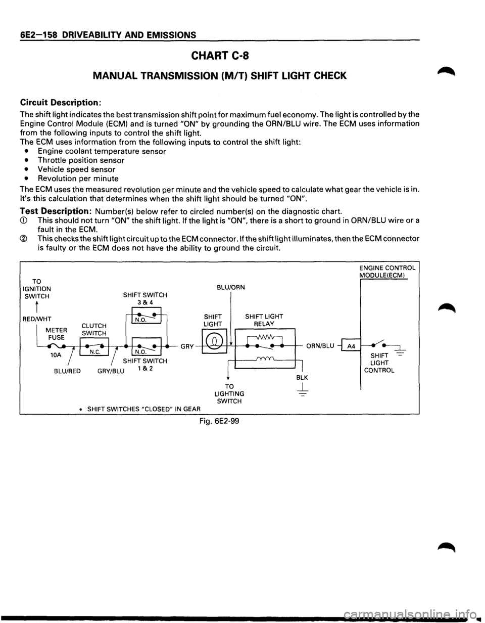
6E2-158 DRIVEABILITV AND EMISSIONS
CHART C-8
MANUAL TRANSMISSION (M/T) SHIFT LIGHT CHECK
Circuit Description:
The shift light indicates the best transmission shift point for maximum fuel economy. The light is controlled by the
Engine Control Module
(ECM) and is turned "ON" by grounding the ORN/BLU wire. The ECM uses information
from the following inputs to control the shift light.
The
ECM uses information from the following inputs to control the shift light:
• Engine coolant temperature sensor
• Throttle position sensor
• Vehicle speed sensor
• Revolution per minute
The
ECM uses the measured revolution per minute and the vehicle speed to calculate what gear the vehicle is in.
It's this calculation that determines when the shift light should be turned "ON".
Test Description: Number(s) below refer to circled number(s) on the diagnostic chart.
ECM.
® This checks the shift light circuit up to the ECM connector .If the shift light illuminates, then the ECM connector
is faulty
or the ECM does not have the ability to ground the circuit.
TO
IGNITION SWITCH
t
BLU/RED GRY/BLU
•
SHIFT SWITCHES #CLOSED" IN GEAR
BLU/ORN
SHIFT SHIFT LIGHT
LIGHT
RELAY
TO
LIGHTING SWITCH
Fig. 6E2-99
ENGINE CONTROL
MODULE(ECMl
SHIFT
LIGHT
CONTROL