coolant temperature ISUZU TROOPER 1995 Service Manual
[x] Cancel search | Manufacturer: ISUZU, Model Year: 1995, Model line: TROOPER, Model: ISUZU TROOPER 1995Pages: 1928
Page 758 of 1928
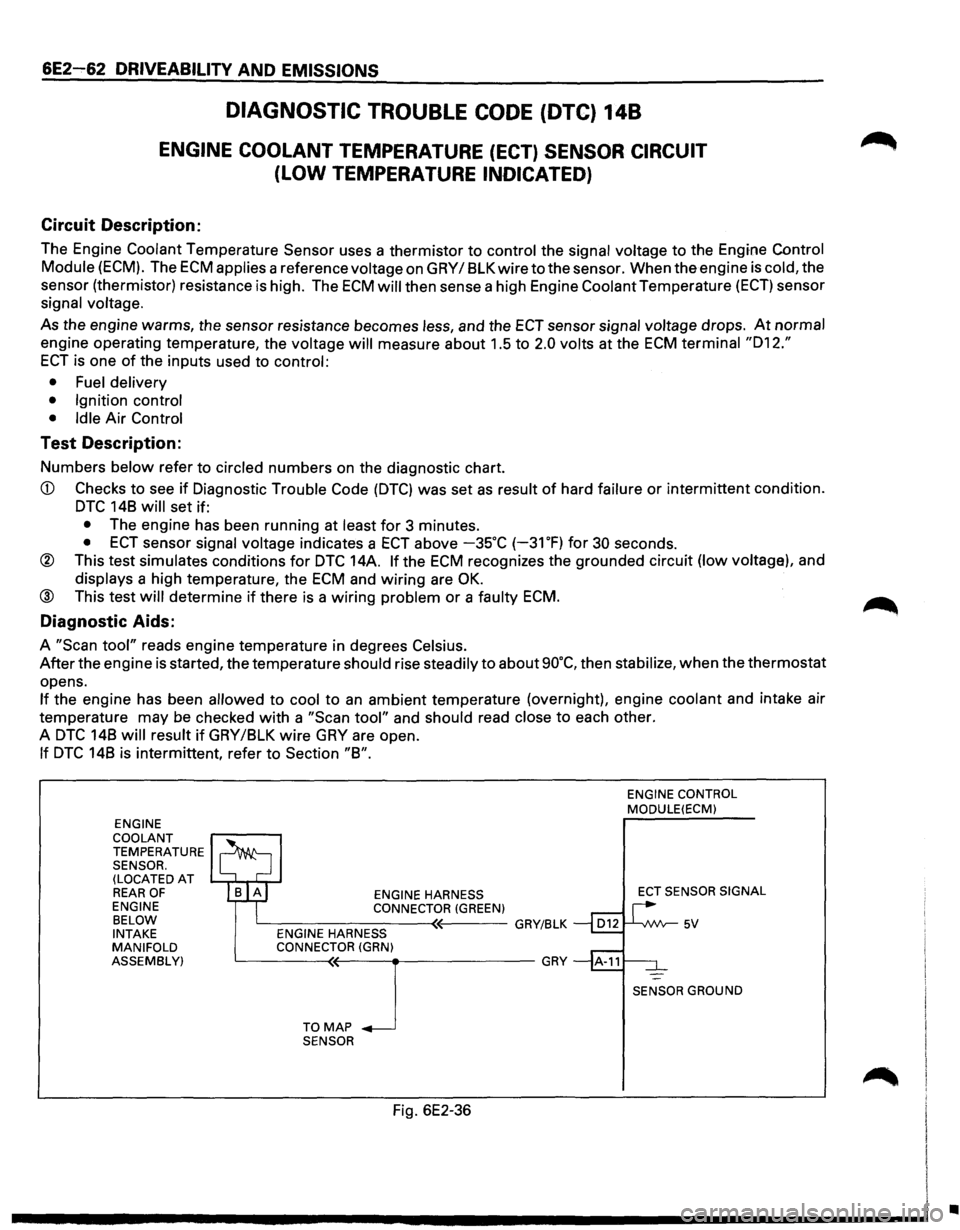
6E2~62 DRIVEABILITY AND EMISSIONS
DIAGNOSTIC TROUBLE CODE (DTC) 148
ENGINE COOLANT TEMPERATURE (ECT) SENSOR CIRCUIT
(LOW TEMPERATURE INDICATED)
Circuit Description:
The Engine Coolant Temperature Sensor uses a thermistor to control the signal voltage to the Engine Control
Module (ECM). The ECM applies a reference voltage on GRY I 8LK wire to the sensor. When the engine is cold, the
sensor (thermistor) resistance
is high. The ECM will then sense a high Engine Coolant Temperature (ECT) sensor
signal
voltage.
As the engine warms, the sensor resistance becomes less, and the ECT sensor signal voltage drops. At normal
engine operating temperature, the voltage will measure about 1.5 to 2.0 volts at the ECM terminal "012."
ECT is one of the inputs used to control:
• Fuel delivery
• Ignition control
• Idle
Air Control
Test Description:
Numbers below refer to circled numbers on the diagnostic chart.
CD Checks to see if Diagnostic Trouble Code (DTC) was set as result of hard failure or intermittent condition.
DTC 148 will set if:
• The engine has been running at least for 3 minutes.
• ECT sensor signal voltage indicates a ECT above -35°C (-31 OF) for 30 seconds.
® This test simulates conditions for DTC 14A. If the ECM recognizes the grounded circuit (low voltage), and
displays a high temperature, the ECM and wiring are OK.
@ This test will determine if there is a wiring problem or a faulty ECM.
Diagnostic Aids:
A "Scan tool" reads engine temperature in degrees Celsius.
After the engine is started, the temperature should rise steadily to about 90°C, then stabilize, when the thermostat
opens.
If the engine has been allowed to cool to an ambient temperature (overnight), engine coolant and intake air
temperature may be checked
with a "Scan tool" and should read close to each other.
A
DTC 148 will result if GRY/8LK wire GRY are open.
If DTC 148 is intermittent, refer to Section "8".
ENGINE
COOLANT
TEMPERATURE SENSOR.
(LOCATED AT REAR OF ENGINE
BELOW
INTAKE
MANIFOLD
ASSEMBLY) ENGINE
HARNESS
CONNECTOR (GREEN) c__---------<~'----GRY/BLK ENGINE HARNESS
CONNECTOR (GRN)
~---T-0--<'M<(--A-P_J ___________ GRY
SENSOR
Fig. 6E2-36
ENGINE CONTROL MODULE(ECM)
ECT
SENSOR SIGNAL
SENSOR GROUND
•
Page 759 of 1928
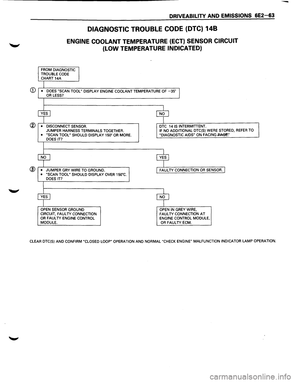
DRIVEABILITV AND EMISSIONS 6E2-63
DIAGNOSTIC TROUBLE CODE (DTC) 148
ENGINE COOLANT TEMPERATURE (ECT) SENSOR CIRCUIT
(LOW TEMPERATURE INDICATED)
FROM DIAGNOSTIC
TROUBLE CODE CHART 14A
I • DOES "SCAN TOOL" DISPLAY ENGINE COOLANT TEMPERATURE OF -35"l OR LESS?
I
~ $
• DISCONNECT SENSOR. DTC 14 IS INTERMITTENT. JUMPER
HARNESS TERMINALS TOGETHER. IF NO ADDITIONAL DTC(S) WERE STORED, REFER TO
• "SCAN TOOL" SHOULD DISPLAY 150" OR MORE. "DIAGNOSTIC AIDS" ON FACING~ DOES IT?
I
$ c$
• JUMPER
GRY WIRE TO GROUND. FAUL TV CONNECTION OR SENSOR. I • "SCAN TOOL" SHOULD DISPLAY OVER 150"C.
DOES IT?
I
~ $
OPEN SENSOR GROUND OPEN IN GREY WIRE,
CIRCUIT, FAUL TV CONNECTION FAUL TV CONNECTION AT OR FAUL TV ENGINE CONTROL ENGINE CONTROL MODULE,
MODULE. OR FAUL TV ECM.
CLEAR DTC(S)
AND CONFIRM "CLOSED LOOP" OPERATION AND NORMAL "CHECK ENGINE" MALFUNCTION INDICATOR LAMP OPERATION.
Page 764 of 1928
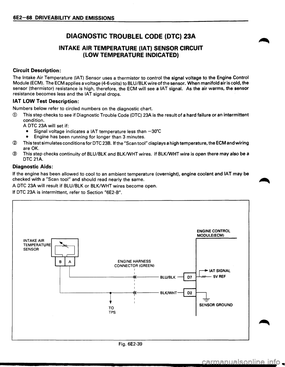
6E2-68 DRIVEABILITV AND EMISSIONS
DIAGNOSTIC TROUBLEL CODE (DTC) 23A
INTAKE AIR TEMPERATURE {IAT) SENSOR CIRCUIT
(LOW TEMPERATURE INDICATED)
Circuit Description:
The Intake Air Temperature (IAT) Sensor uses a thermistor to control the signal voltage to the Engine Control
Module
(ECM). The ECM applies a voltage (4-6volts) to BLU/BLK wire of the sensor. When manifold air is cold, the
sensor (thermistor) resistance is high, therefore, the
ECM will see a IAT signal. As the air warms, the sensor
resistance becomes
less and the IAT signal drops.
IAT LOW Test Description:
Numbers below refer to circled numbers on the diagnostic chart.
CD This step checks to see if Diagnostic Trouble Code (DTC) 23A is the result of a hard failure or an intermittent
condition.
A
DTC 23A will set if:
• Signal voltage indicates a IAT temperature less than -30"C
• Engine has been running for longer than 3 minutes.
® This test simulates conditions for DTC 238. If the "Scan tool" displays a high temperature, the ECM and wiring
are OK.
@ This step checks continuity of BLU/BLK and BLK/WHT wires. If BLK/WHT wire is open there may also be a
DTC 21A.
Diagnostic Aids:
If the engine has been allowed to cool to an ambient temperature (overnight), engine coolant and IAT may be
checked
with a "Scan tool" and should read nearly the same. ~
A DTC 23A will result if BLU/BLK or BLK/WHT wires become open.
If DTC 23A is intermittent, refer to Section "6E2-B".
INTAKE AIR TEMPERATURE SENSOR
ENGINE HARNESS
CONNECTOR
(GREEN) I
L-----------«----BLU/BLK
TO TPS
Fig. 6E2-39
ENGINE CONTROL
MODULE(ECM)
IATSIGNAL
1--'--IW'--5V REF
SENSOR GROUND
Page 766 of 1928
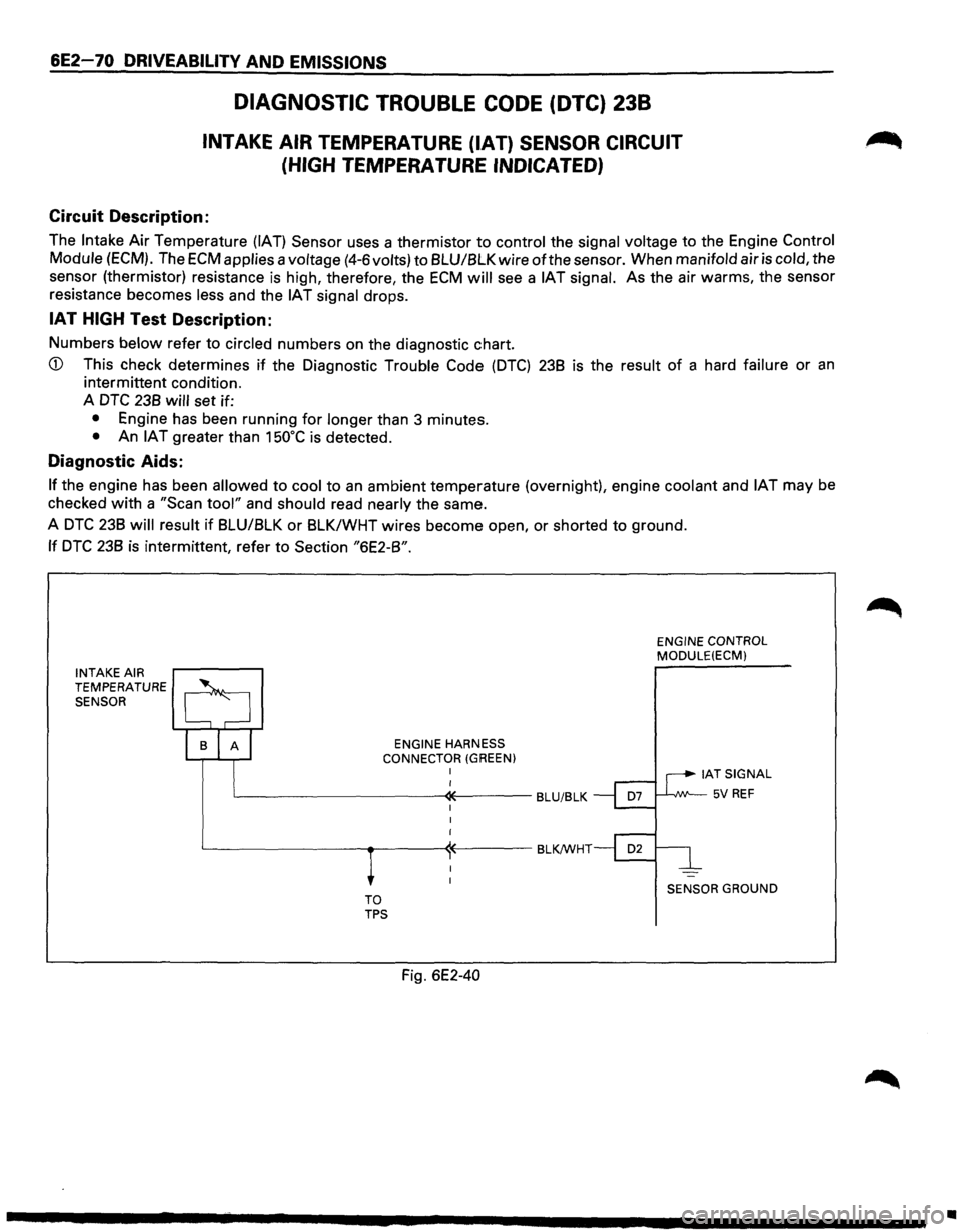
6E2-70 DRIVEABILITV AND EMISSIONS
DIAGNOSTIC TROUBLE CODE (DTC) 238
INTAKE AIR TEMPERATURE (IAT) SENSOR CIRCUIT
(HIGH
TEMPERATURE INDICATED)
Circuit Description:
The Intake Air Temperature (IAT) Sensor uses a thermistor to control the signal voltage to the Engine Control
Module (ECM). The
ECM applies a voltage (4-6 volts) to 8LU/8LK wire ofthe sensor. When manifold air is cold, the
sensor (thermistor) resistance is high, therefore, the
ECM will see a IAT signal. As the air warms, the sensor
resistance becomes less and the
IAT signal drops.
IAT HIGH Test Description:
Numbers below refer to circled numbers on the diagnostic chart.
CD This check determines if the Diagnostic Trouble Code (DTC) 238 is the result of a hard failure or an
intermittent condition.
A
DTC 238 will set if:
• Engine has been running for longer than 3 minutes.
• An IAT greater than 150°C is detected.
Diagnostic Aids:
If the engine has been allowed to cool to an ambient temperature (overnight), engine coolant and IAT may be
checked with a "Scan tool" and should read nearly the same.
A
DTC 238 will result if 8LU/8LK or 8LK/WHT wires become open, or shorted to ground.
If DTC 238 is intermittent, refer to Section "6E2-8".
INTAKE AIR TEMPERATURE SENSOR
ENGINE
HARNESS CONNECTOR (GREEN) I
L-----------~;-----BLU/BLK
TO TPS
Fig. 6E2-40
ENGINE CONTROL MODULE(ECM)
IAT SIGNAL
1--J..-,JW--5V REF
SENSOR GROUND
II
Page 772 of 1928
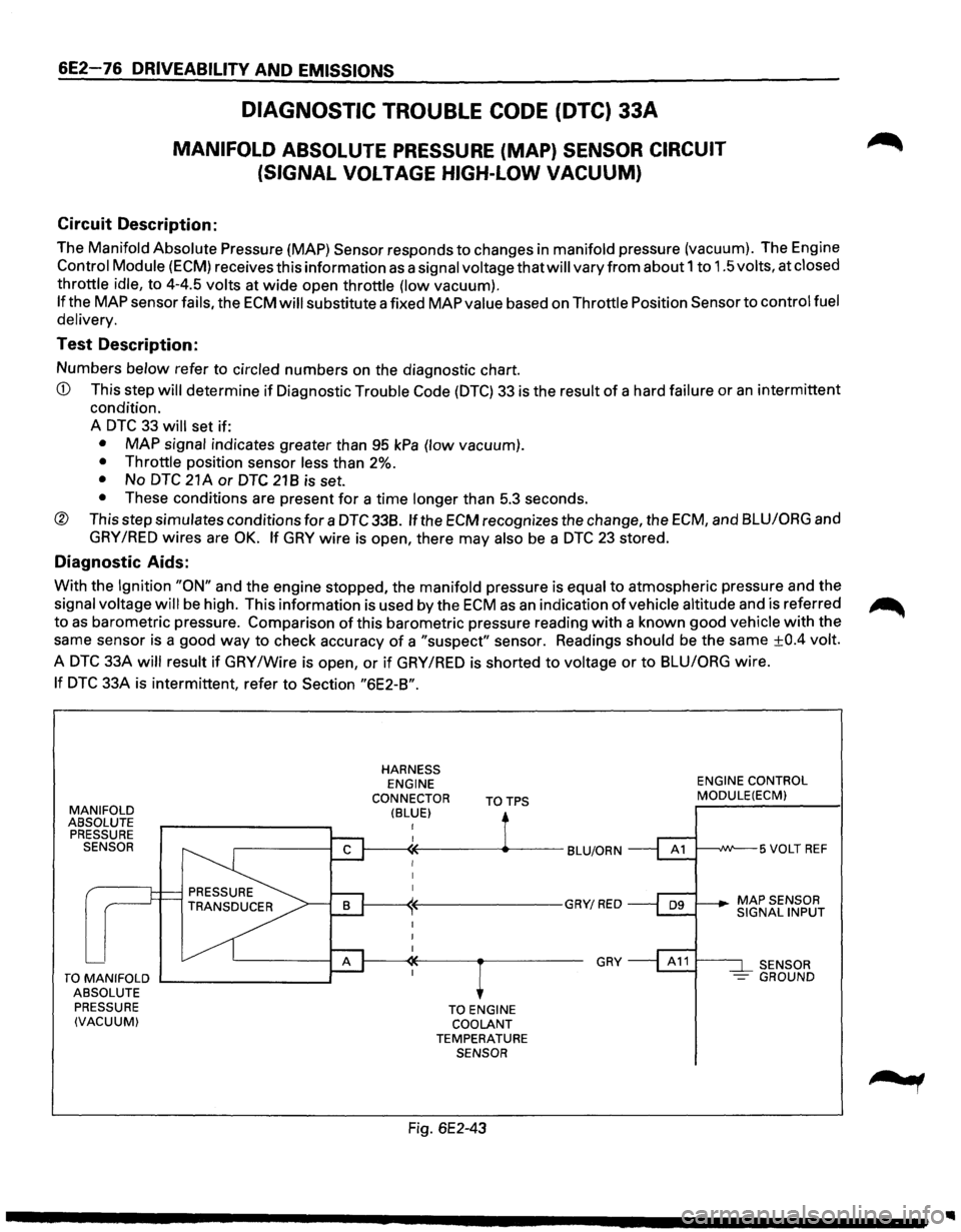
6E2-76 DRIVEABILITY AND EMISSIONS
DIAGNOSTIC TROUBLE CODE (DTC) 33A
MANIFOLD ABSOLUTE PRESSURE (MAP) SENSOR CIRCUIT
(SIGNAL
VOLTAGE HIGH-LOW VACUUM)
Circuit Description:
The Manifold Absolute Pressure {MAP) Sensor responds to changes in manifold pressure (vacuum). The Engine
Control Module (ECM) receives this information as a signal voltage that will vary from about 1 to 1.5 volts, at closed
throttle idle, to 4-4.5 volts at
wide open throttle (low vacuum).
If the MAP sensor fails, the ECM will substitute a fixed MAP value based on Throttle Position Sensor to control fuel
delivery.
Test Description:
Numbers below refer to circled numbers on the diagnostic chart.
CD This step will determine if Diagnostic Trouble Code (DTC) 33 is the result of a hard failure or an intermittent
condition.
A
DTC 33 will set if:
• MAP signal indicates greater than 95 kPa (low vacuum).
• Throttle position sensor less than 2%.
• No DTC 21 A or DTC 21 B is set.
• These conditions are present for a time longer than 5.3 seconds.
® This step simulates conditions for a DTC 338. If the ECM recognizes the change, the ECM, and BLU/ORG and
GRY /RED wires are OK. If GRY wire is open, there may also be a DTC 23 stored.
Diagnostic Aids:
With the Ignition "ON" and the engine stopped, the manifold pressure is equal to atmospheric pressure and the
signal voltage
will be high. This information is used by the ECM as an indication of vehicle altitude and is referred ~
to as barometric pressure. Comparison of this barometric pressure reading with a known good vehicle with the
same sensor is a good
way to check accuracy of a "suspect" sensor. Readings should be the same ±0.4 volt.
A
DTC 33A will result if GRY /Wire is open, or if GRY /RED is shorted to voltage or to BLU/ORG wire.
If DTC 33A is intermittent, refer to Section "6E2-B".
MANIFOLD ABSOLUTE
PRESSURE
SENSOR
TO MANIFOLD ....__ _______ __,
ABSOLUTE
PRESSURE
(VACUUM)
HARNESS ENGINE
CONNECTOR
(BLUE) TOTPS
TO ENGINE
COOLANT
TEMPERATURE SENSOR
Fig. 6E2-43
GRY
ENGINE CONTROL MODULE(ECM)
t---~W--5 VOLT REF
SENSOR
- GROUND
Page 774 of 1928
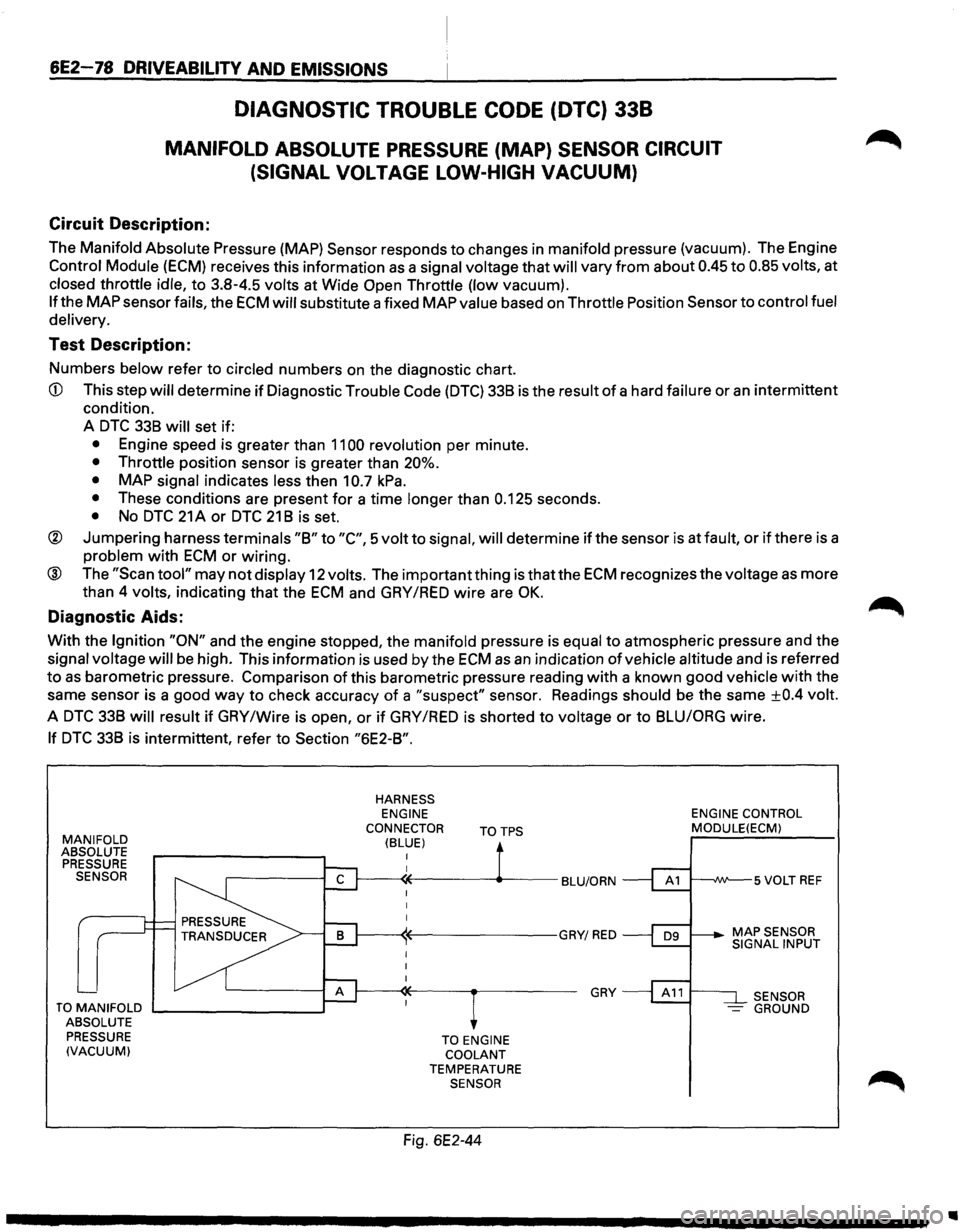
6E2-78 DRIVEABILITV AND EMISSIONS
DIAGNOSTIC TROUBLE CODE (DTC) 338
MANIFOLD ABSOLUTE PRESSURE (MAP) SENSOR CIRCUIT
(SIGNAL
VOLTAGE LOW-HIGH VACUUM)
Circuit Description:
The Manifold Absolute Pressure (MAP) Sensor responds to changes in manifold pressure (vacuum). The Engine
Control Module (ECM) receives this information as a signal voltage that will vary from about 0.45 to 0.85 volts, at
closed throttle idle, to 3.8-4.5 volts at Wide Open Throttle (low vacuum).
If the MAP sensor fails, the ECM will substitute a fixed MAP value based on Throttle Position Sensor to control fuel
delivery.
Test Description:
Numbers below refer to circled numbers on the diagnostic chart.
CD This step will determine if Diagnostic Trouble Code (DTC) 338 is the result of a hard failure or an intermittent
condition.
A
DTC 338 will set if:
• Engine speed is greater than 1100 revolution per minute.
• Throttle position sensor is greater than 20%.
•
MAP signal indicates less then 10.7 kPa.
• These conditions are present for a time longer than 0.125 seconds.
• No DTC 21 A or DTC 21 8 is set.
® Jumpering harness terminals "8" to "C", 5 volt to signal, will determine if the sensor is at fault, or if there is a
problem with ECM or wiring.
® The "Scan tool" may not display 12 volts. The important thing is that the ECM recognizes the voltage as more
than 4
volts, indicating that the ECM and GAY /RED wire are OK.
Diagnostic Aids:
With the Ignition "ON" and the engine stopped, the manifold pressure is equal to atmospheric pressure and the
signal voltage will be high. This information is used by the ECM as an indication of vehicle altitude and is referred
to as barometric pressure. Comparison of this barometric pressure reading with a known good vehicle with the
same sensor is a good
way to check accuracy of a "suspect" sensor. Readings should be the same ±0.4 volt.
A DTC 338 will result if GAY /Wire is open, or if GAY /RED is shorted to voltage or to 8LUIORG wire.
If DTC 338 is intermittent, refer to Section "6E2-8".
MANIFOLD ABSOLUTE
PRESSURE SENSOR
TO MANIFOLD .._ _______ --.~
ABSOLUTE
PRESSURE
(VACUUM)
HARNESS ENGINE
CONNECTOR
(BLUE) TOTPS
TO ENGINE COOLANT TEMPERATURE SENSOR
Fig. 6E2-44
GRY
ENGINE CONTROL MODULE(ECM)
SENSOR -GROUND
..
Page 786 of 1928
6E2-90 DRIVEABILITY AND EMISSIONS
INTERMITTENTS
Definition: Problem may or may not turn "ON" the
"Check Engine" malfunction indicator lamp or store
Diagnostic
Trouble Code (DTC).
DO NOT use the DTC charts in "Engine Components/
Wiring Diagrams/Diagnostic
Charts," Section "6E2-A"
for intermittent problem. The fault must be present to
locate the problem. If a fault is intermittent, use of DTC
charts may result in replacement of good parts.
•
• Most intermittent problems are caused by faulty
electrical
connections or wiring. Perform careful
visual/physical
check as described at start of
"Symptoms," Section "6E2-B." Check for:
Poor mating
of the connector halves. or
terminal not fully seated in the connector body
(backed out).
Improperly formed or damaged terminal. All
connector
terminals in the problem circuit
should be carefully reformed or replaced to
insure proper contact tension.
Poor
terminal to wire connection. This
requires removing the
terminal from the
connector body to check. Refer to
SECTION 8
"Wiring Harness Service,"
If a visual/physical check does not find the cause
of the problem, the car can be driven with a
voltmeter connected to a suspected circuit. A
"Scan tool" can also be used to help detect
intermittent conditions. An abnormal
voltage, or
"Scan" tool reading, when the problem occurs,
indicates the
problem may be in that circuit. If the wiring
and connectors check
OK, and a DTC was
stored
for a circuit having a sensor, except for
DTC(s) 44 and 45, substitute a known good sensor
and recheck.
• Loss of DTC memory. To check, disconnect
throttle position (TP) sensor and idle engine until
"Check
Engine" malfunction indicator lamp comes
"ON". DTC 21 should be stored, and kept in
memory when ignition is turned "OFF". If not, the
Engine
Control Module (ECM) is faulty.
•
An intermittent "Check Engine" malfunction
indicator
lamp with no stored DTC may be caused
by:
Ignition coil shorted to ground and arcing at
spark
plug wires or plugs.
"Check
Engine" malfunction indicator lamp
wire to ECM shorted to ground.
Diagnostic
"test" terminal wire to ECM,
shorted to ground.
ECM grounds, refer to ECM wiring diagrams.
• Check for an electrical system interference caused
by a defective
relay, ECM driven solenoid, or
switch. They can cause a sharp electrical surge.
Normally, the problem will occur when the faulty
component is operated.
• Check for improper installation of electrical
options such as lights, 2 way radios, etc.
• Ignition control wires should be routed away from
spark plug wires, electronic ignition (EI) wires, El
housing, coil and generator. Ground wire from
ECM to El should have a good connection.
• If problem has not been found, refer to "ECM
Connector Symptom" charts at the end of
"Symptoms," Section "6E2-B."
HARD START
Definition: Engine cranks OK, but does not start for a
long time. Does eventually run, or may
start
but immediately dies.
PRELIMINARY CHECKS
• Perform the careful visual/physical checks as
described at start of "Symptoms," Section "6E2-
B".
•
Make sure the driver is using the correct starting
procedure.
SENSORS
• CHECK: Engine coolant temperature sensor using
a
"Scan tool", compare engine coolant
temperature with ambient temperature
on
cold engine. -
If engine coolant temperature
readings
is 5 degrees greater than or less than
ambient air temperature on a
cold
engine, check resistance in engine
coolant temperature sensor circuit
or
sensor itself. Compare engine coolant
temperature sensor resistance value
to the "Diagnostic Aids" chart on
DTC
14 chart.
• CHECK: Manifold absolute pressure sensor.
Check for flooding and/or correct sensor
for vehicle.
• CHECK: TP sensor for binding or a high TP sensor
voltage with the throttle closed (should
read between 0.54 volt and 1.25 volts.)
Page 792 of 1928
6E2-96 DRIVEABILITY AND EMISSIONS
EXCESSIVE EXHAUST EMISSIONS OR ODORS
Definition: Vehicle fails an emission test. Vehicle has
excessive
"rotten egg" smell. Excessive
odors
do not necessarily indicate
excessive emissions.
PRELIMINARY CHECKS
• Perform on-board diagnostic system check.
• IF EMISSION TEST shows excessive CO and
hydrocarbon check items which cause car to run
RICH (Long Term Fuel Trim less than 118), refer to
"Diagnostic Aids" on facing page of diagnostic
trouble code (DTC) 45.
• If EMISSION TEST shows excessive NOx, check
items which cause car
to run lean or too hot.
COOLING SYSTEM
• If the "Scan tool" indicates a very high engine
coolant temperature and the system is running
lean:
CHECK: Engine coolant level
CHECK: Engine thermostat for faulty part
(always open) or for wrong heat range. Refer
to
ENGINE COOLING (SECTION 68).
CHECK: Cooling fan operation.
FUEL SYSTEM
• NOTICE: If the system is running rich (L.T. Fuel
Trim near 118), refer to "Diagnostic Aids"
on facing page
of DTC 45.
-
If the system is running lean (L.T. Fuel
Trim near 142) refer to "Diagnostic
Aids" on facing page of DTC 44.
• CHECK: For properly installed fuel cap.
• CHECK: Fuel pressure. Use CHART A-7.
• CHECK: Canister for fuel loading. Refer to
"Evaporative Emission Control System,"
Section
"6E2-C3."
IGNITION SYSTEM
• CHECK: Ignition timing. Refer to "Vehicle
Emission Control Information" label.
• CHECK: Spark plugs, plug wires, and ignition
components. Refer to
ENGINE
ELECTRICAL (SECTION 6D).
ADDITIONAL CHECKS
• CHECK: For vacuum leaks.
• CHECK: Exhaust gas recirculation valve for not
opening. Use CHART C-7.
• CHECK: For lead contamination of three way
catalytic converter (look for the removal
of fuel filler neck restrictor).
• CHECK: Carbon build-up. Remove carbon with
top engine cleaner. Follow instructions
on can.
• CHECK: PCV valve for being plugged, stuck or
blocked PCV hose or fuel in the
crankcase.
BACKFIRE
Definition: Fuel ignites in intake manifold, or in
exhaust system, making
loud popping
noise.
PRELIMINARY CHECKS
• Perform the careful visual/physical checks as
described at start of "Symptoms," Section "6E2-
B."
IGNITION SYSTEM
• CHECK: Proper ignition coil output voltage with
spark tester J26792 or equivalent (ST-
125).
• CHECK: Spark plugs. Remove spark plugs, check
for
wet plugs, cracks, wear, improper
gap, burned
electrodes, or heavy
deposits. Repair
or replace as necessary.
• CHECK: Spark plug wires for crossfire, also
inspect electronic ignition, spark plug
wires, and proper routing of plug wires.
• CHECK: Ignition timing. Refer to "Vehicle
Emission Control Information" label.
• CHECK: If an intermittent condition exists in the
ignition system, see
"Ignition System/
IGNITION CONTROL," Section "6E2-C4"
or ENGINE ELECTRICAL (SECTION 6D).
ENGINE MECHANICAL
• CHECK: Compression- Look for sticking or leaking
valves.
• CHECK: Valve timing, refer to ENGINE
MECHANICAL DIAGNOSIS (SECTION
6A).
• CHECK: Intake and exhaust manifold passages for
casting
flash.
FUEL SYSTEM
• CHECK: Perform fuel system diagnosis check, see
CHART A-7.
Page 796 of 1928
6E2-100 DRIVEABILITY AND EMISSIONS
SECTION C1
ENGINE CONTROL MODULE (ECM) & SENSORS
CONTENTS
General Description ...................... 6E2-1 00
Engine Control Module (ECM) .............. 6E2-100
Engine Control Module (ECM) Function ....... 6E2-1 00
Information Sensors ..................... 6E2-1 01
Engine Coolant Temperature (ECT) Sensor ... 6E2-101
Intake Air Temperature (IAT) Sensor ........ 6E2-101
Heated Oxygen Sensor (H02S) ........... 6E2-101
Throttle Position
(TP) Sensor ............. 6E2-102
Manifold Absolute Pressure (MAP) Sensor ... 6E2-102
Vehicle Speed Sensor (VSS) ............. 6E2-102
Knock Sensor (KS) (DOHC ONLY) .......... 6E2-102
Air Conditioning (A/C) Request Signal ...... 6E2-1 02
Power Steering Pressure (PSP) Switch ...... 6E2-1 02
Park/Neutral Position (PNP) Switch
(Auto only)
........................ 6E2-1 03 Diagnosis ............................. 6E2-1 03
Engine Control Module (ECM) .............. 6E2-1 03
Electrically Erasable Programmable Read
Only Memory ........................ 6E2-1 03
Engine Control Module (ECM) Inputs ....... 6E2-103
Engine Coolant Temperature (ECT) Sensor ... 6E2-1 04
Intake Air Temperature (IAT) Sensor ........ 6E2-1 04
Heated Oxygen Sensor
(H02S) ........... 6E2-1 04
Throttle Position
(TP) Sensor ............. 6E2-1 04
Manifold Absolute Pressure (MAP) Sensor
... 6E2-1 04
Vehicle Speed Sensor (VSS) ............. 6E2-1 04
Air Conditioning (A/C) Request Signal
Power Steering Pressure
(PSP) Switch ..... .
Crankshaft Position
(CKP) Reference Signal ..
Park/Neutral Position (PNP) Switch ....... .
Knock Sensor
(KS) ................... .
On-Vehicle Service ..................... .
Engine Control Module
(ECM) ............ .
Engine Control Module
(ECM) Replacement ..
Engine Coolant Temperature (ECT) Sensor ... .
Intake Air Temperature (IAT) Sensor ........ .
Heated Oxygen Sensor
(H02S) ............ .
Throttle Position
(TP) Sensor ............. .
Manifold Absolute Pressure (MAP) Sensor
.... .
Vehicle Speed Sensor
(VSS) ............. .
Power Steering Pressure
(PSP) Switch ...... .
Park/Neutral Position
(PNP) Switch ......... .
Chart C-1A Park/Neutral Position
(PNP)
Switch Diagnosis .................... .
Chart
C-1 D Manifold Absolute Pressure (MAP)
Output Check
...................... .
Chart
C-1 E Power Steering Pressure (PSP)
Switch Diagnosis .................... .
Chart
C-1 F Heated Oxygen Sensor (H02S)
Heater Check ....................... .
6E2-104
6E2-104
6E2-104
6E2-104
6E2-104
6E2-104
6E2-104
6E2-105
6E2-105
6E2-106
6E2-106
6E2-107
6E2-107
6E2-107
6E2-107
6E2-107
6E2-108
6E2-110
6E2-112
6E2-114
GENERAL DESCRIPTION
ENGINE CONTROL MODULE (ECM)
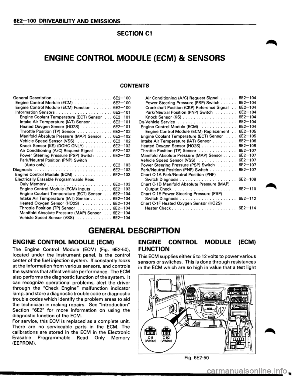
The Engine Control Module (ECM) (Fig. 6E2-50),
located under the instrument panel, is the control
center of the fuel injection system. If constantly looks
at the information from various sensors, and controls
the systems that affect vehicle performance. The ECM
also performs the diagnostic function of the system. It
can recognize operational problems, alert the driver
through the "Check Engine" malfunction indicator
lamp, and store a diagnostic trouble code or diagnostic
trouble codes which identify the problem areas to aid
the technician in making repairs.
See "Introduction"
Section "6E2" for more information on using the
diagnostic function
of the ECM.
For service, this ECM is replaced as a complete unit.
There are no serviceable parts in the
ECM. The
calibrations are stored in the
ECM in the Electronic
Erasable Programmable Read Only Memory
(EEPROM).
ENGINE CONTROL MODULE (ECM)
FUNCTION
This ECM supplies either 5 to 12 volts to power various
sensors
or switches. This is done through resistances
in the
ECM which are so high in value that a test light
Fig. 6E2-50
Page 797 of 1928
will not light when connected to the circuit. In some
cases, even an ordinary shop voltmeter
will not give an
accurate reading because its resistance is
too low.
Therefore, a 10 megohms input impedance digital
voltmeter is required to assure accurate voltage
readings.
The Engine
Control Module (ECM) controls output
circuits such as the fuel injectors, idle air control valve,
air conditioning clutch relay, etc. by controlling the
ground circuit through transistors
or a device called a
"quad-driver".
INFORMATION SENSORS
Engine Coolant Temperature (ECT) Sensor
(Fig. 6E2-51)
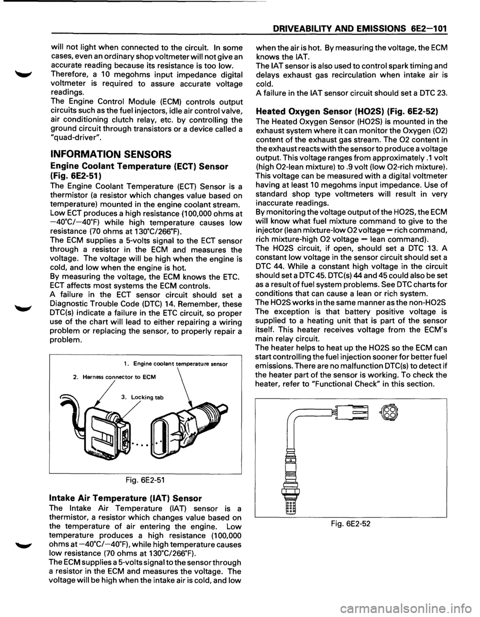
The Engine Coolant Temperature (ECT) Sensor is a
thermistor
(a resistor which changes value based on
temperature) mounted in the engine coolant stream.
Low ECT produces a high resistance (1 00,000 ohms at
-40.C/-40.F) while high temperature causes low
resistance (70 ohms at 130.C/266.F).
The ECM supplies a 5-volts signal to the ECT sensor
through a resistor in the
ECM and measures the
voltage. The voltage
will be high when the engine is
cold, and low when the engine is hot.
By measuring the voltage, the
ECM knows the ETC.
ECT affects most systems the ECM controls.
A failure in the
ECT sensor circuit should set a
Diagnostic Trouble Code
(DTC) 14. Remember, these
DTC(s) indicate a failure in the
ETC circuit, so proper
use
of the chart will lead to either repairing a wiring
problem or replacing the sensor, to properly repair a
problem.
1. Engine coolant temperature sensor
2. Harness connector to ECM
3. Locking tab
Fig. 6E2-51
Intake Air Temperature (IAT) Sensor
The Intake Air Temperature (IAT) sensor is a
thermistor, a resistor which changes
value based on
the temperature
of air entering the engine. Low
temperature produces a high resistance
(1 00,000
ohms at -4o·c/-40.F), while high temperature causes
low resistance (70 ohms at 130.C/266.F).
The ECM supplies a 5-volts signal to the sensor through
a resistor in the
ECM and measures the voltage. The
voltage
will be high when the intake air is cold, and low
DRIVEABILITV AND EMISSIONS 6E2-1 01
when the air is hot. By measuring the voltage, the ECM
knows the lAT.
The IAT sensor is also used to control spark timing and
delays exhaust gas recirculation when intake air is
cold.
A failure in the IAT sensor circuit should set a DTC 23.
Heated Oxygen Sensor (H02S) (Fig. 6E2-52)
The Heated Oxygen Sensor (H02S) is mounted in the
exhaust system where
it can monitor the Oxygen (02)
content of the exhaust gas stream. The 02 content in
the exhaust reacts
with the sensor to produce a voltage
output. This voltage ranges
from approximately .1 volt
(high 02-lean mixture) to .9 volt (low 02-rich mixture).
This voltage can
be measured with a digital voltmeter
having at
least 10 megohms input impedance. Use of
standard shop type voltmeters will result in very
inaccurate readings.
By monitoring the voltage
output ofthe H02S, the ECM
will know what fuel mixture command to give to the
injector
(lean mixture-low 02 voltage= rich command,
rich mixture-high
02 voltage= lean command).
The
H02S circuit, if open, should set a DTC 13. A
constant
low voltage in the sensor circuit should set a
DTC 44. While a constant high voltage in the circuit
should set a DTC 45. DTC(s) 44 and 45 could also be set
as a result of fuel system problems. See DTC charts for
conditions that can cause a lean or rich system.
The
H02S works in the same manner as the non-H02S
The exception is that battery positive voltage is
supplied to a heating unit that is part of the sensor
itself. This heater receives voltage
from the ECM's
main
relay circuit.
The heater
helps to heat up the H02S so the ECM can
start
controlling the fuel injection sooner for better fuel
emissions. There are no malfunction DTC(s) to detect if
the heater part of the sensor is working. To check the
heater, refer to "Functional
Check" in this section.
Fig. 6E2-52
~
\W