warning light ISUZU TROOPER 1995 Manual PDF
[x] Cancel search | Manufacturer: ISUZU, Model Year: 1995, Model line: TROOPER, Model: ISUZU TROOPER 1995Pages: 1928
Page 1506 of 1928
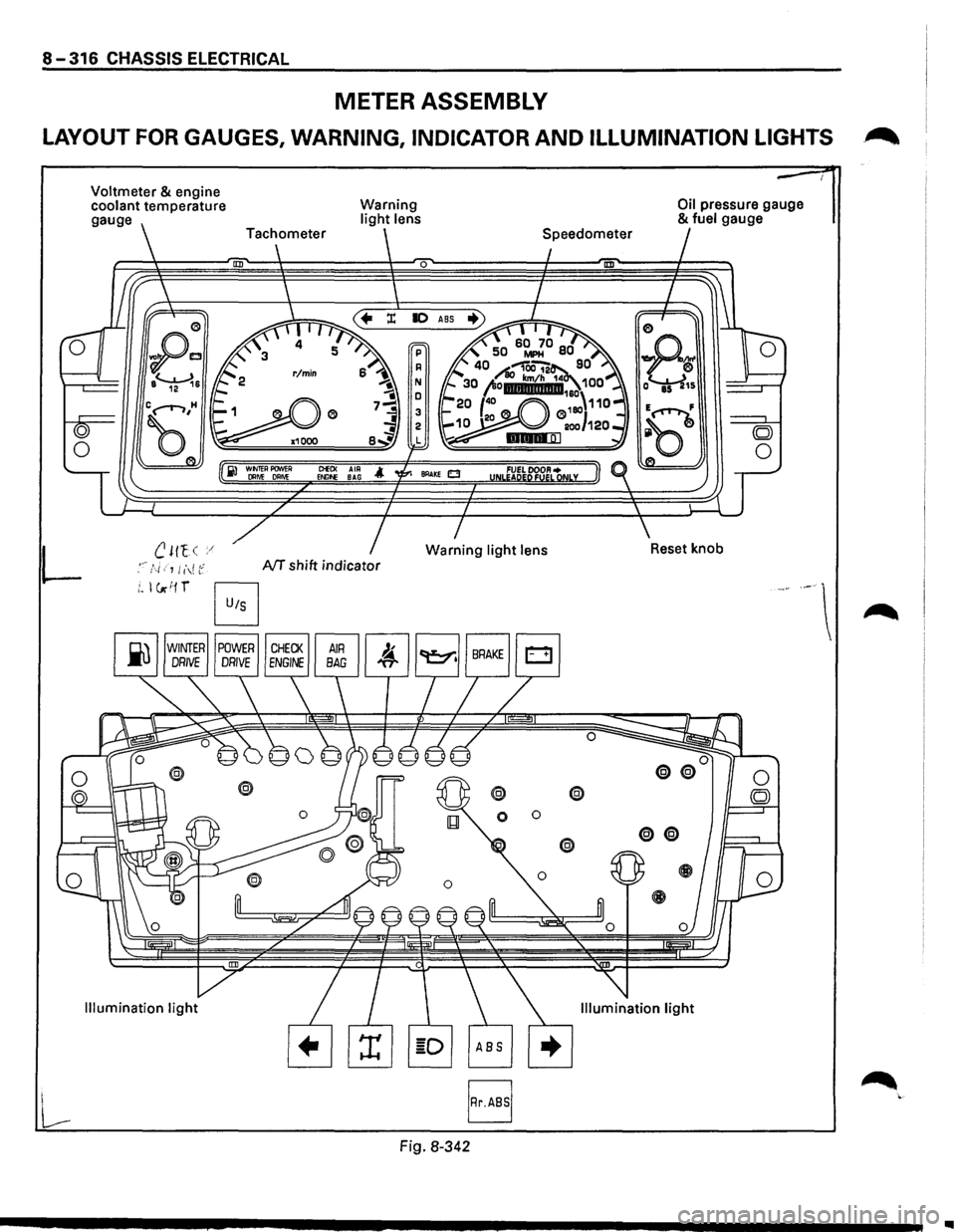
8-316 CHASSIS ELECTRICAL
METER ASSEMBLY
LAYOUT FOR GAUGES, WARNING, INDICATOR AND ILLUMINATION LIGHTS .~
L
Voltmeter & engine
coolant temperature
gauge
B
Warning light lens
0
ClEO< AIR Et.llf>E BAG
NT shift indicator
Fig. 8-342
@ @
0 0
Oil pressure gauge & fuel gauge
..
Page 1507 of 1928
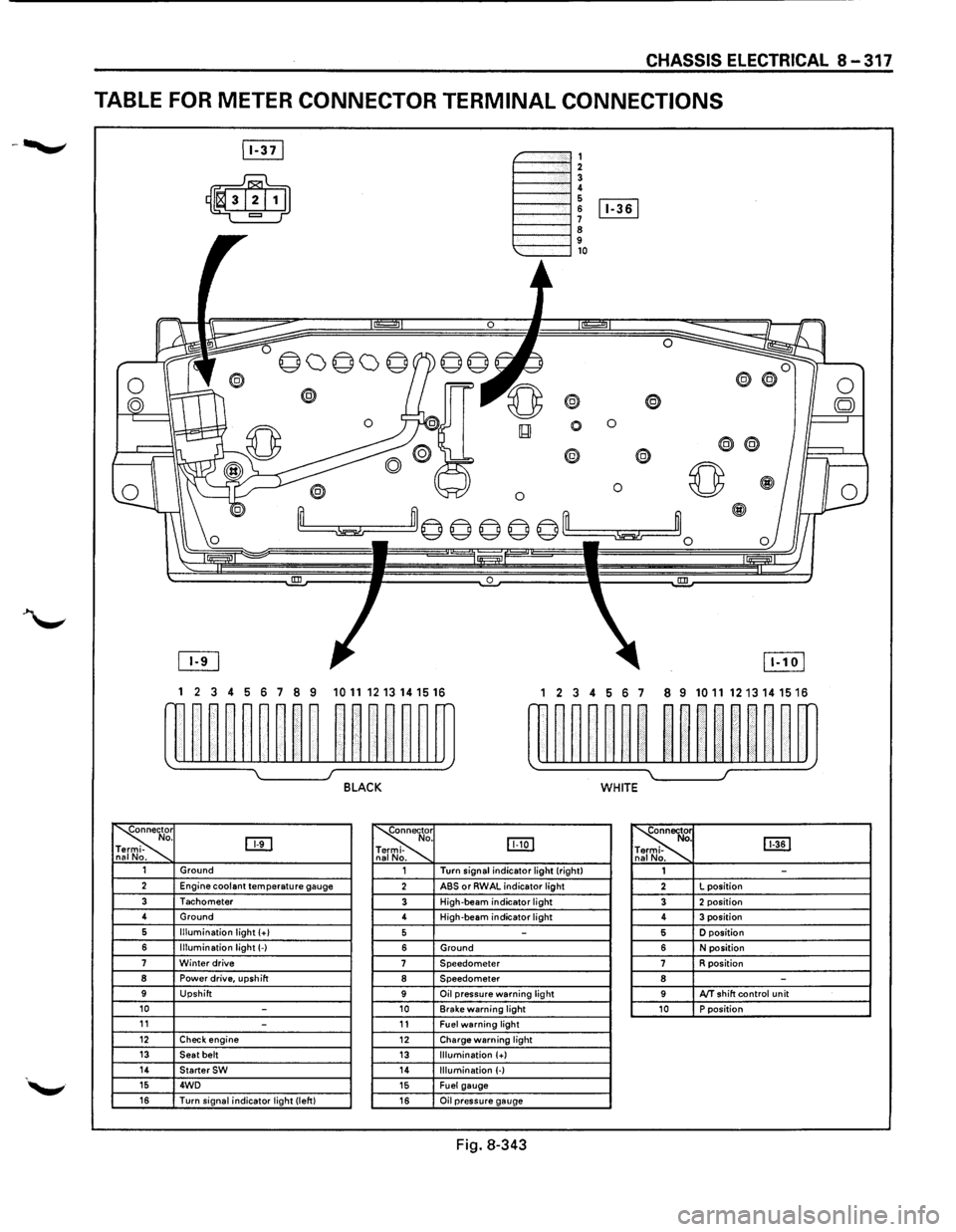
CHASSIS ELECTRICAL 8-317
TABLE FOR METER CONNECTOR TERMINAL CONNECTIONS
~-""""""', 1----""'12 1----""'1! 6 1----l 6 [Iill
1----""'1 ~ 9 1---""'l,o
®
0 0
0
® @
0 0 ~
~m© © © © ©'--m ~~0
0 !III
1 2 3 4 5 6 7 8 9 1011 1213141516 1 2 3 4 56 7 8 9 10111213141516
w~~~~~~~~ ~~~~~~m rn~~~~~~ ~~nn~~m
~ I J BLACK WHITE
~r o. DTI -na No. ~
. IJJ:Q] -
. ~ [ill] . -. 1 Ground 1 Turn
signal indicator light (right)
1 -2 Engine coolant temperature gauge 2 ABS or RWAL indicator light 2 L
position
3 Tachometer 3 High-beam indicator light 3 2 position 4
Ground
4 High-beam
indicator light 4 3 position 6 Illumination light (+I 5 -5 D position
6 Illumination light(-) 6 Ground 6 N position 7 Winter drive 7 Speedometer 7 R position 8 Power drive, upshift 8 Speedometer 8 -9 Upshift 9 Oil pressure warning light 9 AfT shift control unit 10 -10 Brake warning light 10 P position 11 -11 Fuel warning light 12 Check engine 12 Charge warning light 13 Seat belt 13 Illumination (+) 14 StarterSW 14 Illumination (-) 15 4WD 15 Fuel gauge 16 Turn signal indicator light (left) 16 Oil pressure gauge
Fig. 8-343
Page 1517 of 1928
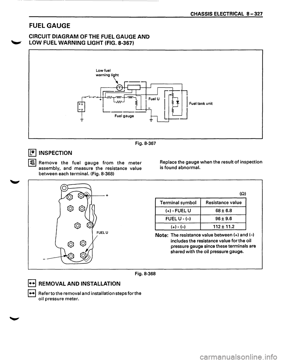
CHASSIS ELECTRICAL 8 -327
FUEL GAUGE
CIRCUIT DIAGRAM OF THE FUEL GAUGE AND
'--"' LOW FUEL WARNING LIGHT (FIG. 8-367)
Low fuel
Fuel gauge
Fig. 8-367
~ INSPECTION
lt!tl Remove the fuel gauge from the meter
assembly, and measure the resistance value
between each terminal. (Fig. 8-368) Replace
the gauge when the result
of inspection
is found abnormal.
(Q)
Terminal symbol Resistance
value
(+)-FUEL U
68± 6.8
FUEL U-(-) 96± 9.6
(+)- (-)
112 ± 11.2
Note: The resistance value between(+) and H
includes the resistance value
for the oil
pressure gauge since these terminals are
shared with the
oil pressure gauge.
Fig. 8-368
B REMOVAL AND INSTALLATION
1•,.1 Refer to the removal and installation steps for the
oil pressure meter.
Page 1518 of 1928
8-328 CHASSIS ELECTRICAL
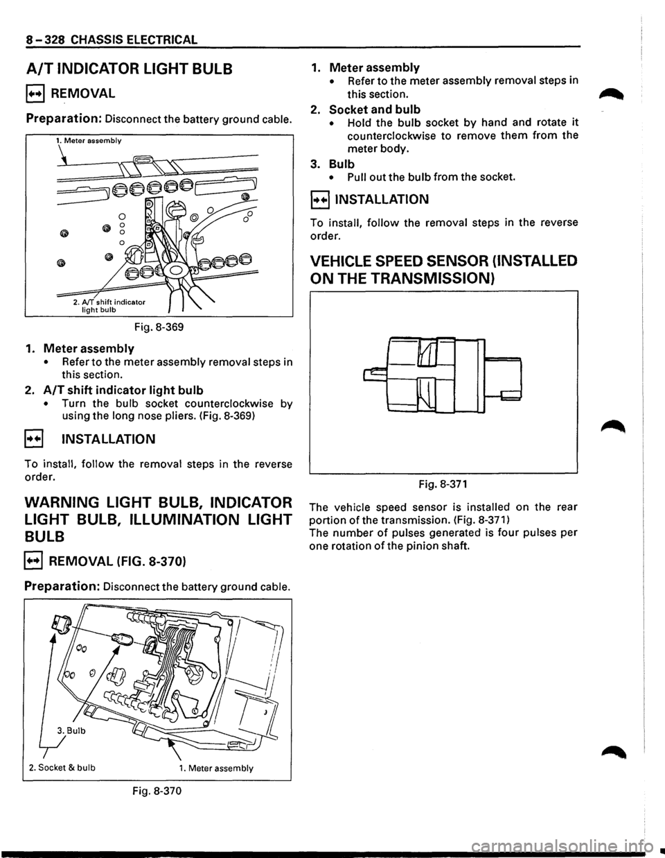
A/T INDICATOR LIGHT BULB
B REMOVAL
Preparation: Disconnect the battery ground cable.
Fig.
8-369
1. Meter assembly
• Refer to the meter assembly removal steps in
this section.
2.
A/T shift indicator light bulb
• Turn the bulb socket counterclockwise by
using the
long nose pliers. (Fig. 8-369)
B INSTALLATION
To install, follow the removal steps in the reverse
order.
WARNING LIGHT BULB, INDICATOR
LIGHT
BULB, ILLUMINATION LIGHT
BULB
B REMOVAL (FIG. 8-370)
Preparation: Disconnect the battery ground cable.
2. Socket & bulb 1. Meter assembly
Fig. 8-370
1. Meter assembly
• Refer to the meter assembly removal steps in
this section.
2.
Socket and bulb
• Hold the bulb socket by hand and rotate it
counterclockwise to remove them from the
meter body.
3.
Bulb
• Pull out the bulb from the socket.
B INSTALLATION
To install, follow the removal steps in the reverse
order.
VEHICLE SPEED SENSOR (INSTALLED
ON
THE TRANSMISSION)
Fig. 8-371
The vehicle speed sensor is installed on the rear
portion of the transmission. (Fig. 8-371)
The number of pulses generated is four pulses per
one rotation
of the pinion shaft.
..
Page 1521 of 1928
![ISUZU TROOPER 1995 Manual PDF OIL PRESSURE UNIT
(1!] INSPECTION
Measure the resistance value ofthe oil pressure unit
with the circuit tester. (Fig. 8-377)
Replace the
unit when the result of inspection is found
abnorm](/img/61/57183/w960_57183-1520.png "ISUZU TROOPER 1995 Manual PDF OIL PRESSURE UNIT
(1!] INSPECTION
Measure the resistance value ofthe oil pressure unit
with the circuit tester. (Fig. 8-377)
Replace the
unit when the result of inspection is found
abnorm")
OIL PRESSURE UNIT
(1!] INSPECTION
Measure the resistance value ofthe oil pressure unit
with the circuit tester. (Fig. 8-377)
Replace the
unit when the result of inspection is found
abnormal.
Pressure
(kPa)
Resistance value (Q)
Fig. 8-377
OIL PRESSURE SWITCH
(1!] INSPECTION
98 981
81 30
I~~ Check the continuity between the switch termi
nal and the body ground with the engine at idle.
(Fig. 8-378)
Replace the switch when the result
of inspection
is
found abnormal.
Fig. 8-378
CHASSIS ELECTRICAL 8-331
(1!] CIRCUIT INSPECTION (FIG. 8-379)
Fig. 8-379
1. Start the engine.
2. When disconnecting the oil pressure switch con
nector then connecting the harness side connec
tor to the ground, check to see if the oil pressure
warning light lights up.
When the
light will not light up, check the circuit
between the meter and the oil pressure switch,
and repair
an open circuit if necessary.
FUEL TANK UNIT
The tank unit varies the internal resistance according
to the float position (fluid level) to operate the fuel
meter needle.
It is also designed
to warn the driver of low fuel level
by illuminating the fuel warning light. (Fig. 8-380)
Fig. 8-380
Page 1522 of 1928
![ISUZU TROOPER 1995 Manual PDF 8-332 CHASSIS ELECTRICAL
i1!]1NSPECTION
~1.
£ ·= 01 ~ N ~ !:!i E
E
E E
0 M (I) ..., ... ...
Check the resistance between the connector
terminals 1 [E[I and 2 [E[J while shifting
the fl](/img/61/57183/w960_57183-1521.png "ISUZU TROOPER 1995 Manual PDF 8-332 CHASSIS ELECTRICAL
i1!]1NSPECTION
~1.
£ ·= 01 ~ N ~ !:!i E
E
E E
0 M (I) ..., ... ...
Check the resistance between the connector
terminals 1 [E[I and 2 [E[J while shifting
the fl")
8-332 CHASSIS ELECTRICAL
i1!]1NSPECTION
~1.
£ ·= 0'1 ~ N ~ !:!i E
E
E E
0 M (I) ..., ... ...
Check the resistance between the connector
terminals 1 [E[I and 2 [E[J while shifting
the float from "E" to "F" point.
When
the resistance shows no change, or
deflects largely from the specified value, re
place the fuel tank unit. (Fig. 8-381)
F
E .:: E~ ...... ...,::;
X
E
NOTE:
When the resistance value at E point is checked,
connect
the terminal 2 ~ to the battery (+) ter
minal and 1 [E[] to the battery (-) terminal under
the condition that ambient temperature is between
20°C and 30°C (68°F and 86°F).
.. ,
I I I
·-·
Float position Resistance value (Q)
F point 17 ± 0.8
1/2 point 45± 1.5
E
point 120±5
Fig. 8-381
2. Check the resistance value between the fuel tank 1++1 REMOVAL (FIG. 8-383) unit connector terminals 1 ~and 4 [£:[].
(Fig. 8-382) Preparation: Disconnect the battery ground cable.
Replace the fuel tank unit when the result of
inspection is found abnormal.
Float
position Terminal No. Resistance
value (Q)
X point Undercover (Light up point 1-4 35.9-18 of low fuel Fig.
8-383 warning light)
Fig. 8-382
Ill
Page 1523 of 1928
1. Fuel tank
• Refer to fuel tank removal steps in Section 6C
"ENGINE FUEL."
2. Fuel tank unit
• Disconnect the connectors.
• Remove the five screws.
B INSTALLATION
To install, follow the removal steps in the reverse
order.
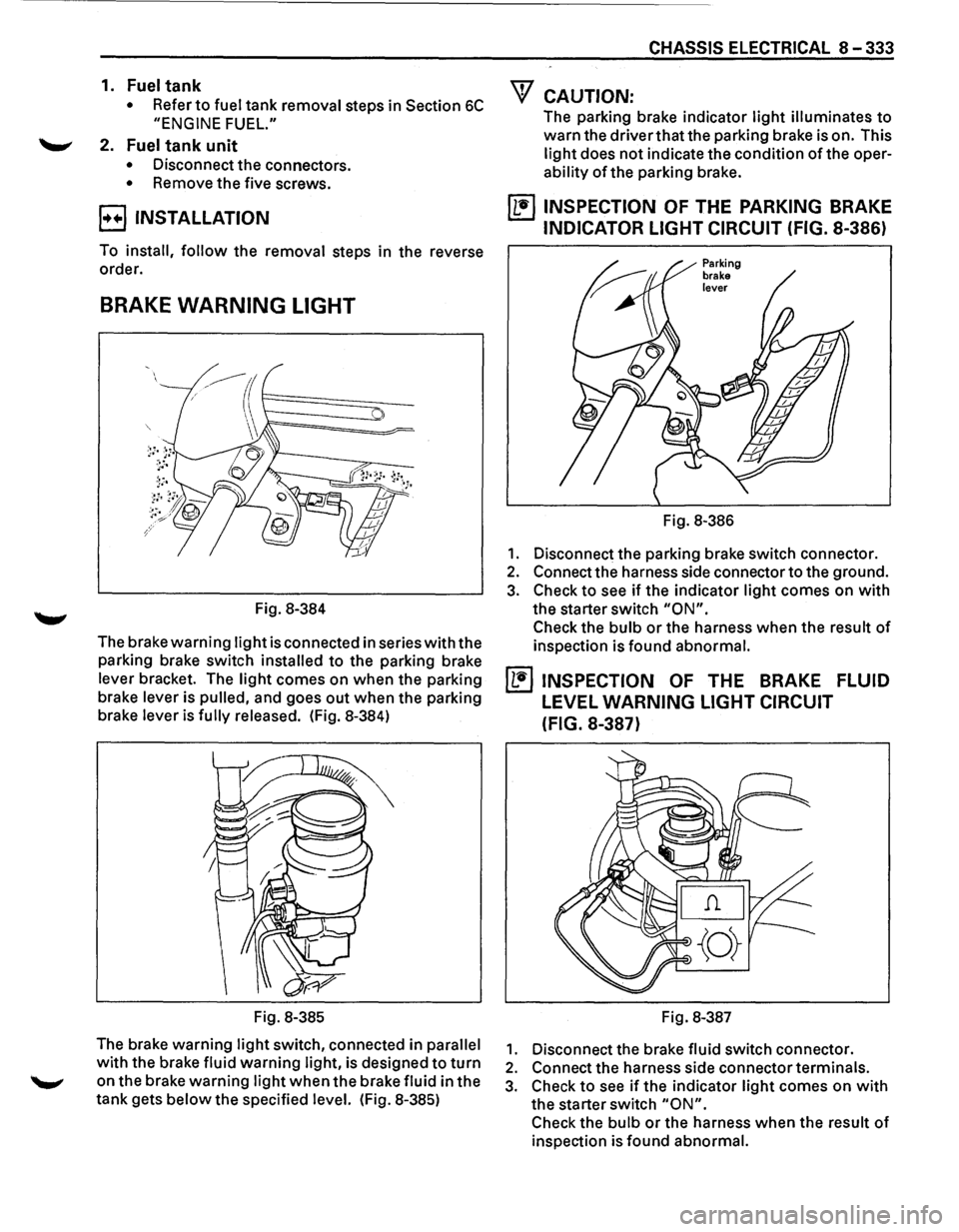
BRAKE WARNING LIGHT
Fig. 8-384
The brake
warning light is connected in series with the
parking brake switch
installed to the parking brake
lever bracket. The
light comes on when the parking
brake lever is
pulled, and goes out when the parking
brake lever is
fully released. (Fig. 8-384)
Fig. 8-385
The brake warning
light switch, connected in parallel
with the brake fluid warning light, is designed to turn
on the brake warning light when the brake fluid in the
tank gets
below the specified level. (Fig. 8-385)
CHASSIS ELECTRICAL 8-333
"f CAUTION:
The parking brake indicator light illuminates to
warn the driver that the parking brake is on. This
light does not indicate the condition of the oper
ability of the parking brake.
~ INSPECTION OF THE PARKING BRAKE
INDICATOR LIGHT CIRCUIT (FIG. 8-386)
Fig. 8-386
1. Disconnect the parking brake switch connector.
2. Connect the harness side connector to the ground.
3. Check to see if the indicator light comes on with
the starter switch "ON".
Check the bulb or the harness when the result of
inspection is found abnormal.
~ INSPECTION OF THE BRAKE FLUID
LEVEL WARNING LIGHT CIRCUIT
(FIG.
8-387)
Fig. 8-387
1. Disconnect the brake fluid switch connector.
2. Connect the harness side connector terminals.
3. Check to see if the indicator light comes on with
the starter switch "ON".
Check the bulb or the harness when the result of
inspection is found abnormal.
Page 1572 of 1928
8-382 CHASSIS ELECTRICAL
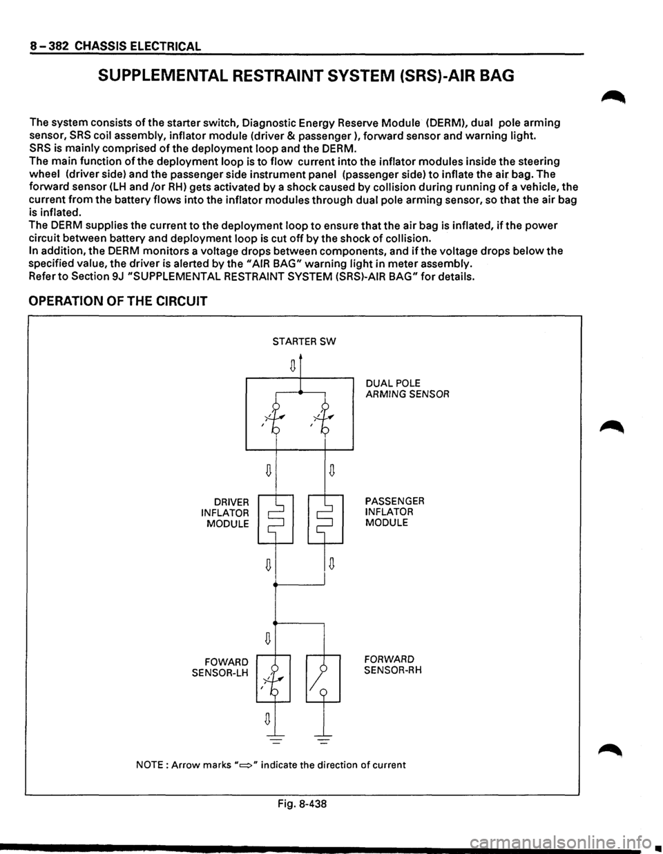
SUPPLEMENTAL RESTRAINT SYSTEM (SRS)-AIR BAG
The system consists of the starter switch, Diagnostic Energy Reserve Module (OERM), dual pole arming
sensor,
SRS coil assembly, inflator module (driver & passenger), forward sensor and warning light.
SRS is mainly comprised of the deployment loop and the DERM.
The main function of the deployment loop is to flow current into the inflator modules inside the steering
wheel (driver side) and the passenger side instrument panel (passenger side) to inflate the air bag. The
forward sensor
(LH and /or RH) gets activated by a shock caused by collision during running of a vehicle, the
current
from the battery flows into the inflator modules through dual pole arming sensor, so that the air bag
is
inflated.
The DERM supplies the current to the deployment loop to ensure that the air bag is inflated, if the power
circuit between battery and deployment loop is cut off by the shock of collision.
In
addition, the DERM monitors a voltage drops between components, and if the voltage drops below the
specified
value, the driver is alerted by the "AIR BAG" warning light in meter assembly.
Refer to Section 9J "SUPPLEMENTAL RESTRAINT SYSTEM (SRS)-AIR BAG" for details.
OPERATION OF THE CIRCUIT
DRIVER
INFLATOR MODULE
FOWARD
SENSOR-LH
D
D
STARTER SW
D
1
DUAL POLE ARMING SENSOR
PASSENGER
INFLATOR
MODULE
FORWARD
SENSOR-RH
NOTE: Arrow marks "c::::>" indicate the direction of current
Fig. 8-438
•
Page 1620 of 1928
9B-36 CRUISE CONTROL
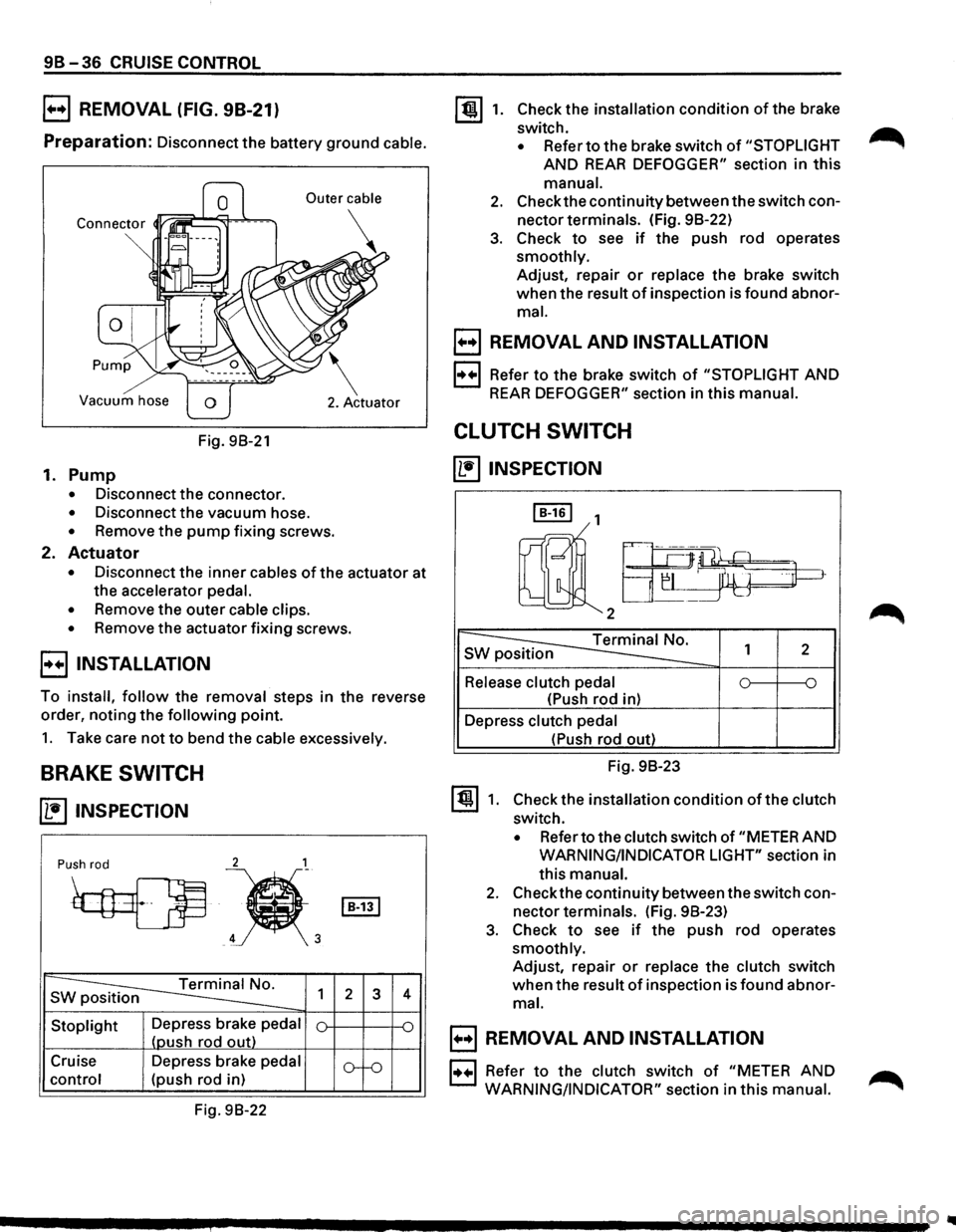
B REMOVAL (FIG. 98-21)
Preparation: Disconnect the battery ground cable.
Vacuum hose
Fig. 98-21
1. Pump
• Disconnect the connector.
• Disconnect the vacuum hose.
• Remove the pump fixing screws.
2. Actuator
• Disconnect the inner cables of the actuator at
the accelerator
pedal.
•
Remove the outer cable clips.
• Remove the actuator fixing screws.
E) INSTALLATION
To install, follow the removal steps in the reverse
order, noting
the following point.
1. Take care not to bend the cable excessively.
BRAKE SWITCH
~ INSPECTION
2 1
Push rod
~
~'
s ~ 1
Stoplight Depress brake pedal
(oush rod out)
Cruise Depress brake
pedal
control (push rod in)
Fig. 98-22
I B-131
2 3
o--o
4
~1. Check the installation condition of the brake
switch.
• Refer to the brake switch of "STOPLIGHT
AND REAR DEFOGGER" section in this
manual.
2. Check the continuity between the switch con
nector terminals. (Fig. 98-22)
3. Check to see if the push rod operates
smoothly. Adjust, repair
or replace the brake switch
when the result
of inspection is found abnor
mal.
B REMOVAL AND INSTALLATION
1·++·1 Refer to the brake switch of "STOPLIGHT AND
REAR DEFOGGER" section in this manual.
CLUTCH SWITCH
~INSPECTION
I B-161 1
rnll2a-~~
~ s 1 2
Release clutch pedal 0 ~ ~
(Push rod in)
Depress
clutch pedal
~1.
(Push rod out)
Fig. 98-23
Check the installation
condition of the clutch
switch.
• Refer to the clutch switch of "METER AND
WARNING/INDICATOR LIGHT" section in
this
manual.
2. Check the continuity between the switch con
nector terminals. (Fig. 98-23)
3. Check to see if the push rod operates
smoothly. Adjust, repair
or replace the clutch switch
when the result of inspection is found abnor
mal.
B REMOVAL AND INSTALLATION
1••1 Refer to the clutch switch of "METER AND ...-...
WARNING/INDICATOR"
section in this manual. ,...........
Page 1622 of 1928
![ISUZU TROOPER 1995 Manual PDF 98-38 CRUISE CONTROL
VEHICLE SPEED SENSOR (INCORPO
RATED IN SPEEDOMETER)
(1!] INSPECTION
GND GND
SEN 4P
~
I Red(+) Black(-) Black(-) Red(+)
a
I
4P GND 4P GND
4P-GND
13.5K-16.5K 00
Note:](/img/61/57183/w960_57183-1621.png "ISUZU TROOPER 1995 Manual PDF 98-38 CRUISE CONTROL
VEHICLE SPEED SENSOR (INCORPO
RATED IN SPEEDOMETER)
(1!] INSPECTION
GND GND
SEN 4P
~
I Red(+) Black(-) Black(-) Red(+)
a
I
4P GND 4P GND
4P-GND
13.5K-16.5K 00
Note:")
98-38 CRUISE CONTROL
VEHICLE SPEED SENSOR (INCORPO
RATED IN SPEEDOMETER)
(1!] INSPECTION
GND GND
SEN 4P
~
I Red(+) Black(-) Black(-) Red(+)
a
I
4P GND 4P GND
4P-GND
13.5K-16.5K 00
Note: Use an analog type circuit tester.
Fig. 98-25
~~~ Removethespeedometerfromthemeterassem-DIODE
bly, and measure the resistance value between
the
terminals. (Fig. 98-26) IL•IINSPECTION
Replace the speedometer assembly when the
result of inspection is found abnormal.
B REMOVAL AND INSTALLATION
1•+1 Refer to Section 8 "METER AND WARNING/
INDICATOR LIGHT"
for vehicle speed sensor
removal and installation steps.
I B-451
~
Terminal No. 1 2
Connection A
G 0
pattern
0 G 8
Fig.
98-26
I~~ There should be continuity in either A or 8 when
a circuit tester is connected
with diode terminal.
(Fig. 98-26)
Replace the diode when the result of inspection
is
found abnormal.
..