ISUZU TROOPER 1995 Workshop Manual
Manufacturer: ISUZU, Model Year: 1995, Model line: TROOPER, Model: ISUZU TROOPER 1995Pages: 1928
Page 851 of 1928
DRIVEABILITY AND EMISSIONS 6E2-155
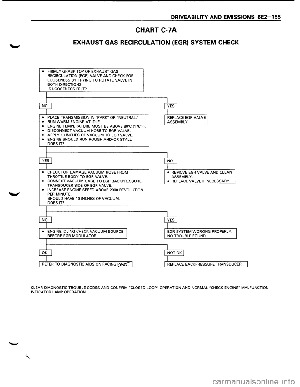
CHART C-7A
EXHAUST GAS RECIRCULATION (EGR) SYSTEM CHECK
• FIRMLY GRASP TOP OF EXHAUST GAS
RECIRCULATION (EGR} VALVE AND CHECK FOR LOOSENESS BY TRYING TO ROTATE VALVE IN BOTH DIRECTIONS. IS LOOSENESS FELT?
• PLACE TRANSMISSION IN "PARK" OR "NEUTRAL."
• RUN WARM ENGINE AT IDLE. • ENGINE TEMPERATURE MUST BE ABOVE so·c (176.F}. • DISCONNECT VACUUM HOSE TO EGR VALVE. • APPLY 10 INCHES OF VACUUM TO EGR VALVE. • ENGINE SHOULD RUN ROUGH AND/OR STALL.
DOES IT?
• CHECK FOR DAMAGE VACUUM HOSE FROM THROTILE BODY TO EGR VALVE. • CONNECT VACUUM GAGE TO EGR BACKPRESSURE
TRANSDUCER SIDE OF EGR VALVE. • INCREASE ENGINE SPEED ABOVE 2000 REVOLUTION PER MINUTE. SHOULD HAVE 10 INCHES OF VACUUM. DOES IT?
• ENGINE IDLING CHECK VACUUM SOURCE BEFORE EGR MODULATOR.
• REMOVE EGR VALVE AND CLEAN
ASSEMBLY.
•
REPLACE VALVE IF NECESSARY.
EGR SYSTEM WORKING PROPERLY. NO TROUBLE FOUND.
REPLACE
BACKPRESSURE TRANSDUCER.
CLEAR DIAGNOSTIC
TROUBLE CODES AND CONFIRM "CLOSED LOOP" OPERATION AND NORMAL "CHECK ENGINE" MALFUNCTION
INDICATOR LAMP OPERATION.
Page 852 of 1928
6E2-156 DRIVEABILITY AND EMISSIONS
MEMO
Page 853 of 1928
DRIVEABILITY AND EMISSIONS 6E2-157
SECTION C-8
SHIFT INDICATOR LIGHT (MIT ONLY)
CONTENTS
General Description . . . . . . . . . . . . . . . . . . . . . 6E2-157 Diagnosis ............................. 6E2-157
Purpose ............................ 6E2-157 Transmission Switch Functional Check ..... 6E2-157
Operation . . . . . . . . . . . . . . . . . . . . . . . . . . . 6E2-157 Clutch Switch Functional Check ........... 6E2-157
Chart C-8 Manual Transmission (M/T)
Shift Light ........................... 6E2-158
GENERAL DESCRIPTION
PURPOSE
The shift indicator light is a device which is installed in
the instrument
panel to urge the driver to up shiftatthe
proper moment. This insures operations for best fuel
economy.
OPERATION
It turns on as soon as vehicle conditions become
suitable for operation in the next higher gear, and turns
off as the clutch is released for up shift.
The engine parameters used
to activate the shift
indicator
light are engine speed, engine load and
engine
coolant temperature. The engine load is sensed
as a function of Throttle Body (TB) position by a sensor
built into the TB. The
shift indicator
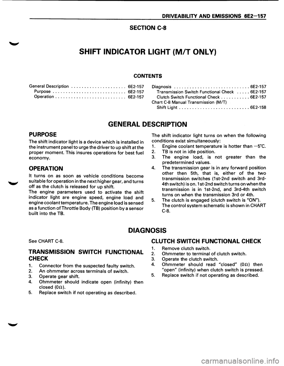
light turns on when the following
conditions exist simultaneously:
1. Engine coolant temperature is hotter than -s·c.
2. TB is not in idle position.
3. The engine load, is not greater than the
predetermined
values.
4. The transmission gear is in any forward position
other then 5th, that is, either
of the two
transmission switches (1st-2nd switch and 3rd-
4th switch) is on. 1st-2nd switch turns on
when the
transmission is in 1st-2nd, and 3rd-4th switch
turns on when the transmission 3rd
or 4th.
5. The clutch is engaged (clutch switch is "ON").
The control system schematic is shown in CHART
C-8.
DIAGNOSIS
See CHART C-8.
TRANSMISSION SWITCH FUNCTIONAL
CHECK
1. Connector from the suspected faulty switch.
2. An ohmmeter across terminals of switch.
3. Operate gear shift.
4. Ohmmeter should indicate open (infinity) then
closed (00).
5. Replace switch if not operating as described.
CLUTCH SWITCH FUNCTIONAL CHECK
1. Remove clutch switch.
2. Ohmmeter to terminal of clutch switch.
3. Operate the clutch switch.
4. Ohmmeter should read "closed" (00) then
"open" (infinity) when clutch switch is pressed.
5. Replace switch if not operating as described.
Page 854 of 1928
6E2-158 DRIVEABILITV AND EMISSIONS
CHART C-8
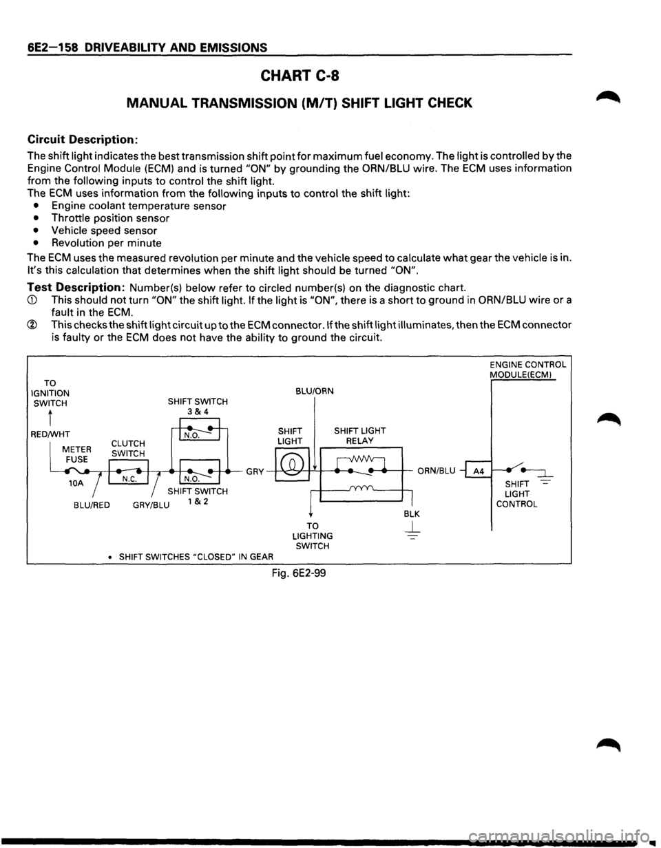
MANUAL TRANSMISSION (M/T) SHIFT LIGHT CHECK
Circuit Description:
The shift light indicates the best transmission shift point for maximum fuel economy. The light is controlled by the
Engine Control Module
(ECM) and is turned "ON" by grounding the ORN/BLU wire. The ECM uses information
from the following inputs to control the shift light.
The
ECM uses information from the following inputs to control the shift light:
• Engine coolant temperature sensor
• Throttle position sensor
• Vehicle speed sensor
• Revolution per minute
The
ECM uses the measured revolution per minute and the vehicle speed to calculate what gear the vehicle is in.
It's this calculation that determines when the shift light should be turned "ON".
Test Description: Number(s) below refer to circled number(s) on the diagnostic chart.
ECM.
® This checks the shift light circuit up to the ECM connector .If the shift light illuminates, then the ECM connector
is faulty
or the ECM does not have the ability to ground the circuit.
TO
IGNITION SWITCH
t
BLU/RED GRY/BLU
•
SHIFT SWITCHES #CLOSED" IN GEAR
BLU/ORN
SHIFT SHIFT LIGHT
LIGHT
RELAY
TO
LIGHTING SWITCH
Fig. 6E2-99
ENGINE CONTROL
MODULE(ECMl
SHIFT
LIGHT
CONTROL
Page 855 of 1928
DRIVEABILITY AND EMISSIONS 6E2-159
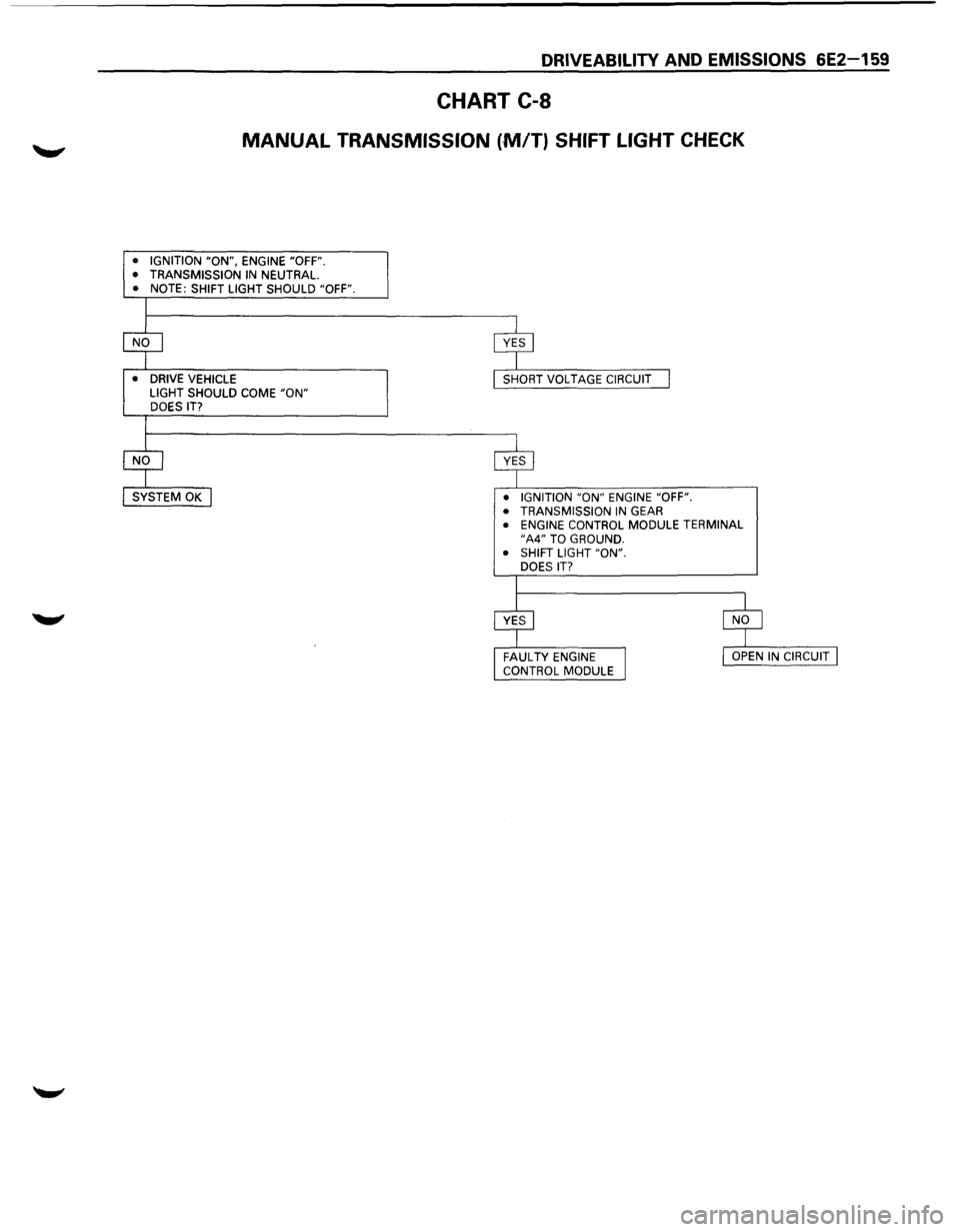
CHART C-8
MANUAL TRANSMISSION (,MfT) SHIFT LIGHT CHECK
• IGNITION "ON", ENGINE "OFF".
• TRANSMISSION IN NEUTRAL. • NOTE: SHIFT LIGHT SHOULD "OFF".
•
DRIVE VEHICLE
LIGHT SHOULD COME "ON" DOES IT?
• IGNITION
"ON" ENGINE "OFF".
• TRANSMISSION IN GEAR • ENGINE CONTROL MODULE TERMINAL "A4" TO GROUND.
• SHIFT LIGHT "ON".
DOES
IT?
Page 856 of 1928
6E2-160 DRIVEABILITY AND EMISSIONS
MEMO
Page 857 of 1928
DRIVEABILITV AND EMISSIONS 6E2-161
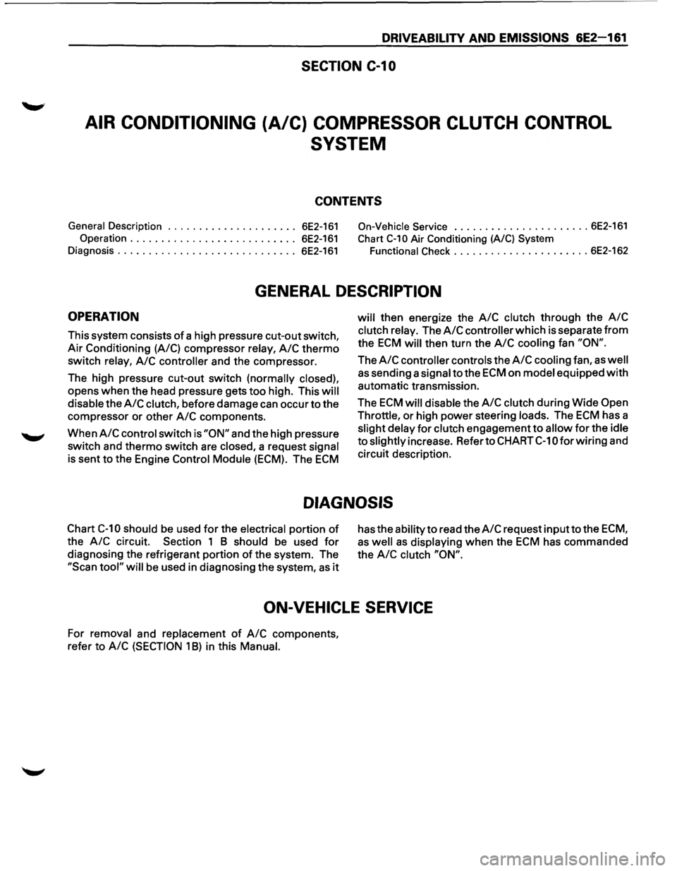
SECTION C-1 0
AIR CONDITIONING (A/C) COMPRESSOR CLUTCH CONTROL
SYSTEM
CONTENTS
General Description ..................... 6E2-161 On-Vehicle Service ...................... 6E2-161
Operation ........................... 6E2-161 Chart C-10 Air Conditioning (A/C) System
Diagnosis ............................. 6E2-161 Functional Check ...................... 6E2-162
GENERAL DESCRIPTION
OPERATION
This system consists of a high pressure cut-out switch,
Air Conditioning (A/C) compressor
relay, A/C thermo
switch relay, A/C controller and the compressor.
The high pressure cut-out switch
(normally closed),
opens when the head pressure gets too high. This will
disable
the A/C clutch, before damage can occur to the
compressor or other
A/C components.
When
A/C control switch is "ON" and the high pressure
switch and thermo switch are
closed, a request signal
is sent to the Engine Control Module (ECM). The ECM
will then energize the A/C clutch through the A/C
clutch relay. The A/C controller which is separate from
the ECM will then turn the A/C cooling fan "ON".
The A/C controller controls the A/C cooling fan, as well
as sending a signal to the ECM on model equipped with
automatic transmission.
The
ECM will disable the A/C clutch during Wide Open
Throttle,
or high power steering loads. The ECM has a
slight delay for clutch engagement to allow for the idle
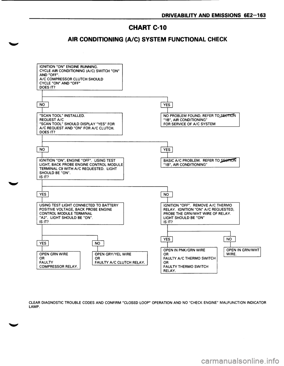
to slightly increase. Refer to CHART C-1 0 for wiring and
circuit description.
DIAGNOSIS
Chart C-10 should be used for the electrical portion of
the A/C circuit. Section 1 B should be used for
diagnosing the refrigerant portion of the system. The
"Scan tool" will be used in diagnosing the system, as it
has the ability to read the A/C request inputto the ECM,
as well as displaying when the ECM has commanded
the
A/C clutch "ON".
ON-VEHICLE SERVICE
For removal and replacement of A/C components,
refer to
A/C (SECTION 1 B) in this Manual.
Page 858 of 1928
6E2-162 DRIVEABILITY AND EMISSIONS
CHART C-10
AIR CONDITIONING (A/C) SYSTEM FUNCTIONAL CHECK
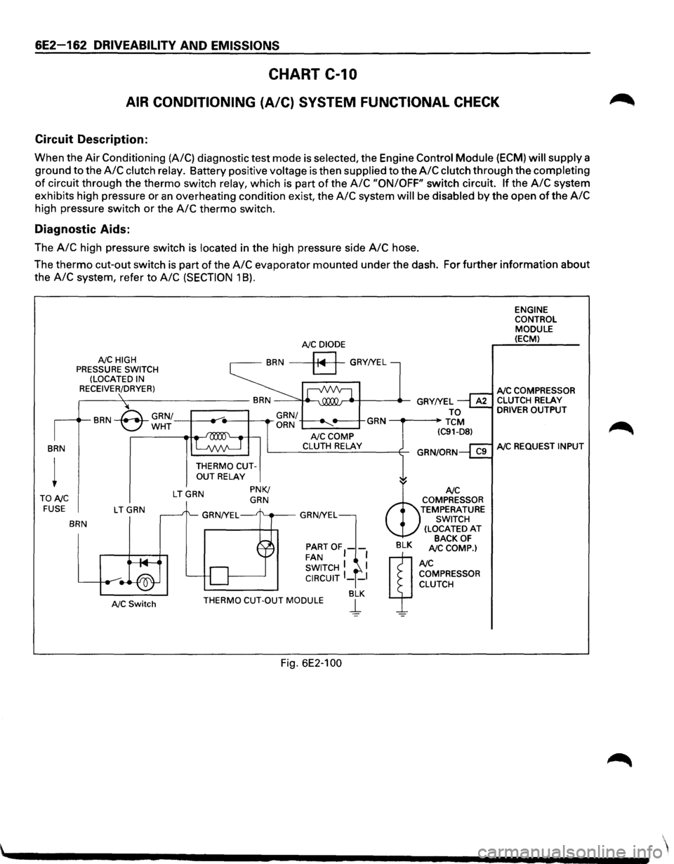
Circuit Description:
When the Air Conditioning (A/C) diagnostic test mode is selected, the Engine Control Module (ECM) will supply a
ground to the
A/C clutch relay. Battery positive voltage is then supplied to the A/C clutch through the completing
of circuit through the thermo switch relay, which is part of the A/C "ON/OFF" switch circuit. If the A/C system
exhibits high pressure or
an overheating condition exist, the A/C system will be disabled by the open of the A/C
high pressure switch or the A/C thermo switch.
Diagnostic Aids:
The A/C high pressure switch is located in the high pressure side A/C hose.
The
thermo cut-out switch is part of the A/C evaporator mounted under the dash. For further information about
the
A/C system, refer to A/C (SECTION 1 8).
BRN
TONC FUSE
NC HIGH
PRESSURE SWITCH
(LOCATED IN
RECEIVER/DRYER)
LTGRN
BRN
NC Switch
NC DIODE
BRN a GRY!YEL
THERMO CUTOUT RELAY
LTGRN PNK/ GRN
NCCOMP CLUTH RELAY
PARTOF1-FAN I SWITCH I I CIRCUIT I __ I
BLK THERMO CUT-OUT MODULE j_
Fig. 6E2-100
ENGINE
CONTROL
MODULE (ECM)
NC COMPRESSOR CLUTCH RELAY DRIVER OUTPUT
NC REQUEST INPUT
Page 859 of 1928
DRIVEABILITV AND EMISSIONS 6E2-163
CHART C-10
AIR CONDITIONING (A/C) SYSTEM FUNCTIONAL CHECK
IGNITION "ON" ENGINE RUNNING.
CYCLE AIR CONDITIONING (A/C) SWITCH "ON" AND "OFF". A/C COMPRESSOR CLUTCH SHOULD
CYCLE "ON" AND "OFF"
DOES IT?
$
$
"SCAN TOOL" INSTALLED.
NO PROBLEM FOUND, REFER TO)>e€TIO'N REQUEST A/C "1B", AIR CONDITIONING"
"SCAN TOOL" SHOULD DISPLAY "YES" FOR FOR SERVICE OF A/C SYSTEM A/C REQUEST AND "ON" FOR A/C CLUTCH.
DOES IT?
$
$
IGNITION "ON", ENGINE "OFF". USING TEST BASIC A/C PROBLEM. REFER TO~ LIGHT, BACK PROBE ENGINE CONTROL MODULE "1B", AIR CONDITIONING"
TERMINAL C9 WITH A/C REQUESTED. LIGHT
SHOULD BE "ON". IS IT?
$ $
USING TEST LIGHT CONNECTED TO BATTERY IGNITION "OFF". REMOVE A/C THERMO
POSITIVE VOLTAGE, BACK PROBE ENGINE RELAY. IGNITION "ON" A/C REQUESTED, CONTROL MODULE TERMINAL PROBE THE GRN/WHT WIRE OF RELAY. "A2". LIGHT SHOULD BE "ON". LIGHT SHOULD BE "ON" IS IT?
IS IT?
I
$ $
~ $ OPEN IN PNK/GRN WIRE I OPEN IN GRN/WHTJ OPEN GRN WIRE
OPEN GRY/YEL WIRE OR WIRE. OR OR FAULTY A/C THERMO SWITCH FAULTY FAULTY A/C CLUTCH RELAY. OR COMPRESSOR RELAY. FAULTY THERMO SWITCH RELAY.
CLEAR DIAGNOSTIC TROUBLE CODES AND CONFIRM "CLOSED LOOP" OPERATION AND NO "CHECK ENGINE" MALFUNCTION INDICATOR LAMP.
Page 860 of 1928
6E2 164 DRIVEABILITY AND EMISSIONS
SECTION C-13
POSITIVE CRANKCASE VENTILATION (PCV)
CONTENTS
GENERAL DESCRIPTION ................. 6E2-164 DIAGNOSIS ............................ 6E2-165
PCVValve .......................... 6E2-164 Functional Check of PCV ................ 6E2-165
Results of Incorrect Operation ............ 6E2-165
ON-VEHICLE SERVICE .................... 6E2-165
GENERAL DESCRIPTION
PCV VALVE
A Positive Crankcase Ventilation (PCV) system is used
to consume crankcase vapors in the combustion
process instead
of venting to atmosphere. Fresh air
from the throttle body is supplied to the crankcase,
mixed
with blow-by gases and then passed through a
Positive Crankcase Ventilation (PCV) into the intake
manifold.
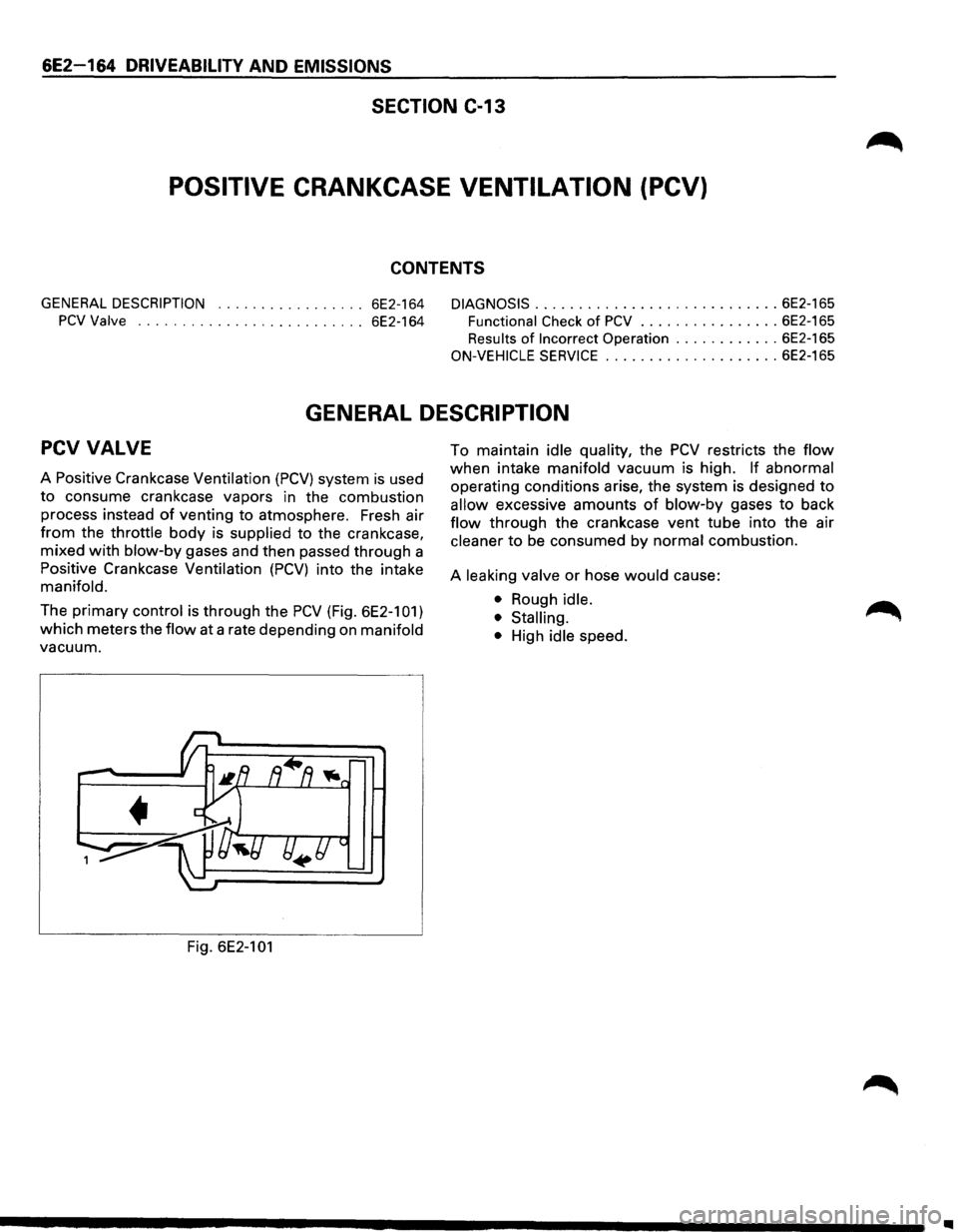
The primary control is through the PCV (Fig. 6E2-101)
which meters the
flow at a rate depending on manifold
vacuum.
Fig.
6E2-101
To maintain idle quality, the PCV restricts the flow
when intake manifold vacuum is high. If abnormal
operating conditions arise, the system is designed to
allow excessive amounts of blow-by gases to back
flow through the crankcase vent tube into the air
cleaner to be consumed by normal combustion.
A
leaking valve or hose would cause:
• Rough idle.
• Stalling.
•
High idle speed.
..