ISUZU TROOPER 1995 Workshop Manual
Manufacturer: ISUZU, Model Year: 1995, Model line: TROOPER, Model: ISUZU TROOPER 1995Pages: 1928
Page 831 of 1928
RESULTS OF INCORRECT OPERATION
Poor idle, stalling and poor driveability can be caused
by:
• Inoperative purge solenoid.
•
Damaged canister.
• Hoses split, cracked and/or not connected to the
proper tubes.
Evidence
of fuel loss or fuel vapor odor can be caused
by:
• Liquid fuel leaking from fuel lines, or fuel pump.
DRIVEABILITY AND EMISSIONS 6E2-135
• Cracked or damaged canister.
• Disconnected, misrouted, kinked, deteriorated or
damaged vapor hoses,
or control hoses.
If the solenoid is always open, the canister can purge to
the intake manifold at all times. This can allow extra
fuel at idle or during warm-up, which can cause rough
or unstable idle, or too rich operation.
If the solenoid is always closed, the canister can
become over-loaded,
resulting in fuel odor.
DIAGNOSIS
The evaporate em1ss1on canister purge solenoid
operation is covered in CHART C-3 at the end of this
section. VISUAL CHECK OF CANISTER
Cracked or damaged, replace canister.
FUEL VAPOR CANISTER
1••1 Remove or Disconnect
ON-VEHICLE SERVICE
CANISTER HOSES
1. Hoses from canister. Mark hoses to install on new
canister. Refer
to Vehicle Emission Control
Information label for
routing of canister hoses. When replacing hoses, use
6148M
or its equivalent.
2. Canister.
l••llnstall or Connect
1. Canister as removed.
2. Hoses. Make sure connetions are correct.
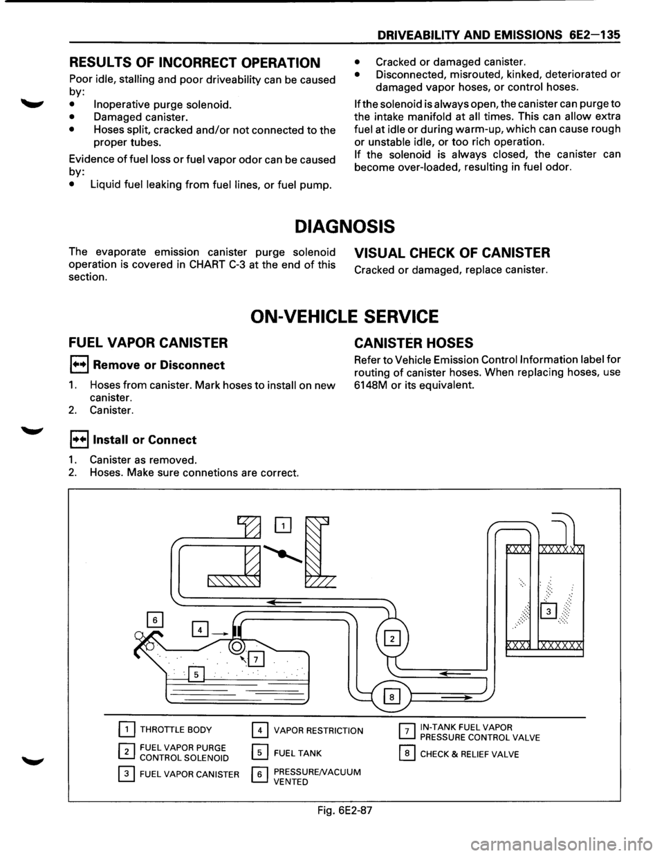
[2] THROTTLE BODY
r:l FUEL VAPOR PURGE ~ CONTROL SOLENOID
0 FUEL VAPOR CANISTER
0 VAPOR RESTRICTION
0 FUEL TANK
r.;;'l PRESSURENACUUM L....J VENTED
Fig. 6E2-87
r-:;-1 IN-TANK FUEL VAPOR ~ PRESSURE CONTROL VALVE
0 CHECK & RELIEF VALVE
Page 832 of 1928
6E2-136 DRIVEABILITY AND EMISSIONS
CHART C-3
EVAPORATIVE EMISSION CANISTER PURGE VALVE CHECK
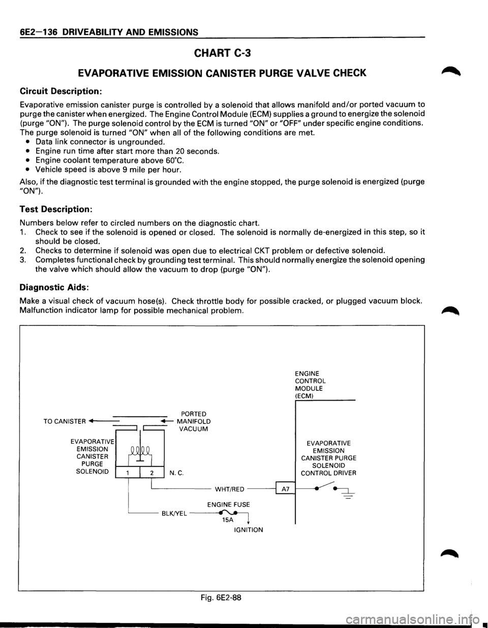
Circuit Description:
Evaporative emission canister purge is controlled by a solenoid that allows manifold and/or ported vacuum to
purge the canister when energized. The Engine Control Module (ECM) supplies a ground to energize the solenoid
(purge "ON"). The purge solenoid control by the ECM is turned "ON" or "OFF" under specific engine conditions.
The purge
solenoid is turned "ON" when all of the following conditions are met.
• Data link connector is ungrounded.
• Engine run time after start more than 20 seconds.
• Engine coolant temperature above 60°C.
• Vehicle speed is above 9 mile per hour.
Also, if the diagnostic test terminal is grounded with the engine stopped, the purge solenoid is energized (purge
"ON").
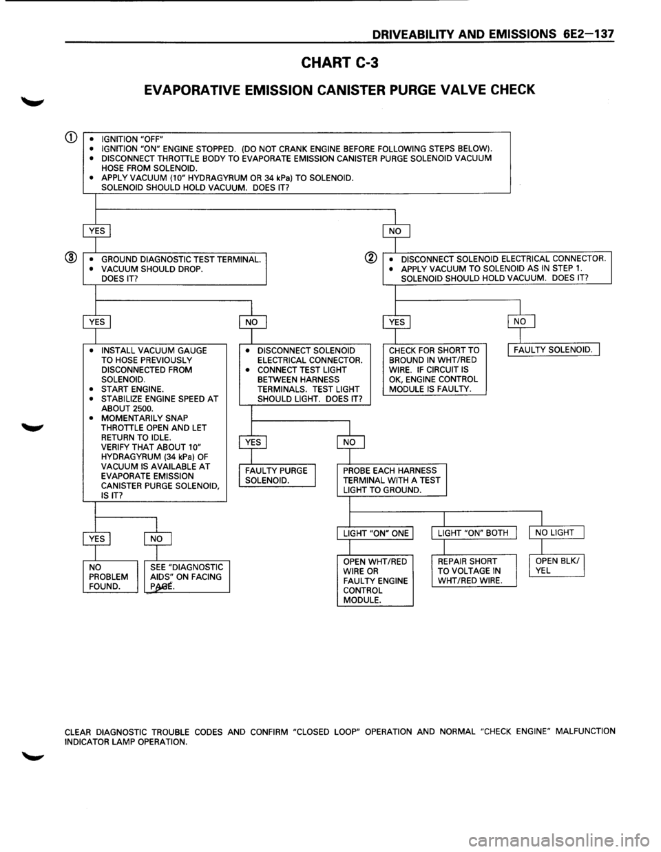
Test Description:
Numbers below refer to circled numbers on the diagnostic chart.
1. Check to see if the solenoid is opened or closed. The solenoid is normally de-energized in this step, so it
should be closed.
2. Checks to determine if solenoid was open due to electrical CKT problem or defective solenoid.
3. Completes functional check by grounding test terminal. This should normally energize the solenoid opening
the
valve which should allow the vacuum to drop (purge "ON").
Diagnostic Aids:
Make a visual check of vacuum hose(s). Check throttle body for possible cracked, or plugged vacuum block.
Malfunction
indicator lamp for possible mechanical problem.
EVAPORATIVE
EMISSION CANISTER
PURGE SOLENOID N.C.
L__ _____ WHT/RED -----;
ENGINE FUSE
BLKJYEL~ 15A ~
IGNITION
Fig. 6E2-88
ENGINE
CONTROL
MODULE (ECM)
EVAPORATIVE EMISSION
CANISTER
PURGE SOLENOID
CONTROL DRIVER
•
Page 833 of 1928
DRIVEABILITV AND EMISSIONS 6E2-137
CHART C-3
EVAPORATIVE EMISSION CANISTER PURGE VALVE CHECK
Q) • IGNITION "OFF"
• IGNITION "ON" ENGINE STOPPED. (DO NOT CRANK ENGINE BEFORE FOLLOWING STEPS BELOW).
• DISCONNECT THROTTLE BODY TO EVAPORATE EMISSION CANISTER PURGE SOLENOID VACUUM
HOSE FROM SOLENOID.
•
APPLY VACUUM (10" HYDRAGYRUM OR 34 kPa) TO SOLENOID.
SOLENOID SHOULD HOLD VACUUM. DOES IT?
~ $
• GROUND DIAGNOSTIC TEST TERMINAL. @ • DISCONNECT SOLENOID ELECTRICAL CONNECTOR. ® • VACUUM SHOULD DROP. • APPLY VACUUM TO
SOLENOID AS IN STEP 1. DOES IT? SOLENOID
SHOULD HOLD VACUUM. DOES IT?
I
$ $ $ $
• INSTALL VACUUM GAUGE • DISCONNECT SOLENOID CHECK FOR SHORT TO I FAULTY SOLENOID. J TO HOSE PREVIOUSLY ELECTRICAL CONNECTOR. BROUND IN WHT
/RED DISCONNECTED FROM
• CONNECT TEST LIGHT WIRE. IF CIRCUIT IS SOLENOID. BETWEEN HARNESS
OK,
ENGINE CONTROL
• START ENGINE. TERMINALS. TEST LIGHT MODULE IS FAULTY. •
STABILIZE ENGINE SPEED AT SHOULD LIGHT. DOES IT?
ABOUT 2500.
• MOMENTARILY SNAP
THROTTLE OPEN AND LET
$
RETURN TO IDLE.
~
VERIFY THAT ABOUT 10" HYDRAGYRUM (34 kPa) OF VACUUM IS AVAILABLE AT FAULTY PURGE I PROBE EACH HARNESS
EVAPORATE EMISSION
SOLENOID. TERMINAL WITH A TEST
CANISTER PURGE SOLENOID, LIGHT TO GROUND.
IS IT?
I I
$
$
LIGHT "ON" ONE LIGHT
"ON" BOTH I NO LIGHT J
I I
OPEN WHT/RED REPAIR SHORT I OPEN BLK/ I NO SEE "DIAGNOSTIC
WIRE OR TO VOLTAGE IN VEL PROBLEM ~~.ON FACING FAULTY ENGINE WHT/RED WIRE.
FOUND. p . CONTROL
MODULE.
CLEAR DIAGNOSTIC TROUBLE CODES AND CONFIRM "CLOSED LOOP" OPERATION AND NORMAL "CHECK ENGINE" MALFUNCTION
INDICATOR LAMP OPERATION.
Page 834 of 1928
6E2-138 DRIVEABILITY AND EMISSIONS
SECTION C4
ELECTRONIC IGNITION (EI) SYSTEM/IGNITION CONTROL (IC)
CONTENTS
General Description . . . . . . . . . . . . . . . . . . . . . 6E2-138
Purpose
............................ 6E2-138
Operation
........................... 6E2-138
Results of Incorrect Operation . . . . . . . . . . . 6E2-139
How diagnostic trouble code (DTC) 42 is
Determined ........................ 6E2-139
Diagnosis. . . . . . . . . . . . . . . ............. 6E2-139
Diagnostic
trouble code (DTC) 12 . . . . . . . . . 6E2-139
On-Vechicle Service . .
. . . . . . . . . . . . . . . . . . . 6E2-139
Electronic Ignition (EI) Assembly .......... 6E2-139
Crankshaft Position (CKP) Sensor ......... 6E2-140
Ignition Coil
.......................... 6E2-140
Ignition Control
Module (ICM) ............ 6E2-140
Ignition
Timing ....................... 6E2-140
Chart
C-4D-1 Electronic Ignition (EI) misfire
at
Idle .............................. 6E2-142
Chart C-4D-2 Electronic Ignition (EI) misfire
Under Load .......................... 6E2-144
GENERAL DESCRIPTION
PURPOSE
The Electronic Ignition (EI) system controls fuel
combustion by providing a spark to ignite the
compressed
air/fuel mixture at the correct time. To
provide improved engine performance,
fuel economy,
and
control of exhaust emissions, the Engine Control
Module
(ECM) controls spark advance timing with the
Ignition Control (IC) system.
OPERATION
The "EI" is a "waste spark" system in which 2 plugs are
fired
simultaneously from one coil. The spark plugs are
paired
to a coil, so that when both fire, one cylinder is
on the compression stroke and the other is on exhaust.
There is
Iitie resistance across the plug gap on the
exhaust stroke, so the
plug requires very little voltage
to fire, thereby providing the other plug (compression)
with maximum available voltage.
The system uses a magnetic Crankshaft Position (CKP)
sensor which protrudes into the block, within
approximately .050" of the crankshaft reluctor. The
reluctor is a special wheel cast on the crankshaft that
has seven machined
slots, six of which are equally
spaced 60° apart). The seventh slot is spaced 1 oo from
one
of the other slots. As the reluctor rotates with the
crankshaft, the
slots change the magnetic field of the
sensor, causing
an induced voltage pulse.
By counting the time between pulses, the Ignition
Control Module (ICM)
can recognize the pulse of the
seventh
slot (sync pulse). Based on this sync pulse, the
module sends the reference signal to the ECM to
calculate CKP (used to fire coils in correct sequence)
and engine speed.
To
properly control timing, the ECM relies on the
following information:
• Engine load (manifold absolute pressure or
vacuum).
• Atmospheric (barometric) pressure.
• Engine temperature.
• Intake air temperature.
• CKP
• Engine speed (revolution per minute).
The ignition
control system consisits of the "EI"
assembly (coils, module,
and CKP sensor), ECM and
connecting wires. These circuits
perform the following
functions:
• "EI" reference
The CKP sensor sends a signal to the ICM which
generates a reference
pulse which is sent to the
ECM. The ECM uses this signal to calculate CKP
and engine speed (also used to trigger the
injector).
• Reference ground (GND)
This wire is GNd through the module and makes
sure the GNd circuit has no
voltage drop between
the
ICM and the ECM, which if open, could affect
performance.
• Bypass
At about 400 revolution per minute, the ECM
applies 5 volts to this circuit to switch spark timing
control from the ICM to the ECM. An open or
grounded bypass circuit
will set a diagnostic
trouble code 42 and the engine will run at base
timing,
plus a small amount of advance built into
the
ICM.
• IGNITION CONTROL (IC)
The ECM uses this circuit (when bypass voltage is
applied) to trigger the "EI" module. The ECM uses
the
CKP to base its calculation of the amount of
spark advance needed under present engine
conditions.
•
Page 835 of 1928
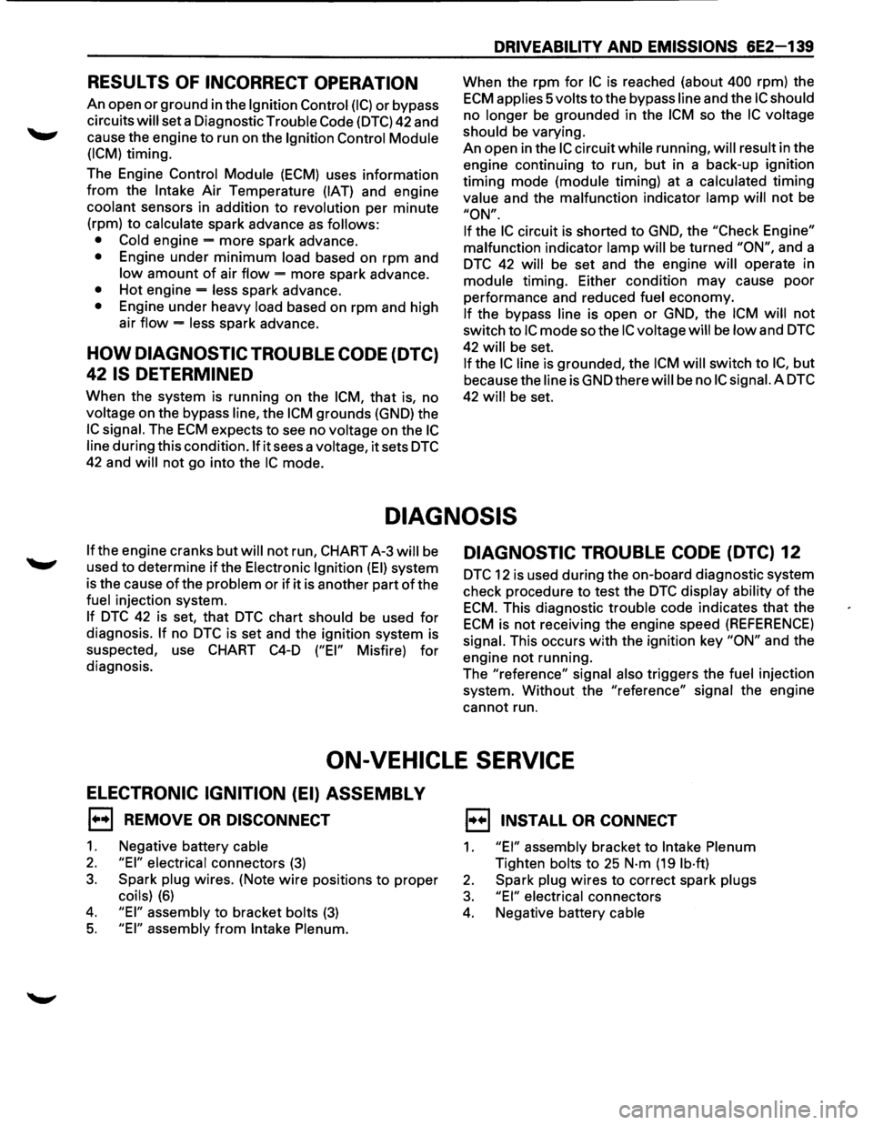
RESULTS OF INCORRECT OPERATION
An open or ground in the Ignition Control (I C) or bypass
circuits
will set a Diagnostic Trouble Code (DTC) 42 and
cause the engine
to run on the Ignition Control Module
(ICM)
timing.
The Engine
Control Module (ECM) uses information
from the Intake Air Temperature (IAT) and engine
coolant sensors in addition to revolution per minute
(rpm) to
calculate spark advance as follows:
• Cold
engine -more spark advance.
• Engine under minimum load based on rpm and
low amount of air flow = more spark advance.
• Hot engine = less spark advance.
• Engine under heavy load based on rpm and high
air
flow = less spark advance.
HOW DIAGNOSTIC TROUBLE CODE (DTC)
42 IS DETERMINED
When the system is running on the ICM, that is, no
voltage on the bypass line, the ICM grounds (GND) the
IC signal. The ECM expects to see no voltage on the IC
line during this condition.lf it sees a voltage, it sets DTC
42 and will not go into the IC mode.
DRIVEABILITY AND EMISSIONS 6E2-139
When the rpm for IC is reached (about 400 rpm) the
ECM applies 5 volts to the bypass line and the IC should
no longer be grounded in the ICM so the IC voltage
should
be varying.
An open in the
IC circuit while running, will result in the
engine continuing to run, but in a back-up
ig~it~on
timing mode (module timing) at a calculated t1mmg
value
and the malfunction indicator lamp will not be
"ON".
If
the IC circuit is shorted to GND, the "Check Engine"
malfunction
indicator lamp will be turned "ON", and a
DTC 42 will be set and the engine will operate in
module timing. Either condition may cause poor
performance and reduced
fuel economy.
If the bypass line is open or GND, the ICM will not
switch to IC mode so the IC voltage will be low and DTC
42 will be set.
If the IC line is grounded, the ICM will switch to IC, but
because the line isGNDtherewill be no ICsignai.A DTC
42 will be set.
DIAGNOSIS
If the engine cranks but will not run, CHART A-3 will be
used to determine if the Electronic Ignition (EI) system
is the cause
of the problem or if it is another part of the
fuel injection system.
If DTC 42 is set, that DTC chart should be used for
diagnosis. If no DTC is set and the ignition system is
suspected, use
CHART C4-D ("EI" Misfire) for
diagnosis.
DIAGNOSTIC TROUBLE CODE (DTC) 12
DTC 12 is used during the on-board diagnostic system
check procedure to test the
DTC display ability of the
ECM. This diagnostic trouble code indicates that the
ECM is not receiving the engine speed (REFERENCE)
signal. This occurs with the ignition key "ON" and the
engine not running.
The "reference"
signal also triggers the fuel injection
system.
Without the "reference" signal the engine
cannot run.
ON-VEHICLE SERVICE
ELECTRONIC IGNITION (EI) ASSEMBLY
1••1 REMOVE OR DISCONNECT
1. Negative battery cable
2. "EI" electrical connectors (3)
3. Spark plug wires. (Note wire positions to proper
coils) (6)
4. "EI" assembly to bracket bolts (3)
5. "EI" assembly from Intake Plenum.
1••1 INSTALL OR CONNECT
1. "EI" assembly bracket to Intake Plenum
Tighten bolts to 25 N·m (19 lb·ft)
2. Spark plug wires to correct spark plugs
3. "EI" electrical connectors
4. Negative battery cable
Page 836 of 1928
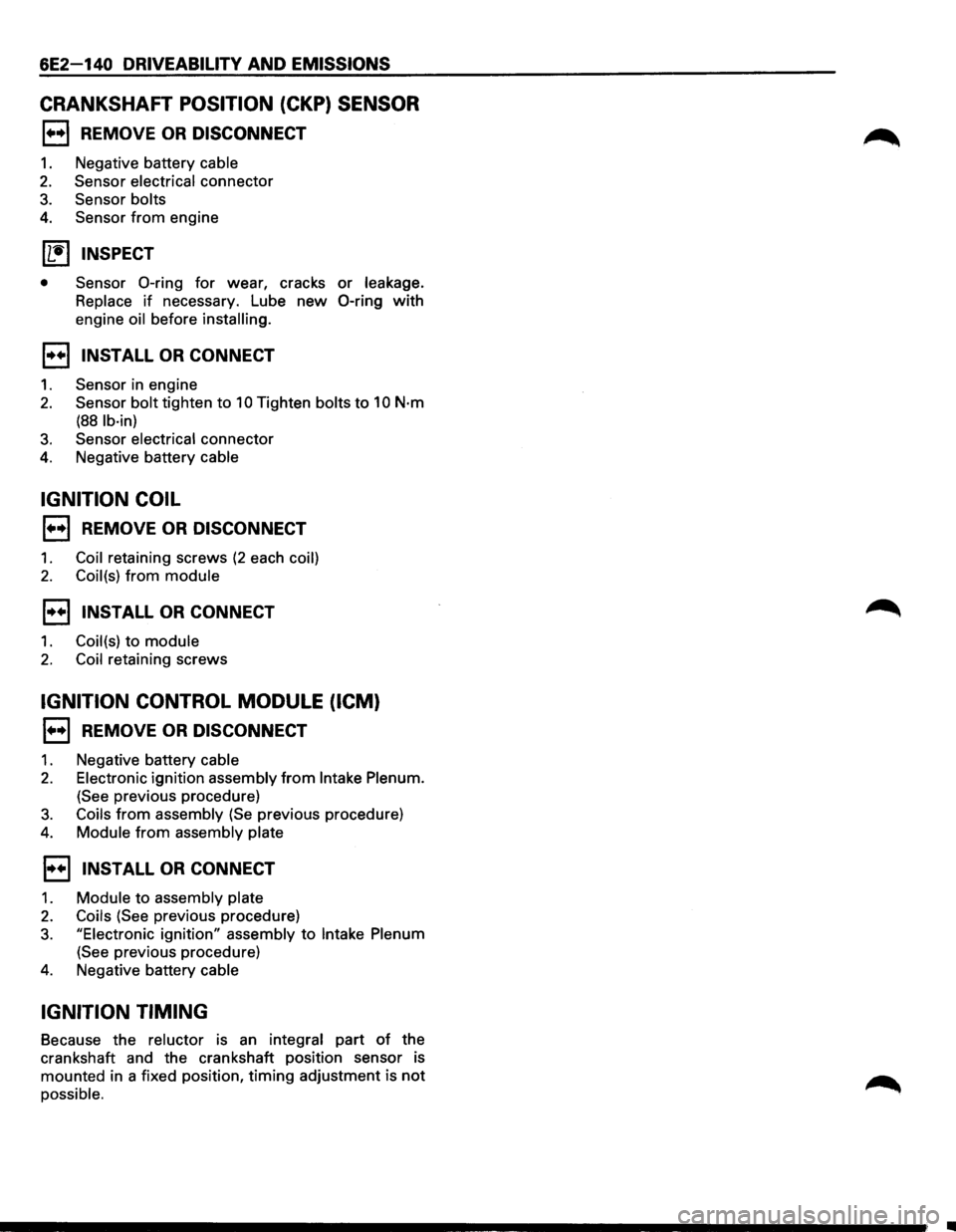
6E2-140 DRIVEABILITY AND EMISSIONS
CRANKSHAFT POSITION (CKP) SENSOR
1••1 REMOVE OR DISCONNECT
1. Negative battery cable
2. Sensor electrical connector
3. Sensor bolts
4. Sensor from engine
11!) INSPECT
• Sensor 0-ring for wear, cracks or leakage.
Replace
if necessary. Lube new 0-ring with
engine oil before installing.
1••1 INSTALL OR CONNECT
1. Sensor in engine
2. Sensor bolt tighten to 10 Tighten bolts to 10 N·m
(88 lb·in)
3. Sensor electrical connector
4. Negative battery cable
IGNITION COIL
1••1 REMOVE OR DISCONNECT
1. Coil retaining screws (2 each coil)
2. Coil(s) from module
1••1 INSTALL OR CONNECT
1. Coil(s) to module
2. Coil retaining screws
IGNITION CONTROL MODULE (ICM)
1••1 REMOVE OR DISCONNECT
1. Negative battery cable
2. Electronic ignition assembly from Intake Plenum.
(See previous procedure)
3. Coils from assembly (Se previous procedure)
4. Module from assembly plate
1••1 INSTALL OR CONNECT
1. Module to assembly plate
2. Coils (See previous procedure)
3. "Electronic ignition" assembly to Intake Plenum
(See previous procedure)
4. Negative battery cable
IGNITION TIMING
Because the reluctor is an integral part of the
crankshaft and the crankshaft position sensor is
mounted in a fixed position,
timing adjustment is not
possible .
........................................................................\
........ ;; .
Page 837 of 1928

DRIVEABILITY AND EMISSIONS 6E2-141
MEMO
-------·-----------·········--···\
············---------····\
··-·· .. --------···-··-------------------------------------------\
----····-----------------------------------------
Page 838 of 1928
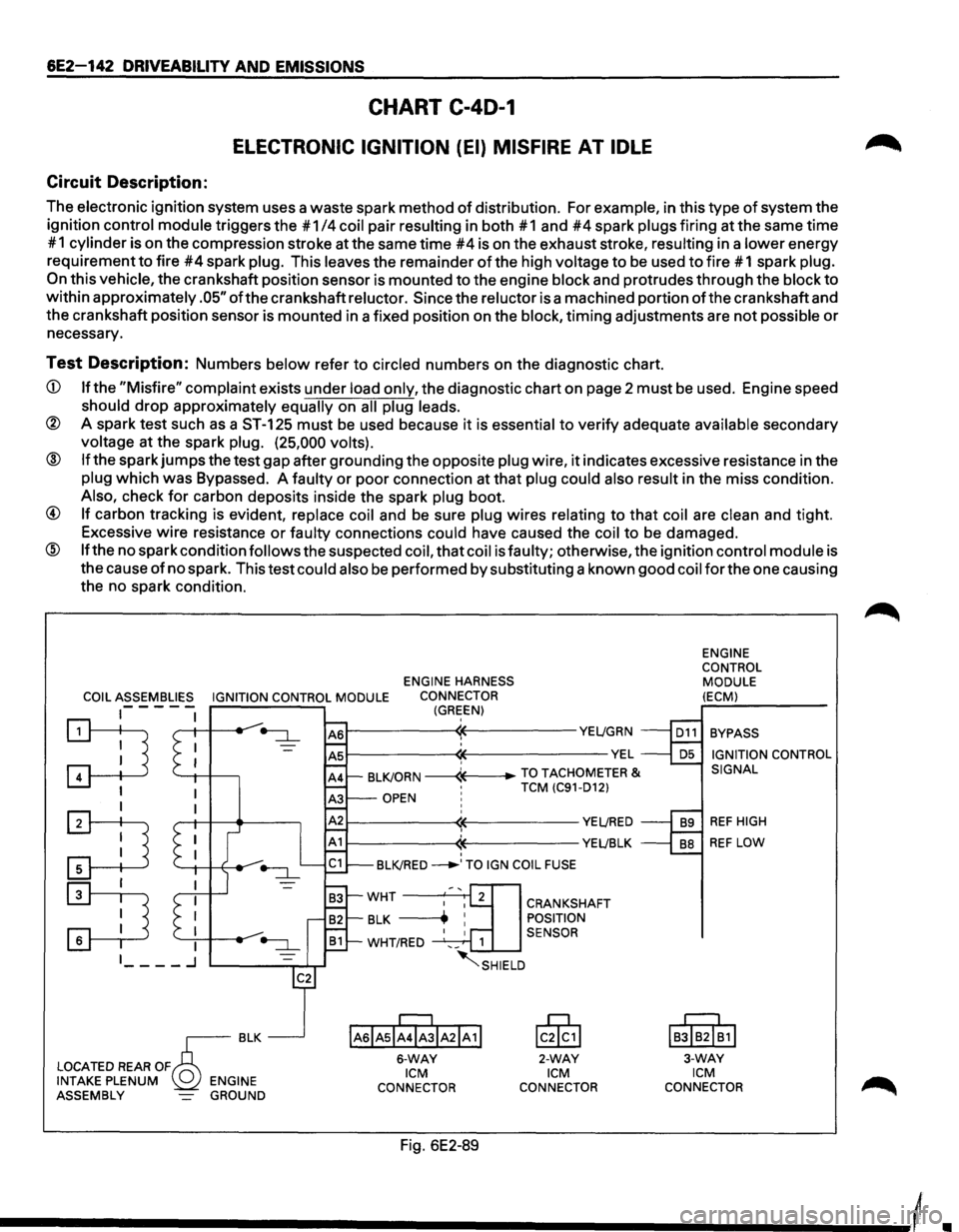
6E2-142 DRIVEABILITY AND EMISSIONS
CHART C-40-1
ELECTRONIC IGNITION (EI) MISFIRE AT IDLE
Circuit Description:
The electronic ignition system uses a waste spark method of distribution. For example, in this type of system the
ignition
control module triggers the #1 /4 coil pair resulting in both #1 and #4 spark plugs firing at the same time
# 1
cylinder is on the compression stroke at the same time #4 is on the exhaust stroke, resulting in a lower energy
requirement
to fire #4 spark plug. This leaves the remainder of the high voltage to be used to fire # 1 spark plug.
On this vehicle, the crankshaft position sensor is mounted to the engine block and protrudes through the block to
within approximately .05" ofthe crankshaft reluctor. Since the reluctor is a machined portion ofthe crankshaft and
the crankshaft position sensor is mounted in a fixed position on the
block, timing adjustments are not possible or
necessary.
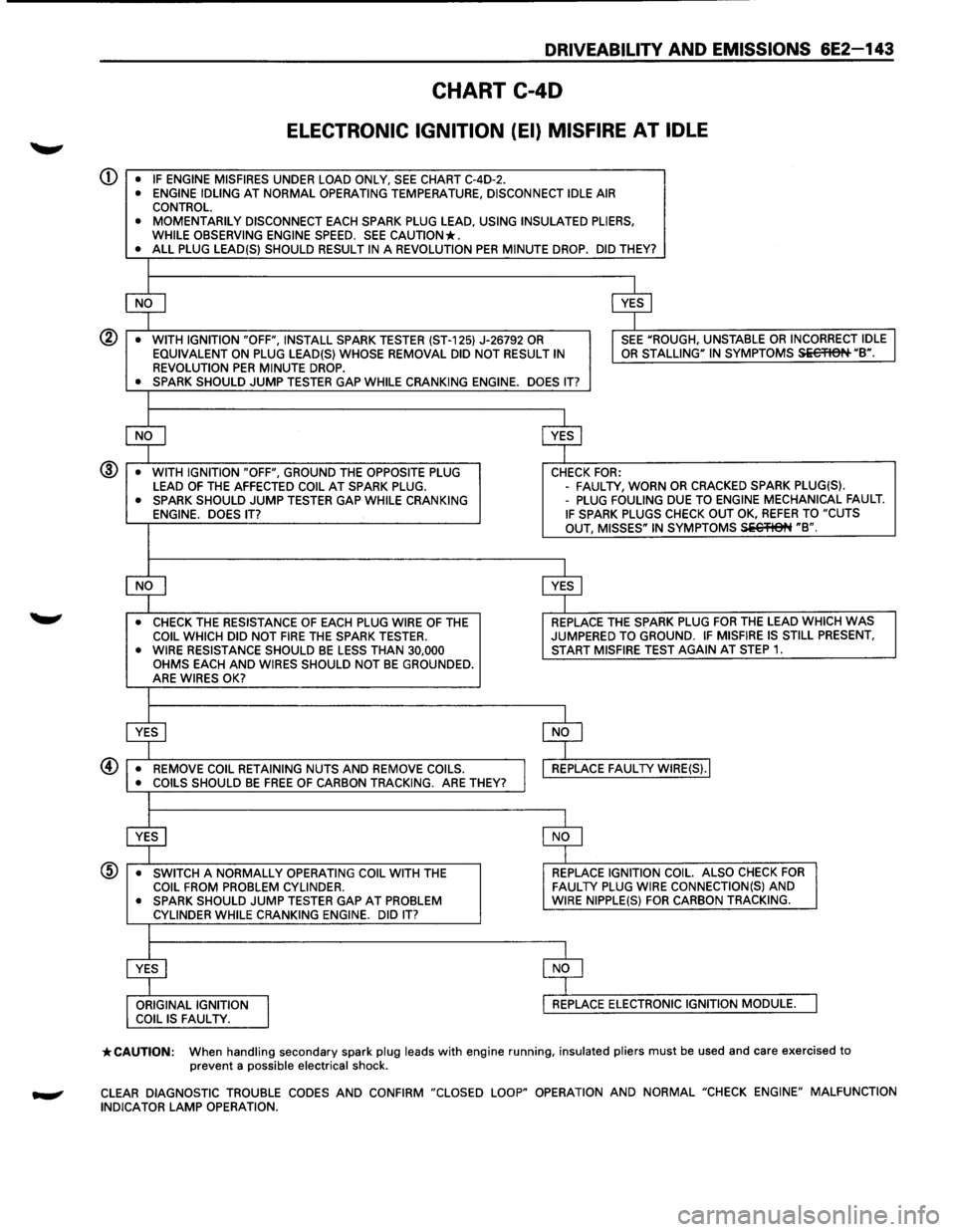
Test Description: Numbers below refer to circled numbers on the diagnostic chart.
CD If the "Misfire" complaint exists under load only, the diagnostic chart on page 2 must be used. Engine speed
should drop approximately equally on all plug leads.
® A spark test such as a ST-125 must be used because it is essential to verify adequate available secondary
voltage at the spark plug. (25,000 volts).
@ If the spark jumps the test gap after grounding the opposite plug wire, it indicates excessive resistance in the
plug which was Bypassed. A faulty or poor connection at that plug could also result in the miss condition.
Also, check for carbon deposits inside the spark plug boot.
@ If carbon tracking is evident, replace coil and be sure plug wires relating to that coil are clean and tight.
Excessive
wire resistance or faulty connections could have caused the coil to be damaged.
@ If the no spark condition follows the suspected coil, that coil is faulty; otherwise, the ignition control module is
the cause
of no spark. This test could also be performed by substituting a known good coil for the one causing
the no spark condition.
ENGINE HARNESS
COIL ASSEMBLIES IGNITION CONTROL MODULE CONNECTOR
1-- - - -(GREEN)
~ '--1-1 -+---,
I
:TI
:D
r---------~~----------YE~GRN
~--------~~-------------VEL ' BLKJORN -----4---+-TO TACHOMETER & •
TCM (C91-D12) OPEN ! ' r---------~~----------YE~RED
r-----------<1~----------YEL!BLK ' BLKJRED ___..,TO IGN COIL FUSE
IAsiAsl;rJIA21A 1!
6-WAY ICM
CONNECTOR
Fig. 6E2-89
CRANKSHAFT
POSITION
SENSOR
lc0§,1
2-WAY ICM
CONNECTOR ENGINE
CONTROL
MODULE
(ECM)
BYPASS IGNITION CONTROL
SIGNAL
REF HIGH
REF LOW
IB!IB2I~1I
3-WAY ICM CONNECTOR
Page 839 of 1928
DRIVEABILITV AND EMISSIONS 6E2-143
CHART C-40
ELECTRONIC IGNITION (EI) MISFIRE AT IDLE
CD • IF ENGINE MISFIRES UNDER LOAD ONLY, SEE CHART C-4D-2. • ENGINE IDLING AT NORMAL OPERATING TEMPERATURE, DISCONNECT IDLE AIR CONTROL. • MOMENTARILY DISCONNECT EACH SPARK PLUG LEAD, USING INSULATED PLIERS,
WHILE OBSERVING ENGINE SPEED. SEE CAUTION*. • ALL PLUG LEAD(S) SHOULD RESULT IN A REVOLUTION PER MINUTE DROP. DID THEY?
$ $
•
WITH IGNITION "OFF", INSTALL SPARK TESTER (ST-125) J-26792 OR I SEE "ROUGH, UNSTABLE OR INCORRECT IDLE
EQUIVALENT ON PLUG LEAD(S) WHOSE REMOVAL DID NOT RESULT IN OR STALLING" IN SYMPTOMS Si€'FISN "B". REVOLUTION PER MINUTE DROP. • SPARK SHOULD JUMP TESTER GAP WHILE CRANKING ENGINE. DOES IT?
$ $
•
WITH IGNITION "OFF", GROUND THE OPPOSITE PLUG CHECK FOR: @
LEAD OF THE AFFECTED COIL AT SPARK PLUG. -
FAUL TV, WORN OR CRACKED SPARK PLUG(S). • SPARK SHOULD JUMP TESTER GAP WHILE CRANKING -PLUG FOULING DUE TO ENGINE MECHANICAL FAULT. ENGINE. DOES IT? IF SPARK PLUGS CHECK OUT OK, REFER TO "CUTS
OUT, MISSES" IN SYMPTOMS SiC'flet~ "B".
~ $
• CHECK THE RESISTANCE OF EACH PLUG WIRE OF THE REPLACE
THE SPARK PLUG FOR THE LEAD WHICH WAS COIL WHICH DID NOT FIRE THE SPARK TESTER. JUMPERED TO GROUND. IF MISFIRE
IS STILL PRESENT, • WIRE RESISTANCE SHOULD BE LESS THAN 30,000 START MISFIRE TEST AGAIN AT STEP 1. OHMS EACH AND WIRES SHOULD NOT BE GROUNDED.
ARE WIRES OK?
$ $
• REMOVE COIL RETAINING NUTS AND REMOVE COILS.
I
REPLACE FAUL TV WIRE(S).I
• COILS SHOULD BE FREE OF CARBON TRACKING. ARE THEY?
$ $
•
SWITCH A NORMALLY OPERATING COIL WITH THE REPLACE IGNITION
COIL. ALSO CHECK FOR COIL FROM PROBLEM CYLINDER. FAULTY PLUG WIRE CONNECTION(S) AND • SPARK SHOULD JUMP TESTER GAP AT PROBLEM WIRE NIPPLE(S) FOR CARBON TRACKING.
CYLINDER WHILE CRANKING ENGINE. DID IT?
$ $
ORIGINAL IGNITION
I
REPLACE ELECTRONIC IGNITION MODULE. COIL IS FAUL TV.
*CAUTION: When handling secondary spark plug leads with engine running, insulated pliers must be used and care exercised to
prevent a possible electrical shock.
CLEAR DIAGNOSTIC TROUBLE CODES AND CONFIRM "CLOSED LOOP" OPERATION AND NORMAL "CHECK ENGINE" MALFUNCTION
INDICATOR LAMP OPERATION.
Page 840 of 1928
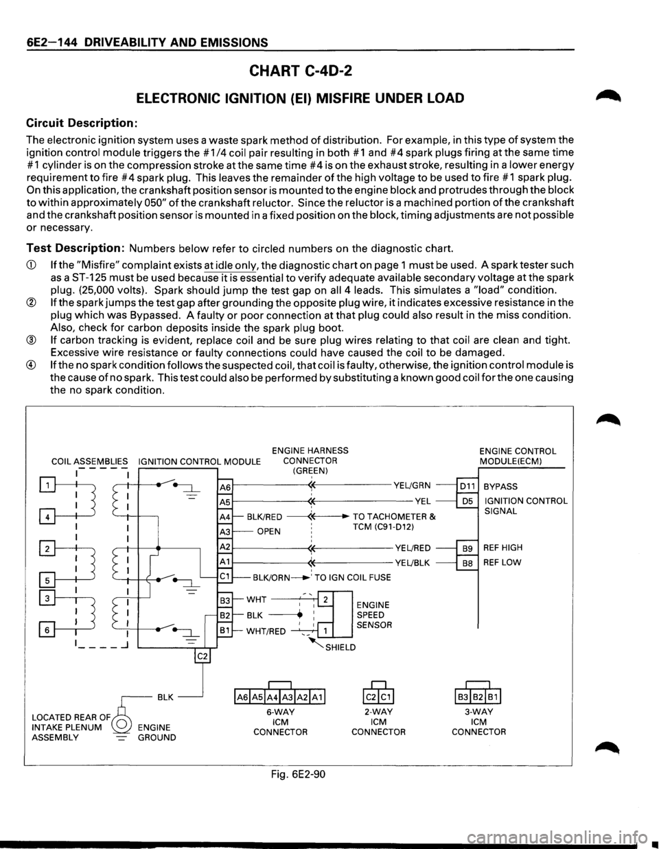
6E2-144 DRIVEABILITY AND EMISSIONS
CHART C-40-2
ELECTRONIC IGNITION (EI) MISFIRE UNDER LOAD
Circuit Description:
The electronic ignition system uses a waste spark method of distribution. For example, in this type of system the
ignition
control module triggers the # 1/4 coil pair resulting in both # 1 and #4 spark plugs firing at the same time
# 1 cylinder is on the compression stroke at the same time #4 is on the exhaust stroke, resulting in a lower energy
requirement
to fire #4 spark plug. This leaves the remainder of the high voltage to be used to fire #1 spark plug.
On this application, the crankshaft position sensor is mounted to the engine block and protrudes through the block
to within approximately 050" of the crankshaft reluctor. Since the reluctor is a machined portion of the crankshaft
and the crankshaft position sensor is mounted in a fixed position on the
block, timing adjustments are not possible
or necessary.
Test Description: Numbers below refer to circled numbers on the diagnostic chart.
CD If the "Misfire" complaint exists at idle only, the diagnostic chart on page 1 must be used. A spark tester such
as a ST-125 must be used because it is essential to verify adequate available secondary voltage at the spark
plug. (25,000 volts). Spark should jump the test gap on all 4 leads. This simulates a "load" condition.
® If the spark jumps the test gap after grounding the opposite plug wire, it indicates excessive resistance in the
plug which was Bypassed. A faulty or poor connection at that plug could also result in the miss condition.
Also, check for carbon deposits inside the spark plug boot.
® If carbon tracking is evident, replace coil and be sure plug wires relating to that coil are clean and tight.
Excessive
wire resistance or faulty connections could have caused the coil to be damaged.
® If the no spark condition follows the suspected coil, that coil is faulty, otherwise, the ignition control module is
the cause
of no spark. This test could also be performed by substituting a known good coil for the one causing
the no spark condition.
COIL ASSEMBLIES IGNITION CONTROL MODULE
ENGINE HARNESS
CONNECTOR
(GREEN) -----
:TI '--+I -l-----,
I
:TI
~
~--------~~-----------YE~GRN
~--------~~--------------VEL ' BLK/RED ------«--TO TACHOMETER &
OPEN ' TCM (C91-D12)
~--------~~-----------YE~RED
1------------((-----------YE~BLK ' BLK/ORN_.' TO IGN COIL FUSE
ENGINE SPEED
1 SENSOR
~SHIELD
IAsiAsii4ibiA21A11
6-WAY ICM
CONNECTOR
Fig. 6E2-90
lcik,l
2-WAY ICM
CONNECTOR ENGINE
CONTROL
MODULE(ECM)
BYPASS
IGNITION CONTROL
SIGNAL
REF HIGH
REF LOW
I
BJIB2I~1I
3-WAY ICM
CONNECTOR
•