ISUZU TROOPER 1995 Workshop Manual
Manufacturer: ISUZU, Model Year: 1995, Model line: TROOPER, Model: ISUZU TROOPER 1995Pages: 1928
Page 861 of 1928
DRIVEABILITV AND EMISSIONS 6E2-165
DIAGNOSIS
FUNCTIONAL CHECK OF POSITIVE
CRANKCASE VENTILATION (PCV)
If an engine is idling rough, check for a clogged PCV or
plugged hose. Replace as required. Use the following
procedure.
1. Remove PCV from rocker arm cover.
2. Run the engine at idle.
3. If there is no vacuum at valve, check for plugged
hoses or manifold port, or PCV.
Replace plugged or deteriorated hoses.
4. Stop the engine and remove PCV. Remove
PCV hose. Inspect metered orifice for being
restricted or
plugged. If restricted clean orifice.
With this system, any
blow-by in excess of the system
capacity (from a
badly-worn engine, sustained heavy
load, etc.) is exhausted into the intake manifold and is
drawn into the engine. Proper
operation
of the PCV System is dependent
upon a
sealed engine. If oil sledging or dilution is
noted, and the PCV System is functioning properly,
malfunction
indicator lamp for possible cause and
correct to ensure that system
will function as intended.
RESULTS OF INCORRECT OPERATION
A plugged valve or hose may cause:
• Rough idle.
• Stalling
or slow idle speed.
• Oil leaks.
• Oil
in air cleaner.
• Sludge
in engine.
ON-VEHICLE SERVICE
An engine which is operated without any crankcase
ventilation can be damaged. Periodically, inspect the
PCV, hoses
and clamps and replace any showing
signs
of deterioration.
Page 862 of 1928
6E2-166 DRIVEABILITY AND EMISSIONS
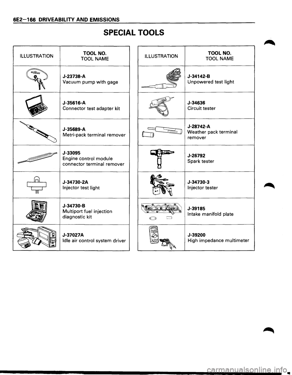
SPECIAL TOOLS
ILLUSTRATION TOOL NO.
TOOL NAME ILLUSTRATION
~
J-23738-A
Vacuum pump with gage
~
J-35616-A
Connector test adapter kit
'
J-35689-A
Metri-pack terminal remover
~
J-33095
Engine control module
connector terminal remover
$
J-34730-2A
Injector test light
•
J-34730-B
Multipart fuel injection
diagnostic kit
~~~ J-37027A
~~~
Idle air control system driver
TOOL NO.
TOOL NAME
J-34142-B
Unpowered test light
J-34636
Circuit tester
J-28742-A
Weather pack terminal
remover
J-26792
Spark tester
J-34730-3
Injector tester
J-39185
Intake manifold plate
J-39200
High impedance multimeter
..
Page 863 of 1928
ENGINE EXHAUST (V6 3.2L) 6F-1
SECTION 6F
ENGINE EXHAUST (V6 3.2L)
\fl CAUTION:
VI Exhaust system components must have enough clearance from the upderbody to prevent overheating the
floor pan and damaging the passenger compartment, insulation
and trim materials.
CONTENTS
General Description . . . . . . . . . . . . . . . . . . . . 6F,....1
Hangers ........................... , ... ..-6f-2
Three Way Catalytic Converter ....• ·; ~. 6F-2
Gasket . . . . . . . . . . . . . . . . . . . . . . . . . . . . . 6F-2
On-Vehicle Service ........ , . . . . . . . . . . . 6F-3
Front Exhaust Pipe ... , " ;< . . . . . . . . . . . . 6F-3
Center Exhaust Pipe.. .. : -. . . . . . . . . . . . . . . . 6F-4
.. .r·
Three Way Catalytic Converter . . . . . . . . . 6F-5
Pre Catalytic Converter . . . . . . . . . . . . . . . 6F-6
Exhaust Silencer . . . . . . . . . . . . . . . . . . . . . 6F-7
Rear Exhaust Pipe . . . . . . . . . . . . . . . . . . . . 6F-8
Exhaust Pipe Mounting Rubber . . . . . . . . 6F-9
Main Data and Specifications ........... 6F-10
Torque Specifications ............... 6F-10
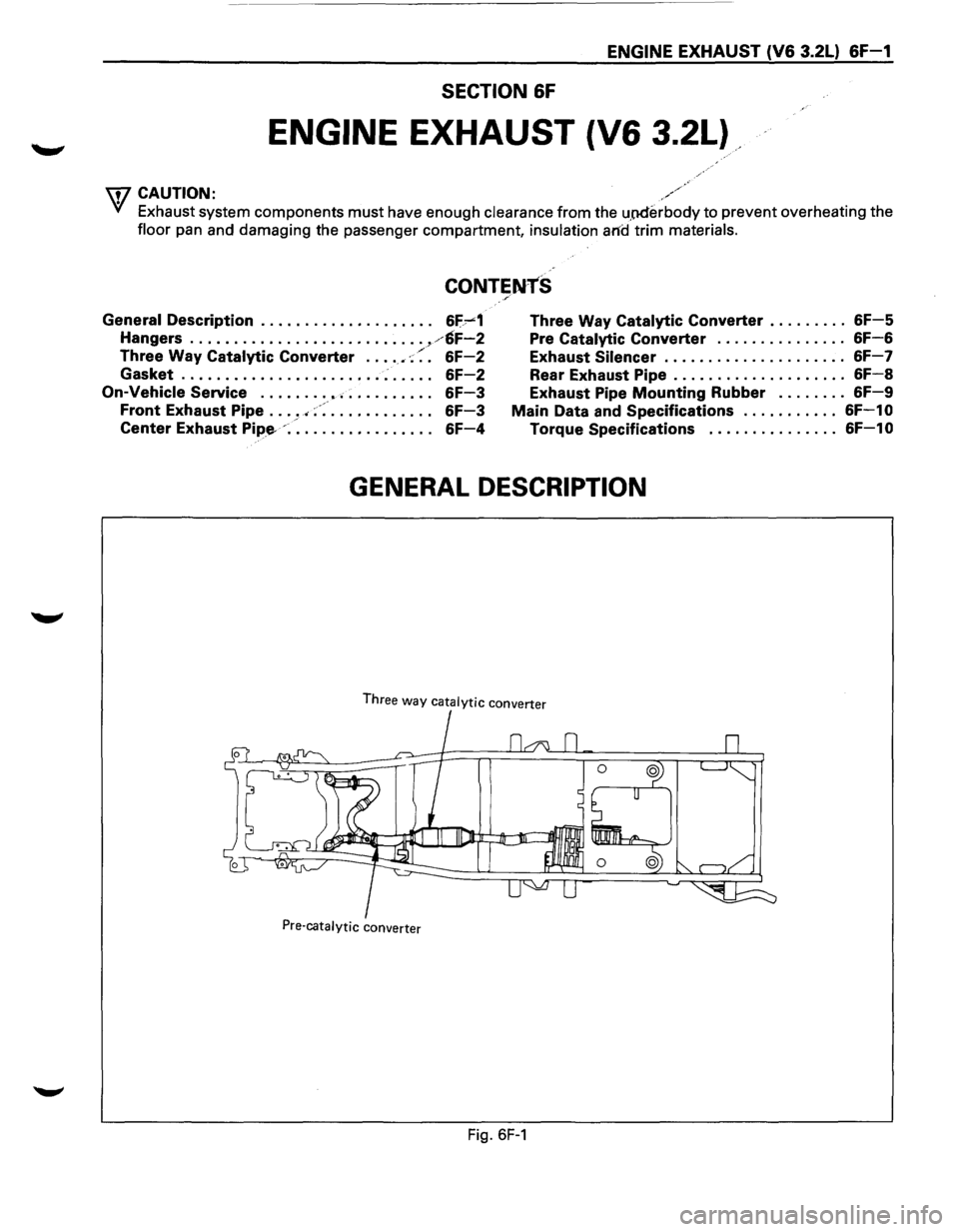
GENERAL DESCRIPTION
Three way catalytic converter
Pre-catalytic converter
Fig. 6F-1
Page 864 of 1928
6F-2 ENGINE EXHAUST (V6 3.2L)
When inspecting or replacing exhaust system
components, make sure there is adequate
clearance
from all points on the underbody to prevent over
heating the
floor pan and possible damage to the
passenger
compartment insulation and trim materials.
Check complete exhaust system and nearby body
areas and rear compartment lid for broken, damaged,
missing
or mispositioned parts, open seams, holes,
loose
connections or other deterioration which could
permit exhaust fumes to seep into the rear
compartment or passenger compartment. Dust or
water in the rear compartment may be an indication of
a problem in one of these areas. Any faulty areas
should be corrected immediately.
HANGERS
Various types of hangers are used to support exhaust
system(s). These
include conventional rubber straps,
rubber rings, and rubber
blocks.
The installation of exhaust system supports is very
important,
as improperly installed supports can cause
annoying vibrations
which can be difficult to diagnose.
THREE WAY CATAL VTIC CONVERTER
The three way catalytic converter is an emission
control device added to the exhaust system to reduce
pollutants from the exhaust gas stream.
W CAUTION:
VI • The catalytic converter requires the use of
unleaded fuel only.
Periodic
maintenance of the exhaust system is not
required. If the vehicle is raised for other service, it is
advisable to check the condition of the complete
exhaust system.
A
dual bed monolith catalytic converter is used in
combination
with three way catalytic converter.
Catalytic Types:
Three
way (Reduction/Oxidation) catalyst
The catalyst coating on the three way (reduction)
converter contains
platinum and rhodium which
lowers the levels of oxide of nitrogen (NOx) as well as
hydrocarbons (HC) and carbon monoxide (Co).
GASKET
The gasket must be replaced whenever a new exhaust
pipe,
muffler or catalytic converter is installed.
Page 865 of 1928
ENGINE EXHAUST (V6 3.2L) &F-3
ON-VEHICLE SERVICE
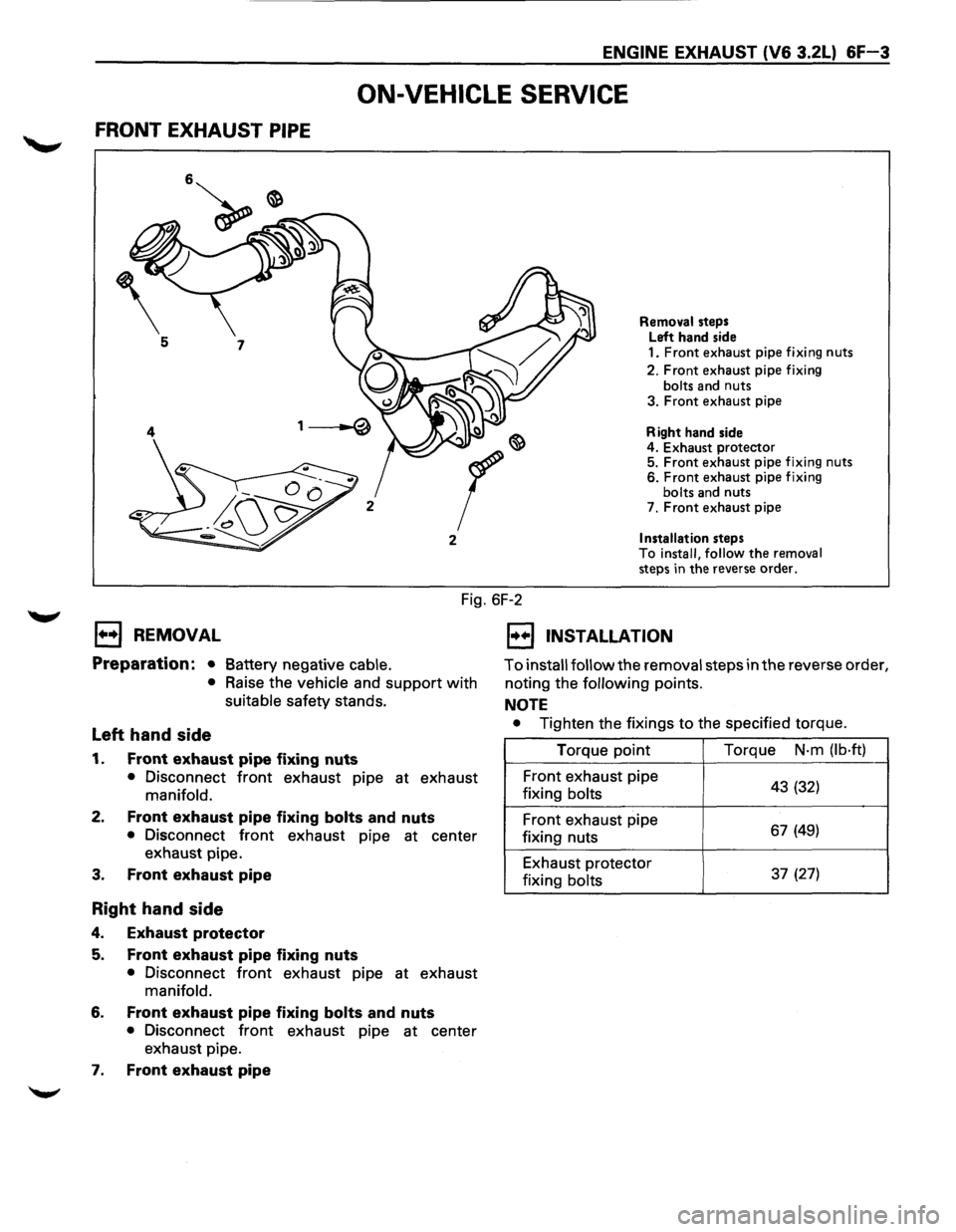
FRONT EXHAUST PIPE
2
Removal steps
Left hand side
1.
Front exhaust pipe fixing nuts
2. Front exhaust pipe fixing
bolts and nuts
3. Front exhaust pipe
Right hand side
4. Exhaust
protector 5. Front exhaust pipe fixing nuts 6. Front exhaust pipe fixing bolts and nuts
7. Front exhaust pipe
Installation steps
To install, follow the removal steps in the reverse order.
Fig. 6F-2
EJ REMOVAL
Preparation: • Battery negative cable.
•
Raise the vehicle and support with
suitable safety stands.
Left hand side
1. Front exhaust pipe fixing nuts
• Disconnect front exhaust pipe at exhaust
manifold.
2. Front exhaust pipe fixing bolts and nuts
• Disconnect front exhaust pipe at center
exhaust pipe.
3.
Front exhaust pipe
Right hand side
4. Exhaust protector
5. Front exhaust pipe fixing nuts
• Disconnect front exhaust pipe at exhaust
manifold.
6. Front exhaust pipe fixing bolts and nuts
• Disconnect front exhaust pipe at center
exhaust pipe.
1. Front exhaust pipe
1•+1 INSTALLATION
To install follow the removal steps in the reverse order,
noting the
following points.
NOTE
• Tighten the fixings to the specified torque.
Torque point Torque
N·m (lb·ft)
Front exhaust pipe
43 (32) fixing bolts
Front exhaust pipe 67 (49) fixing nuts
Exhaust protector
37 (27) fixing bolts
Page 866 of 1928
&F-4 ENGINE EXHAUST (V6 3.2L)
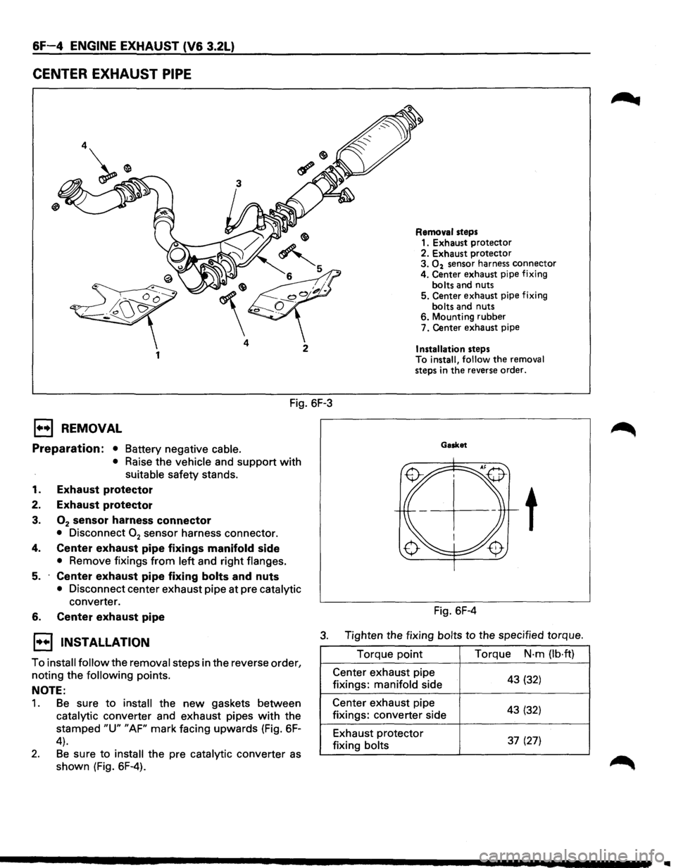
CENTER EXHAUST PIPE
4
1
Fig. 6F-3
E3 REMOVAL
Preparation: • Battery negative cable.
• Raise the vehicle and support with
suitable safety stands.
1. Exhaust protector
2. Exhaust protector
3. 02 sensor harness connector
• Disconnect 02 sensor harness connector.
4. Center exhaust pipe fixings manifold side
• Remove fixings from left and right flanges.
5. Center exhaust pipe fixing bolts and nuts
• Disconnect center exhaust pipe at pre catalytic
converter.
6. Center exhaust pipe
Removal steps 1. Exhaust protector
2. Exhaust protector
3.
02 sensor harness connector
4. Center exhaust pipe fixing
bolts and nuts
5. Center exhaust pipe fixing
bolts and nuts
6. Mounting rubber
7. Center exhaust pipe
Installation steps
To install, follow the removal
steps in the reverse order.
Gasket
t
Fig. 6F-4
1••1 INSTALLATION 3. Tighten the fixing bolts to the specified torque.
To
install follow the removal steps in the reverse order,
noting the
following points.
NOTE:
1. Be sure to install the new gaskets between
catalytic converter and exhaust pipes
with the
stamped
"U" "AF" mark facing upwards (Fig. 6F-
4).
2. Be sure to install the pre catalytic converter as
shown (Fig. 6F-4). Torque
point
Center exhaust pipe
fixings: manifold side
Center exhaust pipe
fixings: converter side
Exhaust protector
fixing bolts Torque
N·m
(lb·ft)
43 (32)
43 (32)
37 (27)
Page 867 of 1928
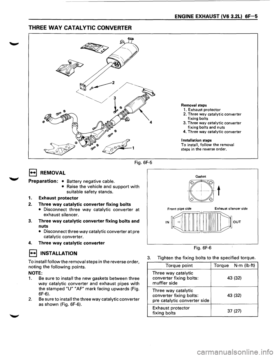
THREE WAY CATALYTIC CONVERTER
Fig. 6F-5
1••1 REMOVAL
Preparation: • Battery negative cable.
•
Raise the vehicle and support with
suitable safety stands.
1. Exhaust protector
2. Three way catalytic converter fixing bolts
• Disconnect three way catalytic converter at
exhaust
silencer.
3. Three way catalytic converter fixing bolts and
nuts
• Disconnect three way catalytic converter at pre
catalytic converter.
4. Three way catalytic converter
ENGINE EXHAUST (V6 3.2L) &F-5
Removal steps
1. Exhaust protector
2. Three way catalytic converter
fixing
bolts 3. Three way catalytic converter
fixing bolts and nuts
4. Three way catalytic converter
Installation steps
To
install, follow the removal steps in the reverse order.
Gasket
t
Front pipe side Exhaust silencer side
--;::;;;=;;:::;;=;;:::;;±:;;:~mn=i:'--
IN OUT
Fig. 6F-6
1••1 INSTALLATION
To install follow the removal steps in the reverse order,
noting the
following points.
3. Tighten the fixing bolts to the specified torque.
NOTE:
1. Be sure to install the new gaskets between three
way catalytic converter and exhaust pipes with
the stamped "U" "AF" mark facing upwards (Fig.
6F-6).
2. Be sure to install the three way catalytic converter
as shown (Fig. 6F-6). Torque
point
Three way catalytic
converter
fixing bolts:
muffler side
Three
way catalytic
converter fixing bolts:
pre catalytic converter side
Exhaust protector
fixing
bolts
Torque N·m (lb·ft)
43 (32)
43 (32)
37
(27)
Page 868 of 1928
6F-6 ENGINE EXHAUST (V6 3.2L)
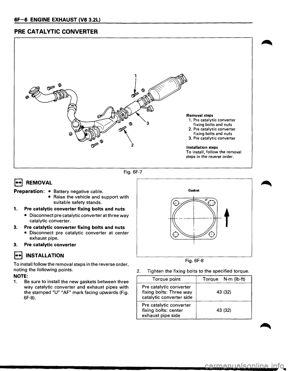
PRE CATAL VTIC CONVERTER
2
Fig. 6F-7
1••1 REMOVAL
Preparation: • Battery negative cable.
•
Raise the vehicle and support with
suitable safety stands.
1. Pre catalytic converter fixing bolts and nuts
• Disconnect pre catalytic converter at three way
catalytic converter.
3. Pre catalytic converter fixing bolts and nuts
• Disconnect pre catalytic converter at center
exhaust pipe.
3. Pre catalytic converter
1••1 INSTALLATION
Removal steps
1. Pre catalytic converter
fixing bolts and nuts
2. Pre catalytic converter
fixing bolts and
nuts 3. Pre catalytic converter
Installation steps To install, follow the removal
steps in the reverse order.
Gasket
t
Fig. 6F-8
To install follow the removal steps in the reverse order,
noting the following points. 2. Tighten the fixing bolts to the specified torque.
NOTE:
1. Be sure to install the new gaskets between three
way catalytic converter and exhaust pipes with
the stamped "U" "AF" mark facing upwards (Fig.
6F-8). Torque
point
Pre catalytic converter
fixing
bolts: Three way
catalytic converter side
Pre catalytic converter
fixing
bolts: center
exhaust pipe side Torque
N·m
(lb·ft)
43 (32)
43 (32)
Page 869 of 1928
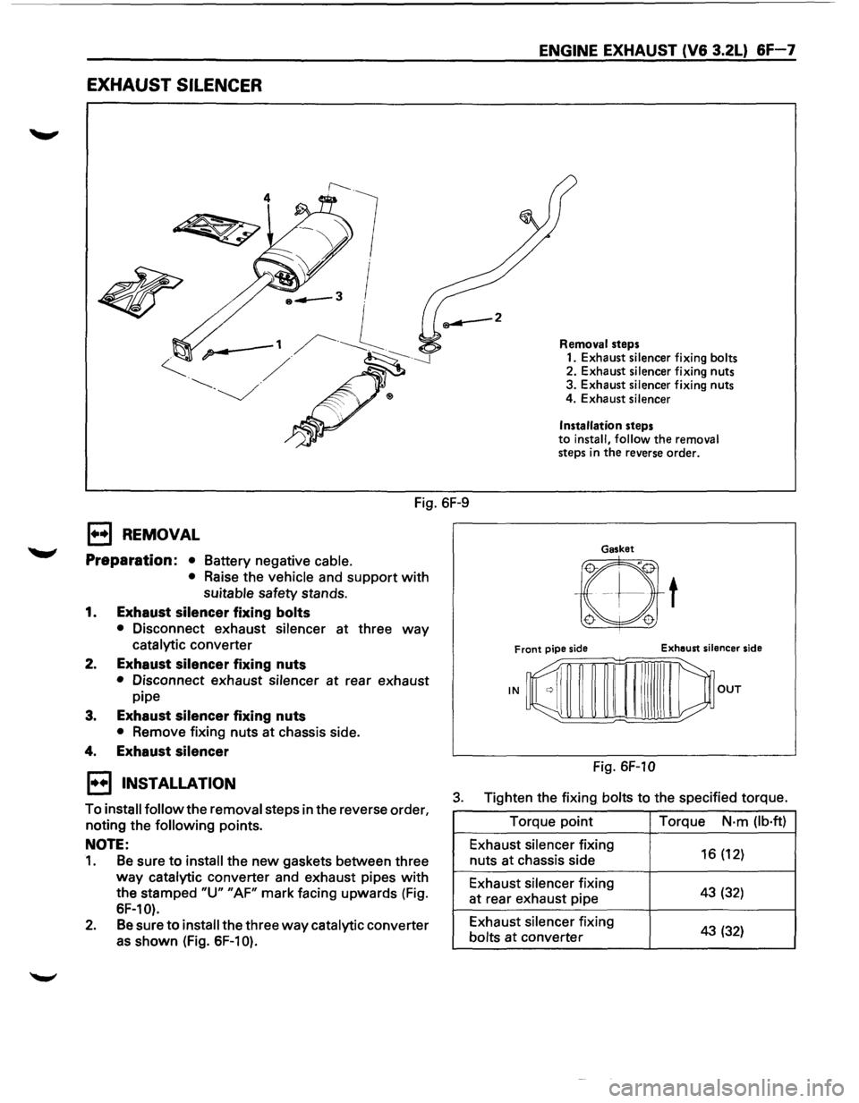
EXHAUST SILENCER
4
Fig. 6F-9
E) REMOVAL
Preparation: •
Battery negative cable.
• Raise the vehicle and support with
suitable safety stands.
1. Exhaust silencer fixing bolts
• Disconnect exhaust silencer at three way
catalytic converter
2. Exhaust silencer fixing nuts
• Disconnect exhaust silencer at rear exhaust
pipe
3. Exhaust silencer fixing nuts
• Remove fixing nuts at chassis side.
4. Exhaust silencer
ENGINE EXHAUST (V6 3.2L) 6F-7
Removal steps
1. Exhaust silencer fixing bolts 2. Exhaust silencer fixing nuts
3. Exhaust silencer fixing nuts
4. Exhaust silencer
Installation
steps to install, follow the removal steps in the reverse order.
Gasket
Fig. 6F-10
1••1 INSTALLATION
To install follow the removal steps in the reverse order,
noting the following points.
3. Tighten the fixing bolts to the specified torque.
NOTE:
1. Be sure to install the new gaskets between three
way catalytic converter and exhaust pipes with
the stamped "U" "AF" mark facing upwards (Fig.
SF-10).
2. Be sure to install the three way catalytic converter
as shown (Fig. SF-10).
Torque point
Exhaust silencer fixing
nuts at chassis side
Exhaust silencer fixing
at rear exhaust pipe
Exhaust silencer fixing
bolts
at converter Torque
N·m
(lb·ft)
16 (12)
43 (32)
43 (32)
Page 870 of 1928
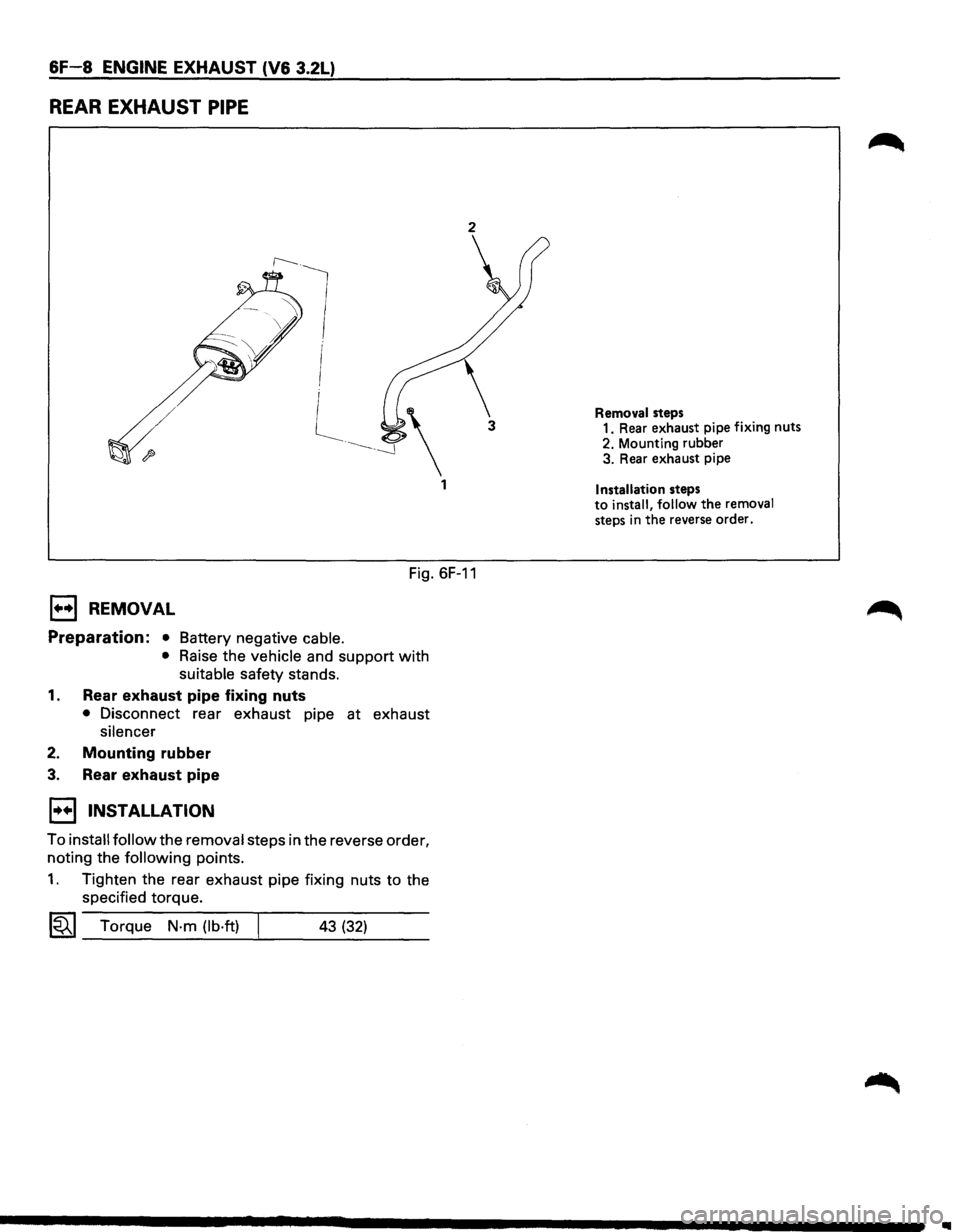
6F-8 ENGINE EXHAUST (V6 3.2L)
REAR EXHAUST PIPE
2
Fig. 6F-11
1+•1 REMOVAL
Preparation: • Battery negative cable.
• Raise the vehicle and support with
suitable safety stands.
1. Rear exhaust pipe fixing nuts
• Disconnect rear exhaust pipe at exhaust
silencer
2. Mounting rubber
3. Rear exhaust pipe
1••1 INSTALLATION
To install follow the removal steps in the reverse order,
noting the
following points.
1. Tighten the rear exhaust pipe fixing nuts to the
specified torque.
1«1 Torque N-m (lb·ft) 43 (32)
Removal steps 1. Rear exhaust pipe fixing nuts
2. Mounting rubber
3. Rear exhaust pipe
Installation steps to install, follow the removal steps in the reverse order.
1111