light ISUZU TROOPER 1995 Manual Online
[x] Cancel search | Manufacturer: ISUZU, Model Year: 1995, Model line: TROOPER, Model: ISUZU TROOPER 1995Pages: 1928
Page 508 of 1928
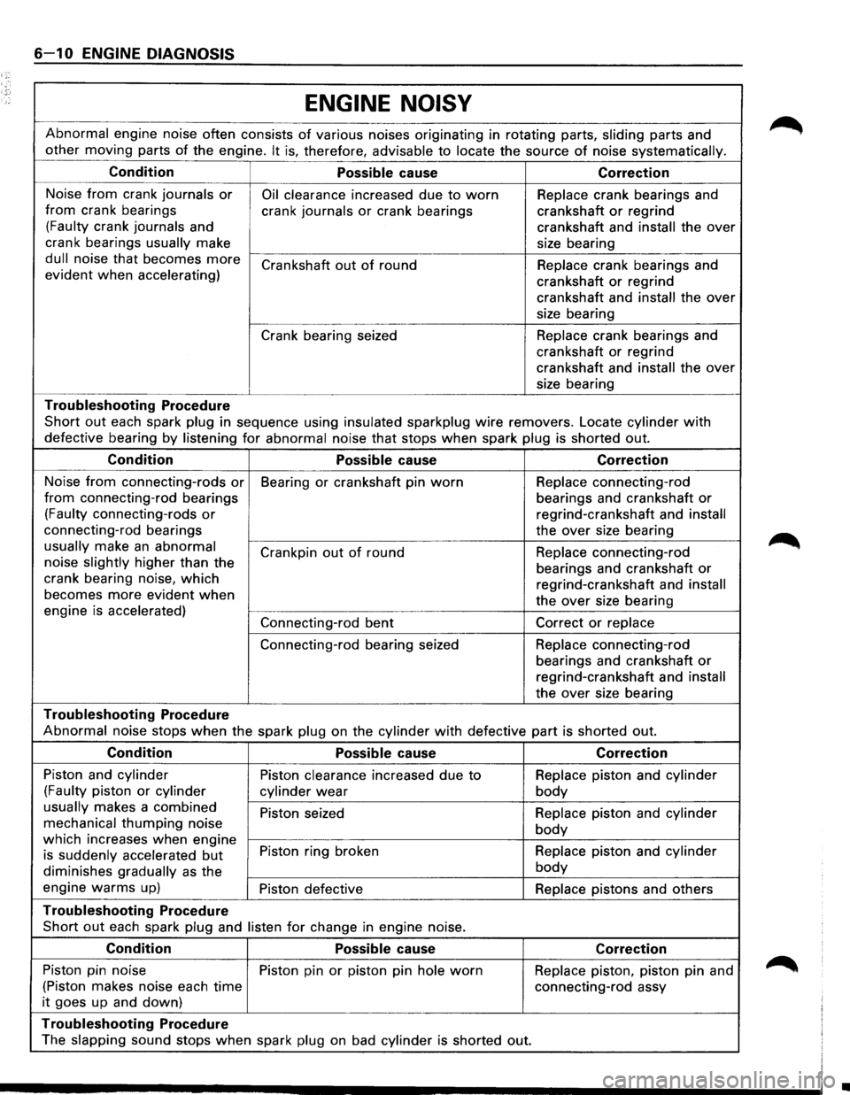
6-10 ENGINE DIAGNOSIS
ENGINE
NOISY
Abnormal engine noise often consists of various noises originating in rotating parts, sliding parts and
other moving parts
of the engine. It is, therefore, advisable to locate the source of noise systematically.
Condition
Possible cause Correction
Noise from crank journals or Oil clearance increased due to worn Replace crank bearings and
from crank bearings
crank journals
or crank bearings crankshaft or regrind
(Faulty crank journals and
crankshaft and
install the over
crank bearings
usually make
size bearing
dull noise that becomes more Crankshaft out of round
Replace crank bearings and
evident when accelerating)
crankshaft
or regrind
crankshaft and
install the over
size bearing
Crank bearing seized Replace crank bearings and
crankshaft or regrind
crankshaft and
install the over
size bearing
Troubleshooting Procedure
Short out each spark plug in sequence using insulated sparkplug wire removers. Locate cylinder with
defective bearing by listening for abnormal noise that stops when spark plug is shorted out.
Condition
Possible cause Correction
Noise from connecting-rods or Bearing or crankshaft pin worn Replace connecting-rod
from connecting-rod bearings
bearings and crankshaft or
(Faulty connecting-rods or regrind-crankshaft and install
connecting-rod bearings
the over size bearing
usually make an abnormal
Crankpin out of round Replace
connecting-rod
noise slightly higher than the
bearings and crankshaft
or crank bearing noise, which regrind-crankshaft and install becomes more evident when the over size bearing
engine is accelerated)
Connecting-rod bent
Correct or replace
Connecting-rod bearing seized Replace
connecting-rod
bearings and crankshaft
or
regrind-crankshaft and install
the over size bearing
Troubleshooting Procedure
Abnormal noise stops when the spark plug on the cylinder with defective part is shorted out.
Condition
Possible cause Correction
Piston and cylinder Piston clearance increased due to Replace piston and cylinder
(Faulty piston or cylinder
cylinder
wear body
usually makes a combined Piston seized Replace piston and cylinder
mechanical thumping noise body which increases when engine Piston ring broken Replace piston and cylinder
is suddenly accelerated but
diminishes gradually as the body
engine warms up) Piston defective Replace pistons and others
Troubleshooting Procedure
Short out each spark plug and listen for change in engine noise.
Condition
Possible cause Correction
Piston pin noise Piston pin or piston pin hole worn Replace piston, piston pin and
(Piston makes noise each time connecting-rod assy
it goes up and down)
Troubleshooting Procedure
The slapping sound stops when spark plug on bad cylinder is shorted out.
•
Page 525 of 1928
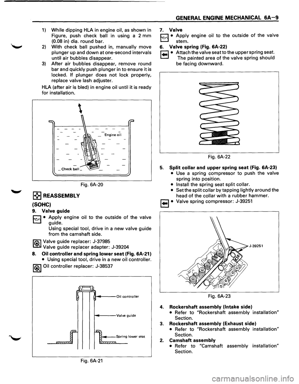
1) While dipping HLA in engine oil, as shown in
Figure, push check
ball in using a 2 mm
(0.08 in) dia. round bar.
2) With check ball pushed in, manually move
plunger up and down at one-second intervals
until
air bubbles disappear.
3) After air bubbles disappear, remove round
bar and
quickly push plunger in to ensure it is
locked. If plunger does not lock properly,
replace valve lash adjuster.
HLA (after air is
bled) in engine oil until it is ready
for installation.
-_ Engine oil
_Check ball_
Fig. 6A-20
l•!•l REASSEMBL V
(SOHC)
9. Valve guide
C1 • Apply engine oil to the outside of the valve
t..::::.l guide.
Using
special tool, drive in a new valve guide
from the camshaft side.
li5\l Valve guide replacer: J-37985
~ Valve guide replacer adapter: J-39204
8. Oil controller and spring lower seat (fig. 6A·21)
• Using special tool, drive in a new oil controller.
1®.1 Oil controller replacer: J-38537
~---Valve guide
Fig. 6A-21
GENERAL ENGINE MECHANICAL 6A-9
7. Valve
C1 • Apply engine oil to the outside of the valve
t..::::.l stem.
6. Valve spring (fig. 6A-22)
r=l • Attach the valve seatto the upper spring seat.
1.=.1 The painted area of the valve spring should
be facing downward.
Fig. 6A-22
5. Split collar and upper spring seat (Fig. 6A-23)
• Use a spring compressor to push the valve
spring into position.
• Install the spring seat split collar.
• Set
the split collar by tapping lightly around the
head
of the collar with a rubber hammer.
, ... ,. Valve spring compressor: J-39251
J·39251
Fig. 6A-23
4. Rockershaft assembly (Intake side)
• Refer to "Rockershaft assembly installation"
Section.
3. Rockershaft assembly (Exhaust side)
• Refer to "Rockershaft assembly installation"
Section.
2. Camshaft assembly
• Refer to "Camshaft assembly installation"
Section.
Page 526 of 1928
6A-1 0 GENERAL ENGINE MECHANICAL
1. Camshaft bracket fixing bolts
• Refer to "Camshaft assembly installation"
Section.
(DOHC)
10. Valve guide
D • Apply engine oil to the outside of the valve
l::::::J guide. Using special tool, drive in a new valve
guide from the camshaft side.
I'Qi1 Valve guide replacer: J-37985
~ Valve guide replacer adapter: J-39204
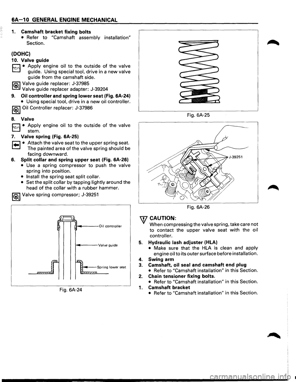
9. Oil controller and spring lower seat (Fig. 6A-24)
• Using special tool, drive in a new oil controller.
1®1 Oil Controller replacer: J-37986
8. Valve
D • Apply engine oil to the outside of the valve
l::::::J ste m .
7. Valve spring (Fig. 6A-25)
r:::l • Attach the valve seat to the upper spring seat.
1.=..1 The painted area of the valve spring should be
facing downward.
6. Split collar and spring upper seat (Fig. 6A-26)
• Use a spring compressor to push the valve
spring into position.
• Install the spring seat split collar.
• Set
the split collar by tapping lightly around the
head
of the collar with a rubber hammer.
I®J Valve spring compressor; J-39251
~---Valve guide
Fig. 6A-24 Fig.
6A-25
Fig. 6A-26
WCAUTION:
'V When compressing the valve spring, take care not
to contact the upper
valve seat with the oil
controller.
5. Hydraulic lash adjuster (HLA)
• Make sure that the HLA is clean and apply
engine oil to its outer surface before installation.
4. Swing arm
3. Camshaft, oil seal and camshaft end plug
• Refer to "Camshaft installation" in this Section.
2. Chain tensioner fixing bolts.
• Refer to "Camshaft installation" in this Section.
1. Camshaft bracket
• Refer to "Camshaft installation" in this Section.
•
Page 534 of 1928
6A-18 GENERAL ENGINE MECHANICAL
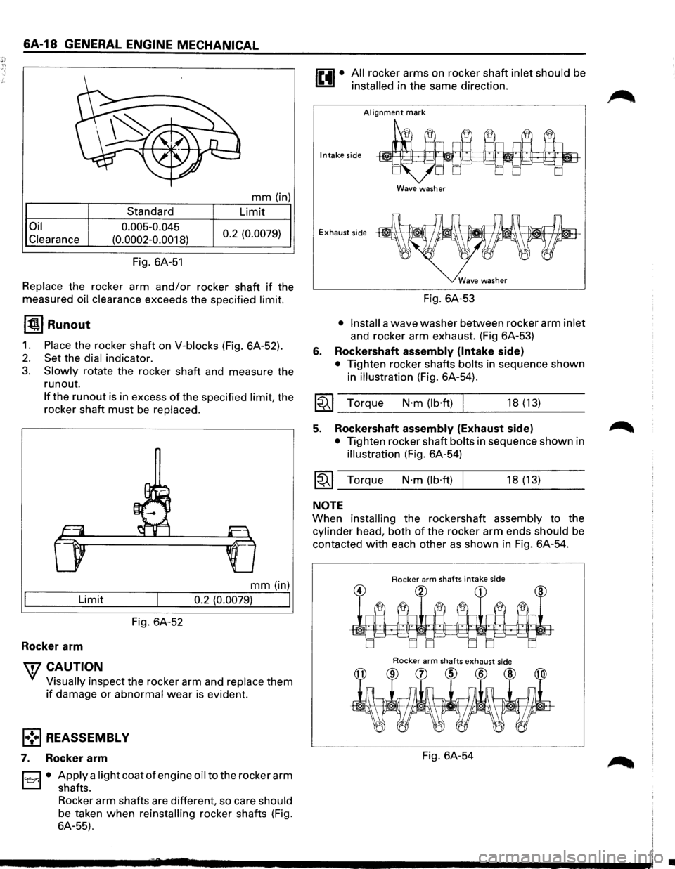
Oil
Clearance
Standard
0.005-0.045
(0.0002-0.0018)
Fig. 6A-51
mm (in)
Limit
0.2 (0.0079)
Replace the rocker arm and/or rocker shaft if the
measured
oil clearance exceeds the specified limit.
1~1 Runout
1. Place the rocker shaft on V-blocks (Fig. 6A-52).
2. Set the dial indicator.
3. Slowly rotate the rocker shaft and measure the
run out.
If the run out is in excess of the specified limit, the
rocker shaft
must be replaced.
mm (in)
Limit o.2 (o.oo79)
I
Fig. 6A-52
Rocker arm
wcAUTION
' Visually inspect the rocker arm and replace them
if damage or abnormal wear is evident.
l•!•l REASSEMBLY
7. Rocker arm
l'e::r.l • Apply a light coat of engine oil to the rocker arm
shafts.
Rocker arm shafts are different, so care
should
be taken when reinstalling rocker shafts (Fig.
6A-55).
All rocker arms on rocker shaft inlet should be
installed in the same direction.
AI ignment mark
Intake side
Wave washer
Exhaust side
6.
Fig. 6A-53
• Install a wave washer between rocker arm inlet
and rocker arm exhaust. (Fig 6A-53)
Rockershaft assembly (Intake side)
• Tighten rocker shafts bolts in sequence shown
in
illustration (Fig. 6A-54).
I~I __ To_r_q_ue ___ N_·_m_(_lb_·ft_)~l ______ 18_(_1_3) ____ _
5. Rockershaft assembly (Exhaust side) ~
• Tighten rocker shaft bolts in sequence shown in
illustration (Fig. 6A-54)
~~~ Torque N·m (lb·ft) I 18 (13)
NOTE
When installing the rockershaft assembly to the
cylinder head, both of the rocker arm ends should be
contacted
with each other as shown in Fig. 6A-54.
Rocker arm shafts intake side
Rocker arm shafts exhaust side
Fig. 6A-54
•
Page 578 of 1928
·,'
6A1-20 ENGINE (V6 3.2L DOHC AND SOHC)
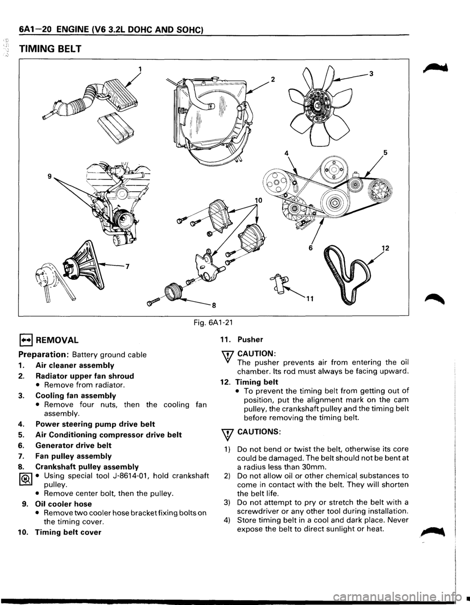
TIMING BELT
1 3
2
6 12
~ ..
Fig. 6A1-21
1••1 REMOVAL
Preparation: Battery ground cable
1. Air cleaner assembly
2. Radiator upper fan shroud
• Remove from radiator.
3. Cooling fan assembly
• Remove four nuts, then the cooling fan
assembly.
4. Power steering pump drive belt
5. Air Conditioning compressor drive belt
6. Generator drive belt
7. Fan pulley assembly
8. Crankshaft pulley assembly
~ • Using special tool J-8614-01, hold crankshaft
~ pulley.
•
Remove center bolt, then the pulley.
9. Oil cooler hose
• Remove two cooler hose bracket fixing bolts on
the timing cover.
10. Timing belt cover 11.
Pusher
'IT7 CAUTION:
'if The pusher prevents air from entering the oil
chamber. Its rod must always be facing upward.
12. Timing belt
• To prevent the timing belt from getting out of
position, put the alignment mark on the cam
pulley, the crankshaft pulley and the timing belt
before removing the timing belt.
w CAUTIONS:
1) Do not bend or twist the belt, otherwise its core
could be damaged. The belt should not be bent at
a radius
less than 30mm.
2) Do not allow oil or other chemica[ substances to
come in contact with the belt. They will shorten
the
belt life.
3) Do not attempt to pry or stretch the belt with a
screwdriver or any other tool during installation.
4) Store timing belt in a cool and dark place. Never
expose the
belt to direct sunlight or heat. ~
•
Page 580 of 1928
&A 1-22 ENGINE (V& 3.2L DOHC AND SOHC)
Fig. 6A1-27
Alignment mark on ~ timing belt ~
DOHC " ' on front plate
~~
Alignment mark
_","'
SOHC
DOHC
SOHC
/ Alignment mark on timing belt
Fig. 6A1-28
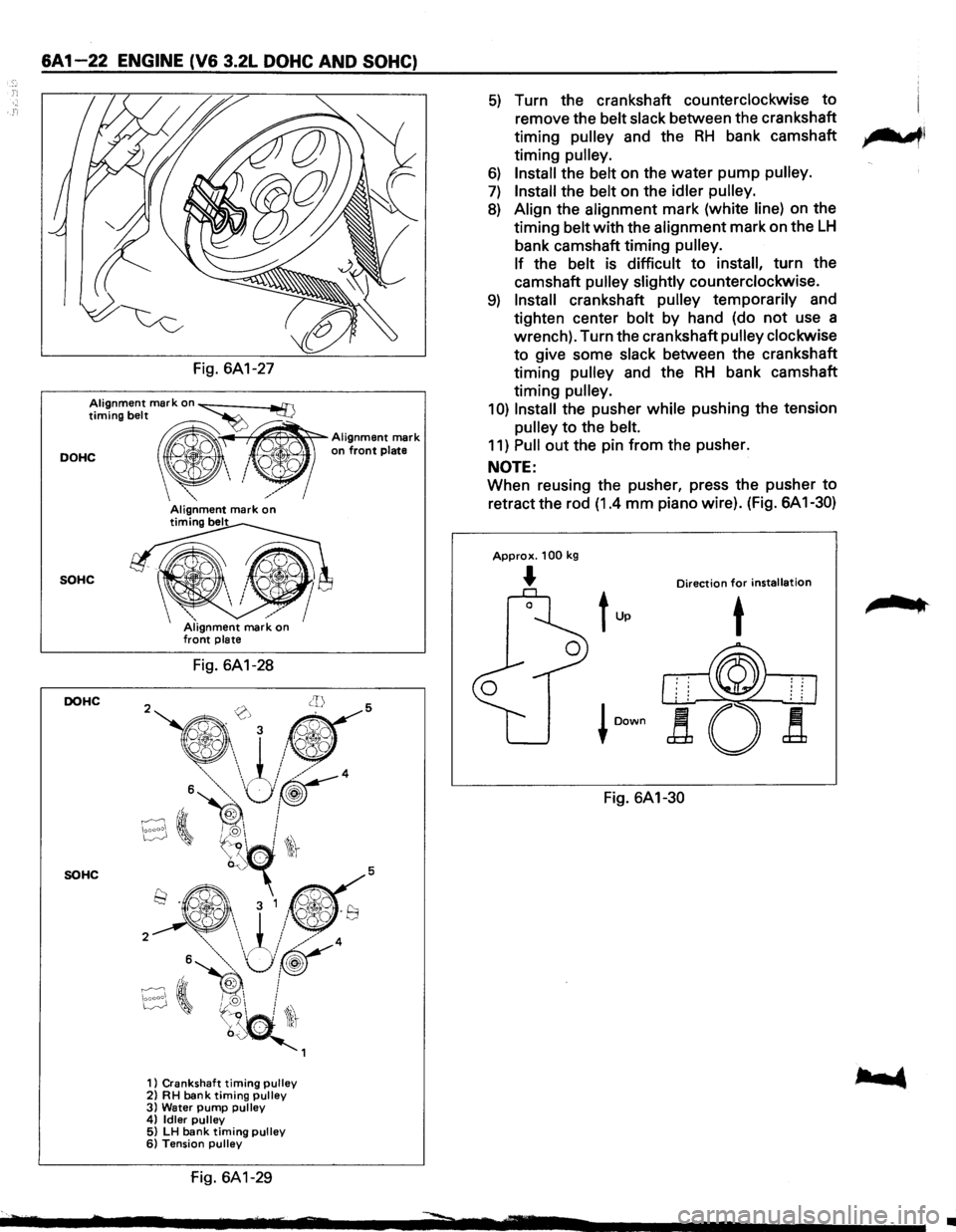
1) Crankshaft timing pulley 2) RH bank timing pulley 3) Water pump pulley 4) Idler pulley 5) LH bank timing pulley 6) Tension pulley
fig. 6A1-29
5) Turn the crankshaft counterclockwise to
remove the belt slack between the crankshaft
timing
pulley and the RH bank camshaft ,.......,,
timing pulley.
6) Install the belt on the water pump pulley.
7) Install the belt on the idler pulley.
8) Align the alignment mark (white line) on the
timing belt with the alignment mark on the
LH
bank camshaft timing pulley.
If
the belt is difficult to install, turn the
camshaft
pulley slightly counterclockwise.
9) Install crankshaft pulley temporarily and
tighten center bolt by hand (do
not use a
wrench). Turn the crankshaft
pulley clockwise
to give some slack between the crankshaft
timing
pulley and the RH bank camshaft
timing
pulley.
1 0) Install the pusher while pushing the tension
pulley to the belt.
11) Pull out the pin from the pusher.
NOTE:
When reusing the pusher, press the pusher to
retract the rod (1.4 mm piano wire). (Fig. 6A 1-30)
Approx. 100 kg
... Direction for installation
Fig. 6A1-30
,.. ..
•
Page 584 of 1928
6A1-26 ENGINE (V& 3.2L DOHC AND SOHC)
1••1 REMOVAL
Preparation: Battery ground cable
1. Air cleaner assembly
2. Radiator upper fan shroud
• Remove from radiator.
3. Cooling fan assembly
• Remove four nuts, then the cooling fan
assembly.
4. Accelerator Pedal cable
• Disconnect from throttle body and cable
bracket.
5. Vacuum booster hose
• Disconnect from common chamber.
6. Connectors
• Disconnect from Manifold Absolute Pressure,
canister Vacuum Switching Valve (VSV),
Exhaust
Gas Recirculation VSV, Intake Air
Temperature and ground cable.
7. High tension cables
• Disconnect from cylinder head cover.
8. Ignition Control Module assembly
• Disconnect three Electronic Ignition con
nectors.
• Remove three Electronic Ignition bracket fixing
bolts, and remove Electronic
Ignition assembly
with high tension cables.
9. Throttle body
• Remove four fixing bolts.
10. Vacuum hoses
• Disconnect vacuum hoses on canister VSV and
Exhaust Gas Recirculation
VSV from the
throttle body.
11. Positive Crankcase Ventilation hose
• Disconnect from common chamber.
12. Fuel Pressure Control Valve vacuum hose
• Disconnect from common chamber.
13. Evaporative Emission Canister Purge hose
• Disconnect from common chamber.
14. Exhaust Gas Recirculation Valve assembly
• Remove five bolts from common chamber,
exhaust manifold and cylinder head cover.
15. Common chamber
• Remove six bolts, two nuts and three bracket
fixing bolts, then remove the
common
chamber.
16. Fuelhoses
• Disconnect feed and return fuel hoses from fuel
pipes, and remove
two bracket fixing bolts on
the cylinder head cover.
17. Power steering pump drive belt
18. Air Conditioning compressor drive belt
19. Generator drive belt
20. Power steering pump
21. Fan pulley assembly
22. Crankshaft pulley assembly
lf5\l • Using special tool J-8614-01, hold crankshaft
t:::!il pulley.
•
Remove center bolt, then the pulley.
23. Oil cooler hose
• Remove two cooler hose bracket fixing bolts on
the timing belt cover.
24. Timing belt cover
25. Pusher
CAUTION:
The pusher prevents air from entering the oil chamber.
Its rod must always be facing upward.
26. Timing belt
CAUTIONS:
1) Do not bend or twist the belt, otherwise its core
could
be damaged. The belt should not be bent at
a radius less than 30mm.
2) Do not allow oil or other chemical substances to
come in contact with the belt. They will shorten
the belt life.
3) Do not attempt to pry or stretch the belt with a
screwdriver
or any other tool during installation.
4) Store timing belt in a cool and dark place. Never
expose the belt
to direct sunlight or heat.
27. Cylinder head cover
• Remove 11 fixing bolts, then the cylinder head
cover.
28. Camshaft
• Camshaft pulley fixing bolt and camshaft pulley
•
Front plate fixing bolts and front plate
• Camshaft bracket fixing bolts and camshaft
29. Rocker arm
• Fixing bolts and rocker arm
I••! INSTALLATION
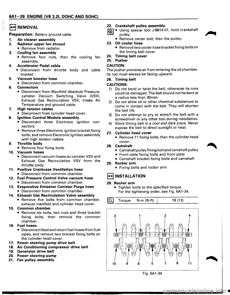
29. Rocker arm
• Tighten bolts to the specified torque.
For the tightening order, see Fig. 6A 1-34.
~~~ Torque N·m (lb·ft) 18 (13)
Fig. 6A1-34
•
Page 588 of 1928
6A1-30 ENGINE (V& 3.2L DOHC AND SOHC)
· ;~; E) REMOVAL
Preparation: Battery ground cable
1. Air cleaner assembly
2. Radiator upper fan shroud
• Remove from radiator.
3. Cooling fan assembly
• Remove four nuts, then the cooling fan
assembly.
4. Accelerator Pedal cable
• Disconnect from throttle body and cable
bracket.
5. Canister vacuum hose
• Disconnect from vacuum pipe.
6. Air vacuum hose
• Disconnect from common chamber.
7. Connectors
• Disconnect from Manifold Absolute, Canister
Vacuum Switching Valve
(VSV), Exhaust Gas
Recirculation
VSV, Intake Air Temperature and
ground cable.
8. High tension cables
• Disconnect from cylinder head cover.
9. Ignition Control Module assembly
• Disconnect three Electronic Ignition
connectors.
• Remove three Electronic Ignition bracket fixing
bolts, and remove Electronic
Ignition assembly
with high tension cables.
10. Throttle body
• Remove four fixing bolts.
11. Vacuum hoses
• Disconnect vacuum hoses on canisterVSVand
Exhaust
Gas Recirculation VSV from the
throttle body.
12. Positive Crankcase Ventilation hose
• Disconnect from common chamber.
13. Fuel Pressure Control Valve vacuum hose
• Disconnect from common chamber.
14. Evaporative Emission Canister Purge hose
• Disconnect from common chamber.
15. Exhaust Gas Recirculation Valve assembly
• Remove five bolts from common chamber,
exhaust manifold and cylinder head cover.
16. Common chamber duct
• Remove four bolts, four nuts and three bracket
fixing bolts, then remove the
common
chamber duct.
• Disconnect ground cable from rear side of
common chamber.
17. Common chamber
• Remove six bolts, two nuts and three bracket
fixing bolts, then remove the
common
chamber.
18. Fuel hoses
• Disconnect feed and return fuel hoses from fuel
pipes, and remove two bracket fixing bolts on
the cylinder head cover.
19. Power steering pump drive belt
20. Air Conditioning compressor drive belt
21. Generator drive belt
22. Power steering pump
23. Fan pulley assembly
24.
Crankshaft pulley assembly
1i0iJ • Using special tool J-8614-01, hold crankshaft
~ pulley.
•
Remove center bolt, then the pulley.
25. Oil cooler hose
• Remove two cooler hose bracket fixing bolts on
the timing belt cover.
26. Timing belt cover
27. Pusher
\fl CAUTION:
Yl The pusher prevents air from entering the oil
chamber.
Its rod must always be facing upward.
28. Timing belt
\fl CAUTIONS:
Yl 1) Do not bend or twist the belt, otherwise its
core could be damaged. The belt should
not
be bent at a radius less than 30mm.
2) Do not allow oil or other chemical substances
to come in contact
with the belt. They will
shorten the belt life.
3) Do not attempt to pry or stretch the belt with a
screwdriver
or any other tool during
installation.
4) Store timing belt in a cool and dark place.
Never expose the
belt to direct sunlight or
heat.
29. Cylinder head cover
• Remove 11 fixing bolts, then the cylinder head
cover.
30. Camshaft
• Camshaft pulley fixing bolt and camshaft pulley
•
Front plate fixing bolts and front plate
• Camshaft bracket fixing bolts and camshaft
31. Swing arm
• After removing the swing arm, attach a tag
showing the place
for swing arm.
32. Hydraulic lash adjuster (HLA)
• After removing the HLA, attach a tag showing
the place
for HLA.
\fl CAUTIONS:
Yl 1) Protect precision HLA from dust and foreign
materials.
2) Do not disassemble the HLA.
3) To clean the HLA, use a clean diesel oil.
•
Page 592 of 1928
6A1-34 ENGINE (V6 3.2L DOHC AND SOHC)
1••1 REMOVAL
Preparation:
Battery ground cable
1. Air cleaner assembly
2. Radiator upper fan shroud
• Remove from radiator.
3. Cooling fan assembly
• Remove four nuts, then the cooling fan
assembly.
4. Accelerator Pedal cable
• Disconnect from throttle body and cable
bracket.
5. Canister vacuum hose
• Disconnect from vacuum pipe.
6. Vacuum booster hose
• Disconnect from common chamber.
7. Connectors
• Disconnect from Manifold Absolute Pressure,
canister Vacuum Switching Valve (VSV),
Exhaust Gas Recirculation VSV, Intake Air
Temperature and ground cable.
8. High tension cables
• Disconnect from cylinder head cover.
9. Ignition Control Module assembly
• Disconnect three Electronic Ignition con
nectors.
• Remove three Electronic Ignition bracket fixing
bolts, and remove Electronic Ignition assembly
with high tension cables.
10. Throttle body
• Remove four fixing bolts.
11. Vacuum hoses
• Disconnect vacuum hoses on canister VSV and
Exhaust Gas Recirculation
VSV from the
throttle body.
12. Positive Crankcase Ventilation hose
• Disconnect from common chamber.
13. Fuel Pressure Control Valve vacuum hose
• Disconnect from common chamber.
14. Evaporative Emission Canister Purge hose
• Disconnect from common chamber.
15. Exhaust Gas Recirculation Valve assembly
• Remove five bolts from common chamber,
exhaust manifold and cylinder head cover.
16. Common chamber duct
• Remove four bolts, four nuts and three bracket
fixing
bolts, then remove the common
chamber duct.
• Disconnect ground cable from rear side of
common chamber.
17. Common chamber
• Remove six bolts, two nuts and three bracket
fixing
bolts, then remove the common
chamber.
18. Fuel hoses
• Disconnect feed and return fuel hoses from fuel
pipes, and remove two bracket fixing bolts on
the cylinder head cover.
19. Power steering pump drive belt
20.
Air Conditioning compressor drive belt
21. Generator drive belt
22. Power steering pump
23.
Fan pulley assembly
24. Crankshaft pulley assembly
liQil • Using special tool J-8614-01, hold crankshaft
~ pulley.
• Remove center bolt, then the pulley.
25. Oil cooler hose
• Remove two cooler hose bracket fixing bolts on
the
timing belt cover.
26. Timing belt cover
27. Pusher
\fl CAUTION:
'V The pusher prevents air from entering the oil
chamber. Its rod must always be facing upward.
28. Timing belt
\fl CAUTIONS:
'V 1) Do not bend or twist the belt, otherwise its
core could be damaged. The
belt should not
be bent at a radius less than 30mm.
2) Do not allow oil or other chemical substances
to come in contact with the belt. They will
shorten the belt life.
3) Do not attempt to pry or stretch the belt with a
screwdriver or any other tool during
installation.
4) Store timing belt in a cool and dark place.
Never expose the
belt to direct sunlight or
heat.
29. Cylinder head cover
• Remove 11 fixing bolts, then the cylinder head
cover.
30. Camshaft timing pulley
31. Front plate
32. Camshaft brackets
33. Chain tensioner fixing
bolts
34. Camshaft
• Remove the camshaft with chain and chain
tensioner.
35. Oil seal and camshaft end plug
II
Page 597 of 1928
E) REMOVAL
Preparation: Battery ground cable
1. Air cleaner assembly
2. Radiator upper fan shroud
• Remove from radiator.
3. Cooling fan assembly
• Remove four nuts, then the cooling fan
assembly.
4. Accelerator Padal cable
• Disconnect from throttle body and cable
bracket.
5. Canister vacuum hose
• Disconnect from vacuum pipe.
6. Vacuum booster hose
• Disconnect from common chamber.
7. Connectors
• Disconnect from Manifold Absolute Pressure,
canister Vacuum
Switching Valve (VSV),
Exhaust Gas Recirculation VSV, Intake Air
Temperature and ground cable.
8. High tension cables
• Disconnect from cylinder head cover.
9.
Ignition Control Module assembly
• Disconnect three Electronic Ignition con
nectors.
• Remove three Electronic Ignition bracket fixing
bolts, and remove Electronic Ignition assembly
with high tension cables.
10.
Throttle body
• Remove four fixing bolts.
11. Vacuum hoses
• Disconnect vacuum hoses on canister VSV and
Exhaust Gas Recirculation
VSV from the
throttle body.
12.
Positive Crankcase Ventilation hose
• Disconnect from common chamber.
13.
Fuel Pressure Control Valve vacuum hose
• Disconnect from common chamber.
14.
Evaporative Emission Canister Purge hose
• Disconnect from common chamber.
15.
Exhaust Gas Recirculation Valve assembly
• Remove five bolts from common chamber,
exhaust
manifold and cylinder head cover.
16.
Common chamber duct (DOHC)
• Remove four bolts, four nuts and three bracket
fixing
bolts, then remove the common
chamber duct.
• Disconnect ground cable from rear side of
common chamber.
ENGINE (V6 3.2L DOHC AND SOHC) 6A1-39
17. Common chamber
• Remove six bolts, two nuts and three bracket
fixing
bolts, then remove the common
chamber.
18.
Fuelhoses
• Disconnect feed and return fuel hoses from fuel
pipes, and remove two bracket fixing bolts on
the
cylinder head cover.
19.
Power steering pump drive belt
20. Air Conditioning compressor drive belt
21. Generator drive belt
22. Power steering pump
23. Fan pulley assembly
24. Crankshaft pulley assembly
~ • Using special tool J-8614-01, hold crankshaft
~ pulley.
•
Remove center bolt, then the pulley.
25. Oil cooler hose
• Remove two cooler hose bracket fixing bolts on
the timing
belt cover.
26.
Timing belt cover
27. Pusher
\fl CAUTION:
'if The pusher prevents air from entering the oil
chamber. Its rod must always be facing upward.
28.
Timing belt
CAUTIONS:
1) Do not bend or twist the belt, otherwise its
core
could be damaged. The belt should not
be bent at a radius less than 30mm.
2) Do not allow oil or other chemical substances
to come in contact
with the belt. They will
shorten the belt life.
3) Do not attempt to pry or stretch the belt with a
screwdriver
or any other tool during
installation.
4) Store timing belt in a cool and dark place.
Never expose the belt to direct sunlight or
heat.
29.
Cylinder head cover
30. Camshaft
• Camshaft pulley fixing bolt and camshaft pulley
•
Front plate fixing bolts and front plate
• Chain
tensioner fixing bolts (DOHC) and
camshaft bracket fixing
bolts
•
Camshaft, oil seal and camshaft end plug
31. Swing arm (DOHC)
32. Rocker
arm (SOHC)
•
Fixing bolt and rocker arm
33.
Spark plugs
• Keep valve in home position by feeding the
compressed air to the
cylinder from spark plug
hole.