light ISUZU TROOPER 1995 Manual PDF
[x] Cancel search | Manufacturer: ISUZU, Model Year: 1995, Model line: TROOPER, Model: ISUZU TROOPER 1995Pages: 1928
Page 457 of 1928
4-WHEEL ANTILOCK BRAKE SYSTEM (ASS) 5A4-47
DIAGNOSTIC TROUBLE CODES (DTCs)
When the warning light in the meter remains ON, the EBCM stores the fault identification and disables the
.........,.. ABS.
1. How to display and erase DTCs:
NOTE:
• If DTCs are not displayed, harness BB 14 may be disconnected. Repair the harness and try DTC
display again.
• DTCs can be displayed also by TECH 1. For further details, see "MODE F2: TROUBLE CODE" in this
section.
(1)
How to start DTC display:
• Confirm
that the vehicle has come to a complete stop (with the wheels standing still) and that the
brake pedal is not depressed. (Unless these two condition are satisfied, DTC display cannot be
started.)
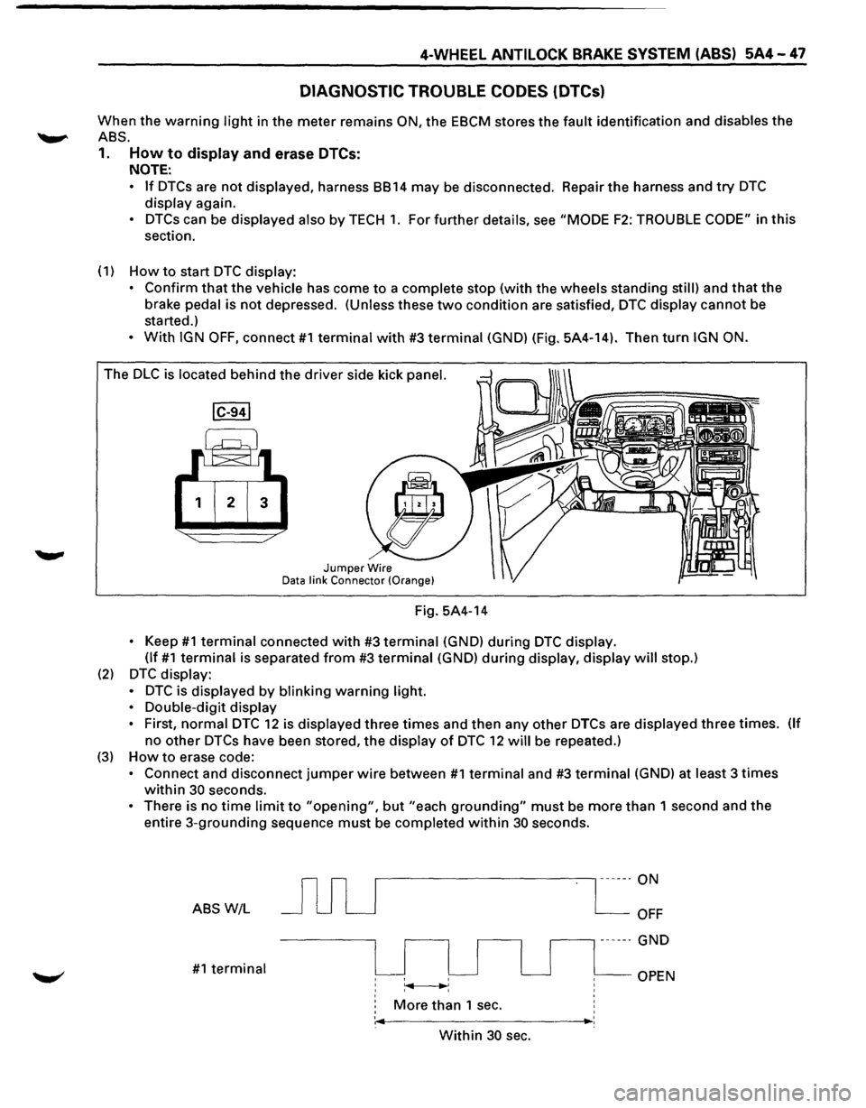
• With IGN OFF, connect #1 terminal with #3 terminal (GND) (Fig. 5A4-14). Then turn IGN ON.
The DLC is located behind the driver side kick panel.
1 2 3
Jumper Wire Data link Connector (Orange}
Fig. 5A4-14
• Keep #1 terminal connected with #3 terminal (GND) during DTC display.
(If
#1 terminal is separated from #3 terminal (GND) during display, display will stop.)
(2) DTC display:
•
DTC is displayed by blinking warning light.
•
Double-digit display
•
First, normal DTC 12 is displayed three times and then any other DTCs are displayed three times. (If
no other DTCs have been stored, the display of DTC 12 will be repeated.)
(3) How to erase code:
• Connect and disconnect jumper wire between #1 terminal and #3 terminal (GND) at least 3 times
within 30 seconds.
• There is no time limit to "opening", but "each grounding" must be more than 1 second and the
entire 3-grounding sequence must be completed within 30 seconds.
ABS W/L
#1 terminal
r---------------, ------ON
More than 1 sec.
OFF
.--------, ------ GND
OPEN
' ,._ _________ ,_:
Within 30 sec.
Page 459 of 1928
4-WHEEL ANTILOCK BRAKE SYSTEM (ABS) 5A4-49
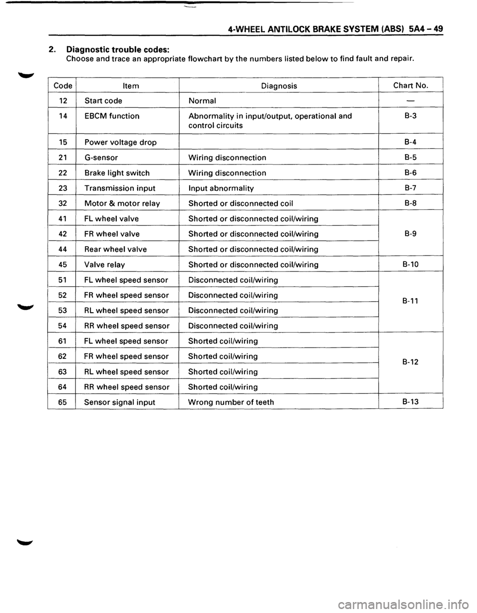
2. Diagnostic trouble codes:
Choose and trace an appropriate flowchart by the numbers listed below to find fault and repair.
Code
Item Diagnosis Chart
No.
12 Start code Normal -
14 EBCM function Abnormality in input/output, operational and B-3
control circuits
15 Power voltage drop B-4
21 G-sensor Wiring disconnection B-5
22 Brake light switch Wiring disconnection B-6
23 Transmission input Input abnormality B-7
32 Motor & motor relay
Shorted or disconnected coil B-8
41 FL wheel valve
Shorted or disconnected coil/wiring
42 FR wheel valve
Shorted or disconnected coil/wiring B-9
44 Rear wheel valve Shorted or disconnected coil/wiring
45 Valve relay Shorted or disconnected coil/wiring B-10
51 FL wheel speed sensor Disconnected coil/wiring
52 FR wheel speed sensor Disconnected coil/wiring B-11
53 RL wheel speed sensor Disconnected coil/wiring
54
RR wheel speed sensor Disconnected coil/wiring
61 FL wheel speed sensor Shorted coil/wiring
62 FR wheel speed sensor Shorted coil/wiring B-12
63 RL wheel speed sensor Shorted coil/wiring
64 RR wheel speed sensor Shorted coil/wiring
65 Sensor signal input Wrong number of teeth B-13
Page 460 of 1928
5A4-50 4-WHEEL ANTILOCK BRAKE SYSTEM (ABS)
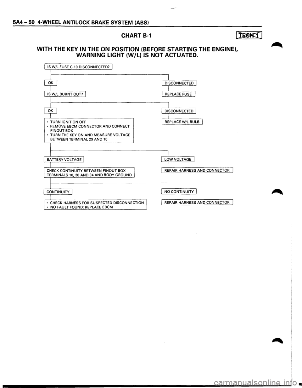
CHART B-1
WITH THE KEY IN THE ON POSITION (BEFORE STARTING THE ENGINE),
WARNING LIGHT
{W/L) IS NOT ACTUATED.
IS W/L FUSE C-10 DISCONNECTED? j
I
IS W/L BURNT OUT? I
I
• TURN IGNITION OFF
• REMOVE EBCM CONNECTOR AND CONNECT PINOUT BOX
• TURN THE KEY ON AND MEASURE VOLTAGE BETWEEN TERMINAL 29 AND 10
I
I
BATTERYVOLTAGE I
I
CHECK CONTINUITY BETWEEN PINOUT BOX I TERMINALS 10, 20 AND 34 AND BODY GROUND
l
I CONTINUITY I
I • CHECK HARNESS FOR SUSPECTED DISCONNECTION I • NO FAULT FOUND: REPLACE EBCM
I
I
DISCONNECTED I
I L REPLACE FUSE J
I L DISCONNECTED J
I I REPLACE W/L BULB I
I
I
LOWVOLTAGE I
I
I
REPAIR HARNESS AND CONNECTOR I
I
I
NO CONTINUITY I
I I REPAIR HARNESS AND CONNECTOR I
•
Page 461 of 1928
4-WHEEL ANTILOCK BRAKE SYSTEM (ABS) 5A4-51
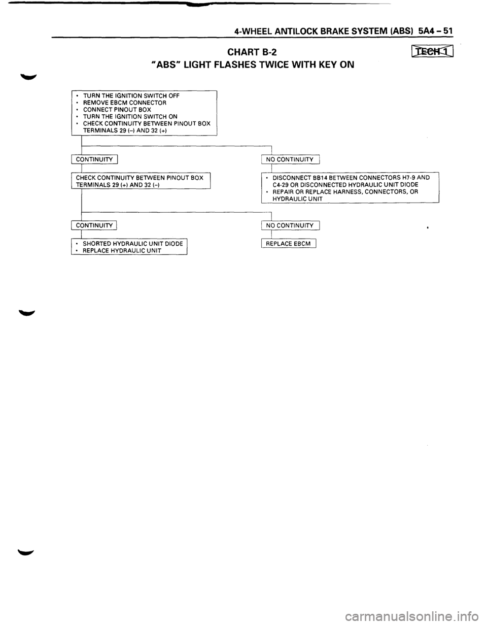
CHART B-2 [JECK¢(1
II ABS11 LIGHT FLASHES TWICE WITH KEY ON
• TURN THE IGNITION SWITCH OFF • REMOVE EBCM CONNECTOR
• CONNECT PINOUT BOX
• TURN THE IGNITION SWITCH ON CHECK CONTINUITY BETWEEN PINOUT BOX
TERMINALS 29 HAND 32 (+)
I CONTINUITY I NO CONTINUITY I
I CHECK CONTINUITY BETWEEN PINOUT BOX
I
DISCONNECT BB14 BETWEEN CONNECTORS H7-9 AND TERMINALS 29 (+)AND 32 H C4-29 OR DISCONNECTED
HYDRAULIC UNIT DIODE
• REPAIR OR REPLACE HARNESS, CONNECTORS, OR HYDRAULIC UNIT
I CONTINUITY I NO CONTINUITY I .
I • SHORTED HYDRAULIC UNIT DIODE I REPLACE EBCM I • REPLACE HYDRAULIC UNIT
Page 462 of 1928
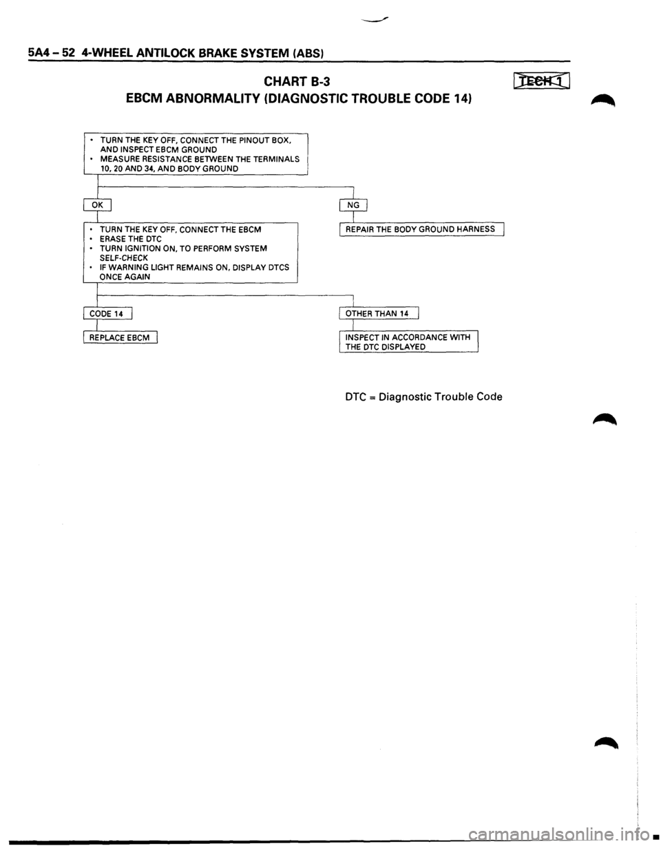
5A4-52 4-WHEEL ANTILOCK BRAKE SYSTEM (ABS)
CHART B-3 ~I
EBCM ABNORMALITY (DIAGNOSTIC TROUBLE CODE 14)
• TURN THE KEY OFF, CONNECT THE PINOUT BOX. AND INSPECT EBCM GROUND
• MEASURE RESISTANCE BETWEEN THE TERMINALS
10, 20 AND 34, AND BODY GROUND
T
~ $
• TURN THE KEY OFF, CONNECT THE EBCM
• ERASE THE DTC I REPAIR THE BODY GROUND HARNESS I
• TURN IGNITION ON, TO PERFORM SYSTEM
SELF-CHECK
IF WARNING LIGHT REMAINS ON, DISPLAY DTCS
ONCE AGAIN
I
r I CODE14 I I OTHER THAN
14 I
I I
REPLACE EBCM I !INSPECT IN ACCORDANCE WITH I THE DTC DISPLAYED
DTC = Diagnostic Trouble Code
•
Page 465 of 1928
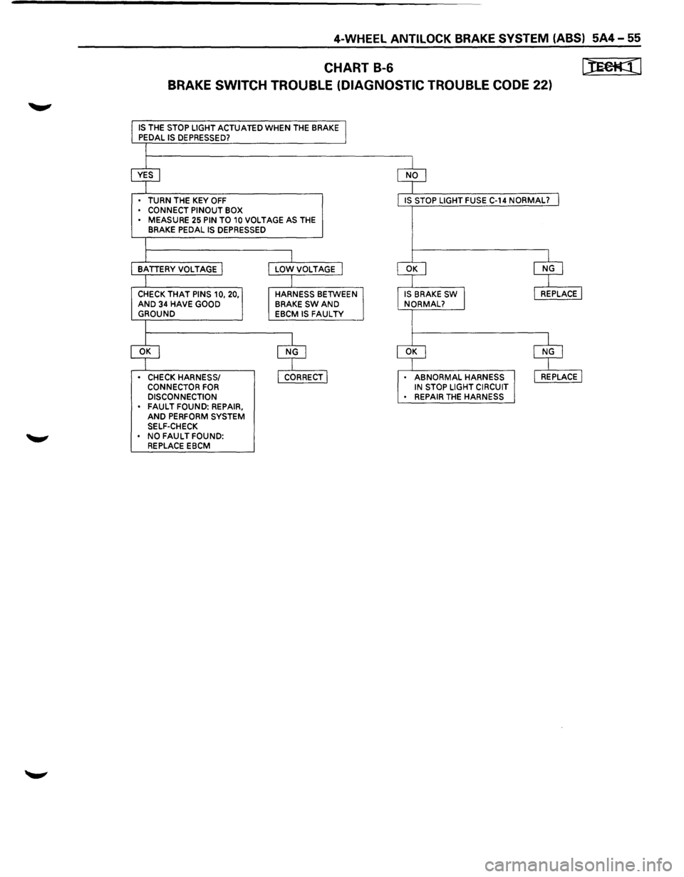
4-WHEEL ANTILOCK BRAKE SYSTEM (ABSI 5A4-55
CHART B-6
BRAKE
SWITCH TROUBLE (DIAGNOSTIC TROUBLE CODE 22)
IS THE STOP LIGHT ACTUATED WHEN THE BRAKE
PEDAL IS DEPRESSED?
TURN THE KEY OFF
CONNECT PINOUT BOX
MEASURE
25 PIN TO 10 VOLTAGE AS THE
BRAKE PEDAL IS DEPRESSED
CHECK THAT PINS 10, 20, AND 34 HAVE GOOD GROUND
• CHECK HARNESS/
CONNECTOR FOR DISCONNECTION
• FAULT FOUND: REPAIR, AND PERFORM SYSTEM SELF-CHECK • NO FAULT FOUND:
REPLACE EBCM
HARNESS BETWEEN
BRAKE SWAND EBCM IS FAUL TV
• ABNORMALHARNESS IN STOP LIGHT CIRCUIT
REPAIR THE HARNESS
Page 474 of 1928
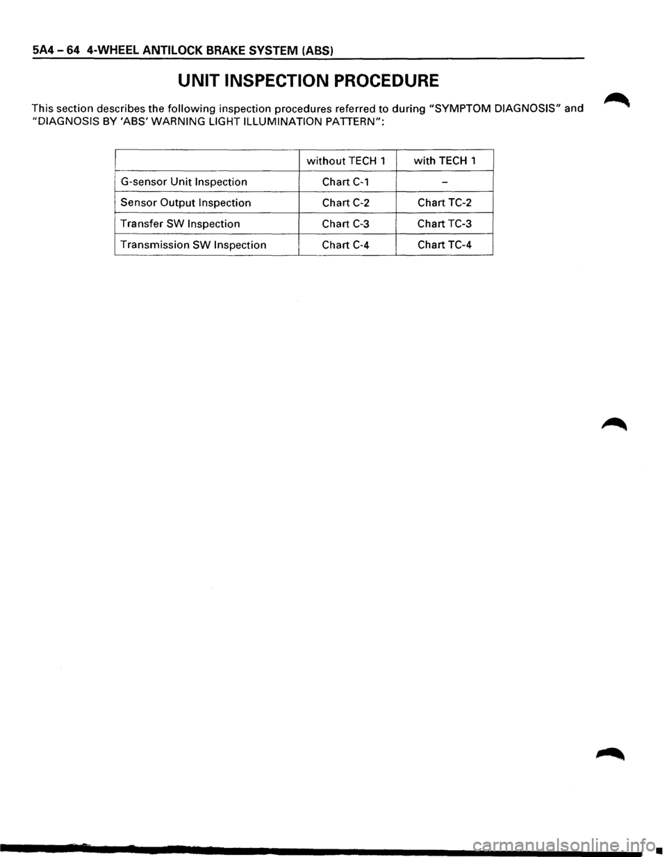
5A4 -64 4-WHEEL ANTILOCK BRAKE SYSTEM (ABS)
UNIT INSPECTION PROCEDURE
This section describes the following inspection procedures referred to during "SYMPTOM DIAGNOSIS" and
"DIAGNOSIS BY 'ABS' WARNING LIGHT ILLUMINATION PATTERN":
without TECH 1 with TECH 1
G-sensor
Unit Inspection Chart C-1 -
Sensor Output Inspection Chart C-2 Chart TC-2
Transfer
SW Inspection Chart C-3 Chart TC-3
Transmission
SW Inspection Chart C-4 Chart TC-4
•
Page 491 of 1928
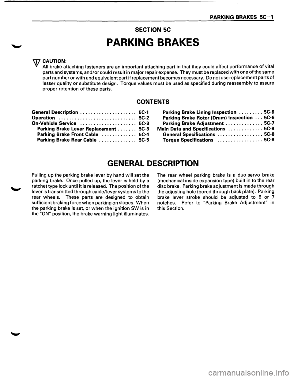
PARKING BRAKES 5C-1
SECTION 5C
PARKING BRAKES
'\f7 CAUTION:
Yf All brake attaching fasteners are an important attaching part in that they could affect performance of vital
parts and systems, and/or could result in major repair expense. They must be replaced with one ofthe same
part number
or with and equivalent part if replacement becomes necessary. Do not use replacement parts of
lesser quality or substitute design. Torque values must be used as specified during reassembly to assure
proper retention
of these parts.
CONTENTS
General Description ..................... 5C-1
Operation . . . . . . . . . . . . . . . . . . . . . . . . . . . . . 5C-2
On-Vehicle Service
..................... 5C-3
Parking Brake Lever Replacement . .
. . . . .
5C-3
Parking Brake Front Cable . .
. . . . . . . . . . .
5C-4
Parking Brake Rear Cable . .
. . . . . . . . . . . .
5C-5
Parking Brake Lining Inspection ......... 5C-6
Parking Brake Rotor (Drum) Inspection ... 5C-6
Parking Brake Adjustment .............. 5C-7
Main Data and Specifications ............. 5C-8
General
Specifications ................. 5C-8
Torque Specifications ................. 5C-8
GENERAL DESCRIPTION
Pulling up the parking brake lever by hand will set the
parking brake.
Once pulled up, the lever is held by a
ratchet type
lock until it is released. The position of the
lever is transmitted through cable/lever systems to the
rear
wheels. These parts are designed to obtain
sufficient braking force
when parking on slopes. When
the parking brake is set,
or when the ignition SW is in
the
"ON" position, the brake warning light illuminates.
The rear wheel parking brake is a duo-servo brake
(mechanical inside expansion type) built in to the rear
disc brake. Parking brake adjustment is made through
the adjusting
hole (bored through back plate). Parking
brake
lever stroke should be adjusted to 6 or 7
notches. Refer
to "Parking Brake Adjustment" in
this Section.
Page 497 of 1928
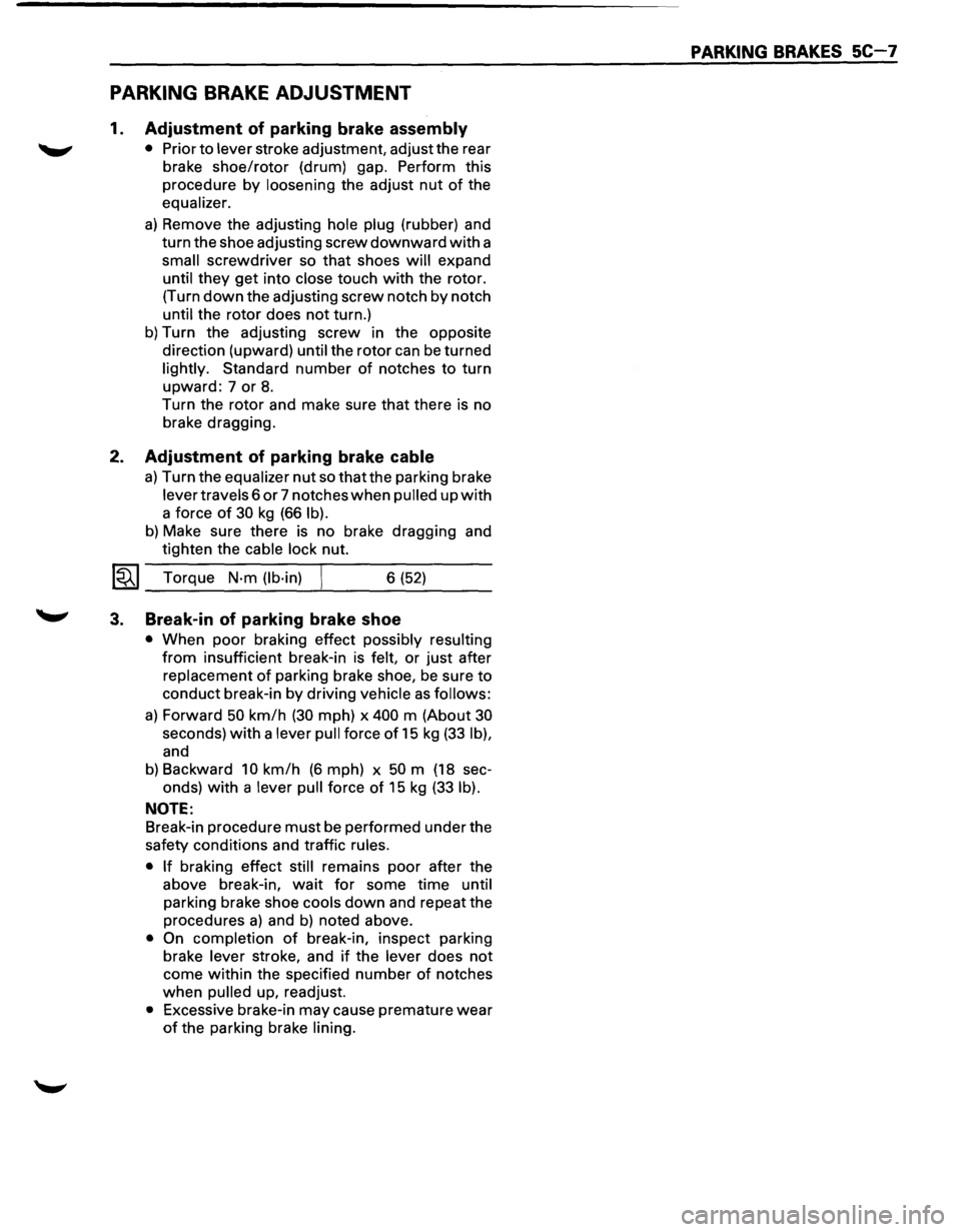
PARKING BRAKE ADJUSTMENT
1. Adjustment of parking brake assembly
• Prior to lever stroke adjustment, adjust the rear
brake
shoe/rotor (drum) gap. Perform this
procedure
by loosening the adjust nut of the
equalizer.
a) Remove the adjusting hole plug (rubber) and
turn the shoe adjusting screw
downward with a
small screwdriver so that shoes will expand
until
they get into close touch with the rotor.
(Turn
down the adjusting screw notch by notch
until the rotor does not turn.)
b) Turn the adjusting screw in the opposite
direction (upward) until the rotor can
be turned
lightly. Standard
number of notches to turn
upward: 7 or 8.
Turn the rotor and make sure that there is no
brake dragging.
2. Adjustment of parking brake cable
a) Turn the equalizer nut so that the parking brake
lever travels 6
or 7 notches when pulled up with
a force of 30 kg (66 lb).
b) Make sure there is no brake dragging and
tighten the cable lock nut.
l~l Torque N·m (lb·in) 6 (52)
3. Break-in of parking brake shoe
• When poor braking effect possibly resulting
from insufficient break-in is felt, or just after
replacement
of parking brake shoe, be sure to
conduct break-in by driving vehicle as follows:
a) Forward 50 km/h (30 mph) x 400 m (About 30
seconds) with a lever pull force of 15 kg (33 lb),
and
b) Backward 10 km/h (6 mph) x 50 m (18 sec-
onds)
with a lever pull force of 15 kg (33 lb).
NOTE:
Break-in procedure must be performed under the
safety conditions and traffic rules.
• If braking effect still remains poor after the
above break-in,
wait for some time until
parking brake shoe cools
down and repeat the
procedures
a) and b) noted above.
• On completion of break-in, inspect parking
brake lever stroke, and
if the lever does not
come within the specified number of notches
when pulled up, readjust.
• Excessive brake-in may cause premature wear
of the parking brake lining.
PARKING BRAKES SC-7
Page 501 of 1928
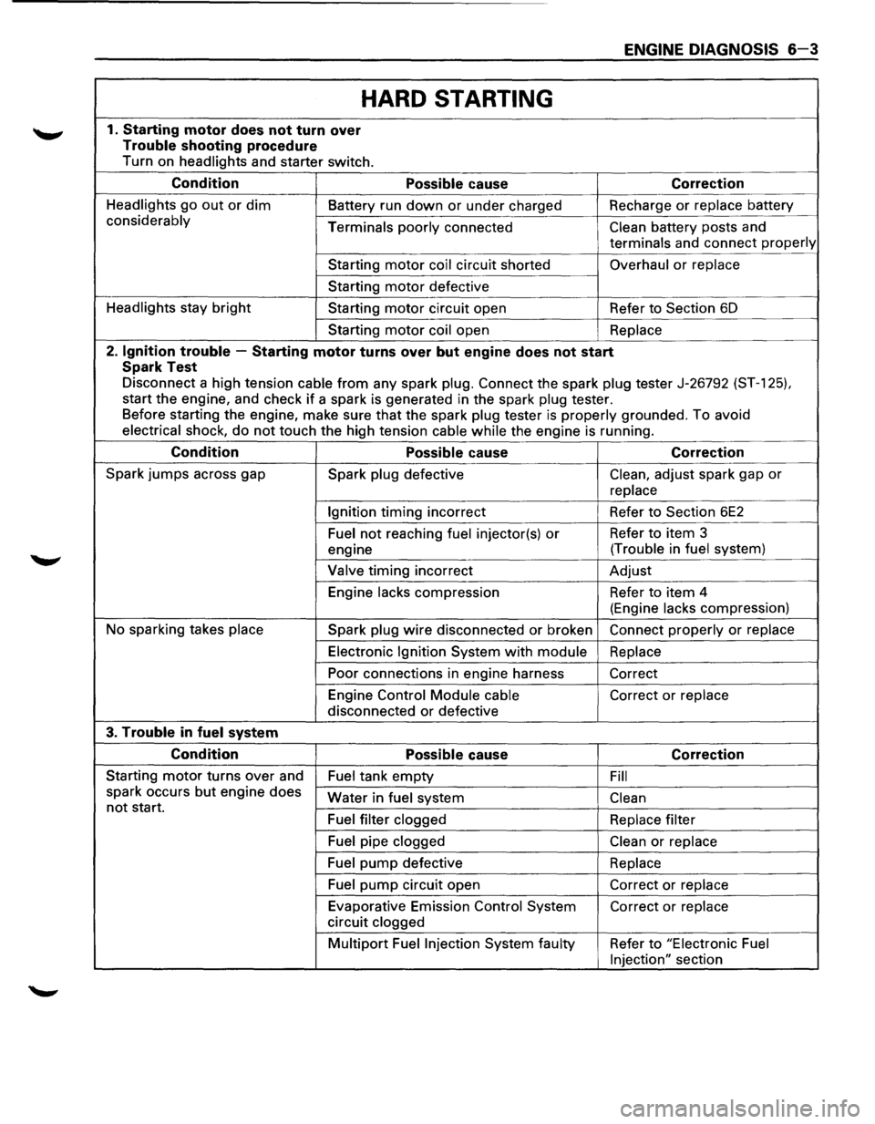
ENGINE DIAGNOSIS 6-3
HARD STARTING
1. Starting motor does not turn over
Trouble shooting procedure
Turn on headlights and starter switch.
Condition Possible cause Correction
Headlights go out or dim Battery run down or under charged Recharge or replace battery
considerably
Terminals poorly connected Clean battery posts and
terminals and connect properly
Starting motor coil circuit shorted Overhaul or replace
Starting motor defective
Headlights stay
bright Starting motor circuit open Refer to Section 6D
Starting
motor coil open Replace
2. Ignition trouble -Starting motor turns over but engine does not start
Spark Test
Disconnect a high tension cable from any spark plug. Connect the spark plug tester J-26792 (ST-1 25).
start the engine, and check if a spark is generated in the spark plug tester.
Before starting the engine, make sure
that the spark plug tester is properly grounded. To avoid
electrical shock, do not touch the high tension cable while the engine is running.
Condition Possible cause Correction
Spark jumps across gap
Spark plug defective Clean, adjust spark gap or
replace
Ignition
timing incorrect Refer to Section 6E2
Fuel not reaching fuel injector(s) or Refer to item 3
engine (Trouble
in
fuel system)
Valve
timing incorrect Adjust
Engine
lacks compression Refer to item 4
(Engine
lacks compression)
No sparking takes
place Spark plug wire disconnected or broken Connect properly or replace
Electronic Ignition System with module Replace
Poor connections in engine harness
Correct
Engine Control
Module cable Correct or replace
disconnected or defective
3. Trouble in fuel system
Condition Possible cause Correction
Starting motor turns over and
Fuel tank empty Fill
spark occurs but engine does
not start. Water in fuel system Clean
Fuel filter clogged Replace filter
Fuel pipe clogged Clean or replace
Fuel pump defective
Replace
Fuel
pump circuit open Correct or replace
Evaporative Emission Control System Correct or replace
circuit clogged
Multipart Fuel Injection System faulty Refer to "Electronic Fuel
Injection"
section