brake sensor ISUZU TROOPER 1995 Workshop Manual
[x] Cancel search | Manufacturer: ISUZU, Model Year: 1995, Model line: TROOPER, Model: ISUZU TROOPER 1995Pages: 1928
Page 14 of 1928
OA-10 GENERAL INFORMATION
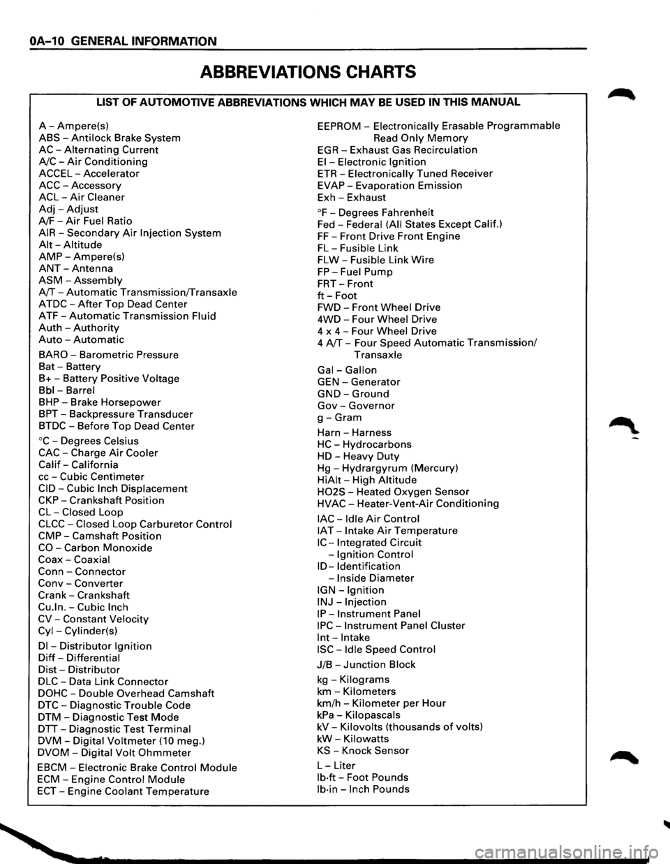
ABBREVIATIONS CHARTS
LIST OF AUTOMOTIVE ABBREVIATIONS WHICH MAY BE USED IN THIS MANUAL
A-Ampere(s)
ABS-Anti lock Brake System
AC-Alternating Current
A/C-Air Conditioning
ACCEL-Accelerator
ACC-Accessory
ACL-Air Cleaner
Adj-Adjust
A/F-Air Fuel Ratio
AIR-Secondary Air Injection System
Alt-Altitude
AMP-Ampere(s)
ANT-Antenna
ASM-Assembly
A/T-Automatic Transmission/Transaxle
ATDC-After Top Dead Center
ATF-Automatic Transmission Fluid
Auth -Authority
Auto -Automatic
BARO-Barometric Pressure
Bat -Battery
B+-Battery Positive Voltage
Bbl-Barrel
BHP-Brake Horsepower
BPT-Backpressure Transducer
BTDC-Before Top Dead Center
oc-Degrees Celsius
CAC-Charge Air Cooler
Calif-California
cc-Cubic Centimeter
CID-Cubic Inch Displacement
CKP-Crankshaft Position
CL-Closed Loop
CLCC-Closed Loop Carburetor Control
CMP-Camshaft Position
CO-Carbon Monoxide
Coax-Coaxial
Conn-Connector
Conv -Converter
Crank-Crankshaft
Cu.ln.-Cubic Inch
CV-Constant Velocity
Cyl-Cylinder(s)
Dl -Distributor Ignition
Diff-Differential
Dist-Distributor
DLC-Data Link Connector
DOHC-Double Overhead Camshaft
DTC-Diagnostic Trouble Code
DTM-Diagnostic Test Mode
DTT-Diagnostic Test Terminal
DVM-Digital Voltmeter (10 meg.)
DVOM-Digital Volt Ohmmeter
EBCM-Electronic Brake Control Module
ECM-Engine Control Module
ECT-Engine Coolant Temperature
EEPROM -Electronically Erasable Programmable
Read Only Memory
EGR-Exhaust Gas Recirculation
El-Electronic Ignition
ETR-Electronically Tuned Receiver
EVAP-Evaporation Emission
Exh-Exhaust
°F-Degrees Fahrenheit
Fed -
Federal (All States Except Calif.)
FF-Front Drive Front Engine
FL-Fusible Link
FLW-Fusible Link Wire
FP-Fuel Pump
FRT-Front
ft-Foot
FWD-Front Wheel Drive
4WD-Four Wheel Drive
4 x
4-Four Wheel Drive
4 A/T-Four Speed Automatic Transmission/
Transaxle
Gal-Gallon
GEN-Generator
GND-Ground
Gov-Governor
g-Gram
Harn -Harness
HC-Hydrocarbons
HD-Heavy Duty
Hg-Hydrargyrum (Mercury)
HiAit-High Altitude
H02S - Heated Oxygen Sensor
HVAC-Heater-Vent-Air Conditioning
lAC-Idle Air Control
IAT -Intake Air Temperature
IC-Integrated Circuit
-
Ignition Control
ID-Identification
-Inside Diameter
IGN-Ignition
INJ-Injection
IP-Instrument Panel
IPC-Instrument Panel Cluster
lnt-Intake
ISC-Idle Speed Control
J/B-Junction Block
kg -Kilograms
km-Kilometers
km/h -Kilometer per Hour
kPa-Kilopascals
kV-Kilovolts (thousands of volts)
kW-Kilowatts
KS -Knock Sensor
L-Liter
lb·ft-Foot Pounds
lb·in-Inch Pounds
Page 15 of 1928
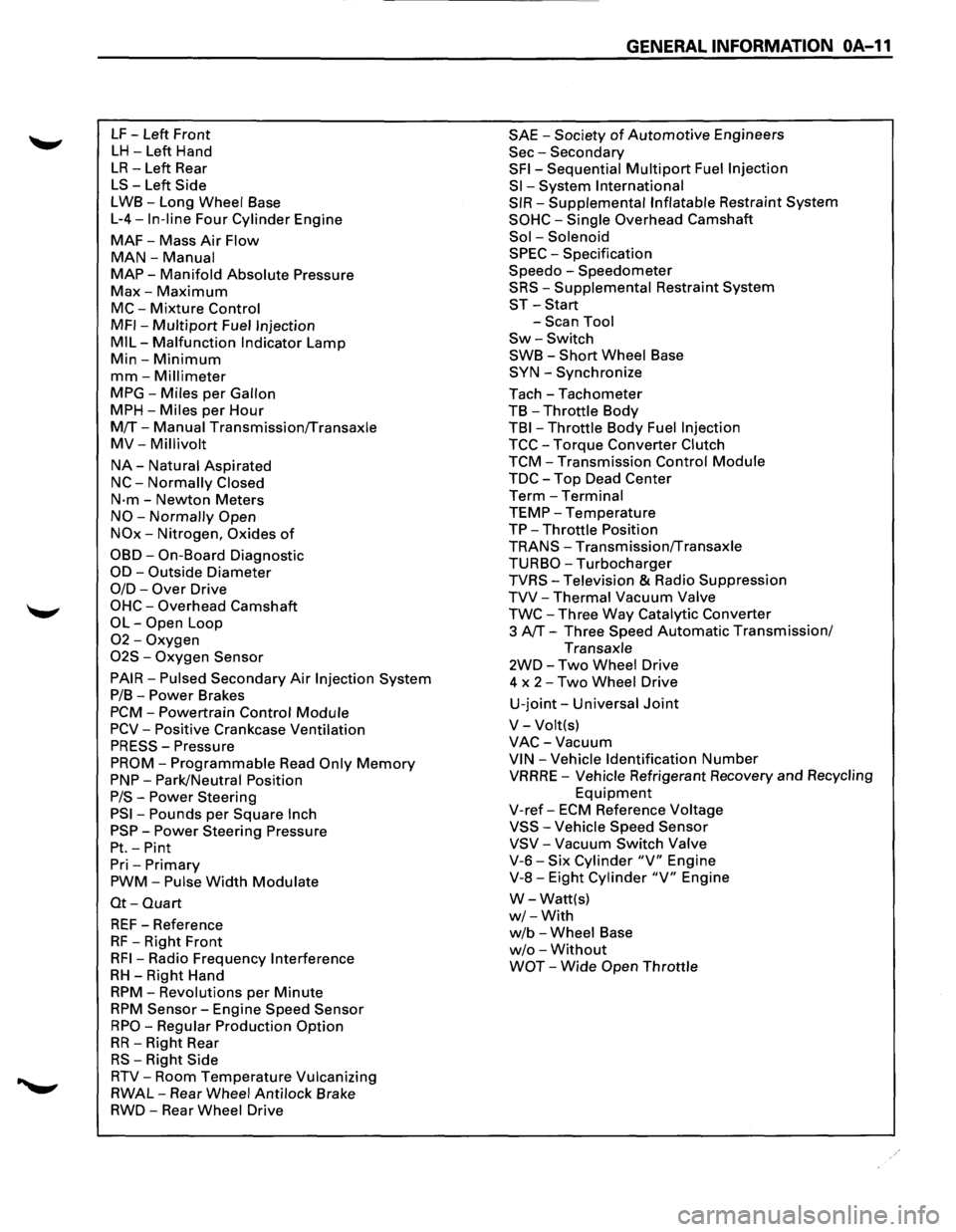
LF -Left Front
LH -Left Hand
LR-Left Rear
LS-Left Side
LWB-Long Wheel Base
L-4-In-line Four Cylinder Engine
MAF-Mass Air Flow
MAN-Manual
MAP-Manifold Absolute Pressure
Max-Maximum
MC-Mixture Control
MFI-Multipart Fuel Injection
MIL-Malfunction Indicator Lamp
Min-Minimum
mm-Millimeter
MPG-Miles per Gallon
MPH-Miles per Hour
M!f-Manual Transmission!fransaxle
MV-Millivolt
NA-Natural Aspirated
NC-Normally Closed
N·m-Newton Meters
NO-Normally Open
NOx-Nitrogen, Oxides of
OBD-On-Board Diagnostic
OD-Outside Diameter
0/D-Over Drive
OHC-Overhead Camshaft
OL-Open Loop
02-Oxygen
02S -Oxygen Sensor
PAIR-Pulsed Secondary Air Injection System
P/B-Power Brakes
PCM-Powertrain Control Module
PCV-Positive Crankcase Ventilation
PRESS-Pressure
PROM-Programmable Read Only Memory
PNP-Park/Neutral Position
P/S-Power Steering
PSI-Pounds per Square Inch
PSP-Power Steering Pressure
Pt.-Pint
Pri -Primary
PWM-Pulse Width Modulate
Ot-Quart
REF-Reference
RF -Right Front
RFI-Radio Frequency Interference
RH-Right Hand
RPM-Revolutions per Minute
RPM Sensor-Engine Speed Sensor
RPO-Regular Production Option
RR-Right Rear
RS-Right Side
RTV-Room Temperature Vulcanizing
RWAL-Rear Wheel Anti lock Brake
RWD-Rear Wheel Drive
GENERAL INFORMATION OA-11
SAE -Society of Automotive Engineers
Sec-Secondary
SFI-Sequential Multipart Fuel Injection
Sl-System International
SIR-Supplemental Inflatable Restraint System
SOHC-Single Overhead Camshaft
Sol -Solenoid
SPEC -Specification
Speedo -Speedometer
SRS-Supplemental Restraint System
ST-Start
-Scan Tool
Sw-Switch
SWB-Short Wheel Base
SYN-Synchronize
Tach-Tachometer
TB
-Throttle Body
TBI-Throttle Body Fuel Injection
TCC-Torque Converter Clutch
TCM-Transmission Control Module
TDC-Top Dead Center
Term-Terminal
TEMP-Temperature
TP-Throttle Position
TRANS-Transmission!fransaxle
TURBO-Turbocharger
TVRS-Television & Radio Suppression
TVV-Thermal Vacuum Valve
TWC-Three Way Catalytic Converter
3
AfT-Three Speed Automatic Transmission/
Transaxle
2WD-Two Wheel Drive
4 x
2-Two Wheel Drive
U-joint-Universal Joint
V-Volt(s)
VAC-Vacuum
VIN-Vehicle Identification Number
VRRRE -Vehicle Refrigerant Recovery and Recycling
Equipment
V-ref-ECM Reference Voltage
VSS-Vehicle Speed Sensor
VSV-Vacuum Switch Valve
V-6-Six Cylinder "V" Engine
V-8-Eight Cylinder "V" Engine
W-Watt(s)
w/-With
w/b -Wheel Base
w/o -Without
WOT-Wide Open Throttle
Page 171 of 1928
FRONT SUSPENSION 3C-7
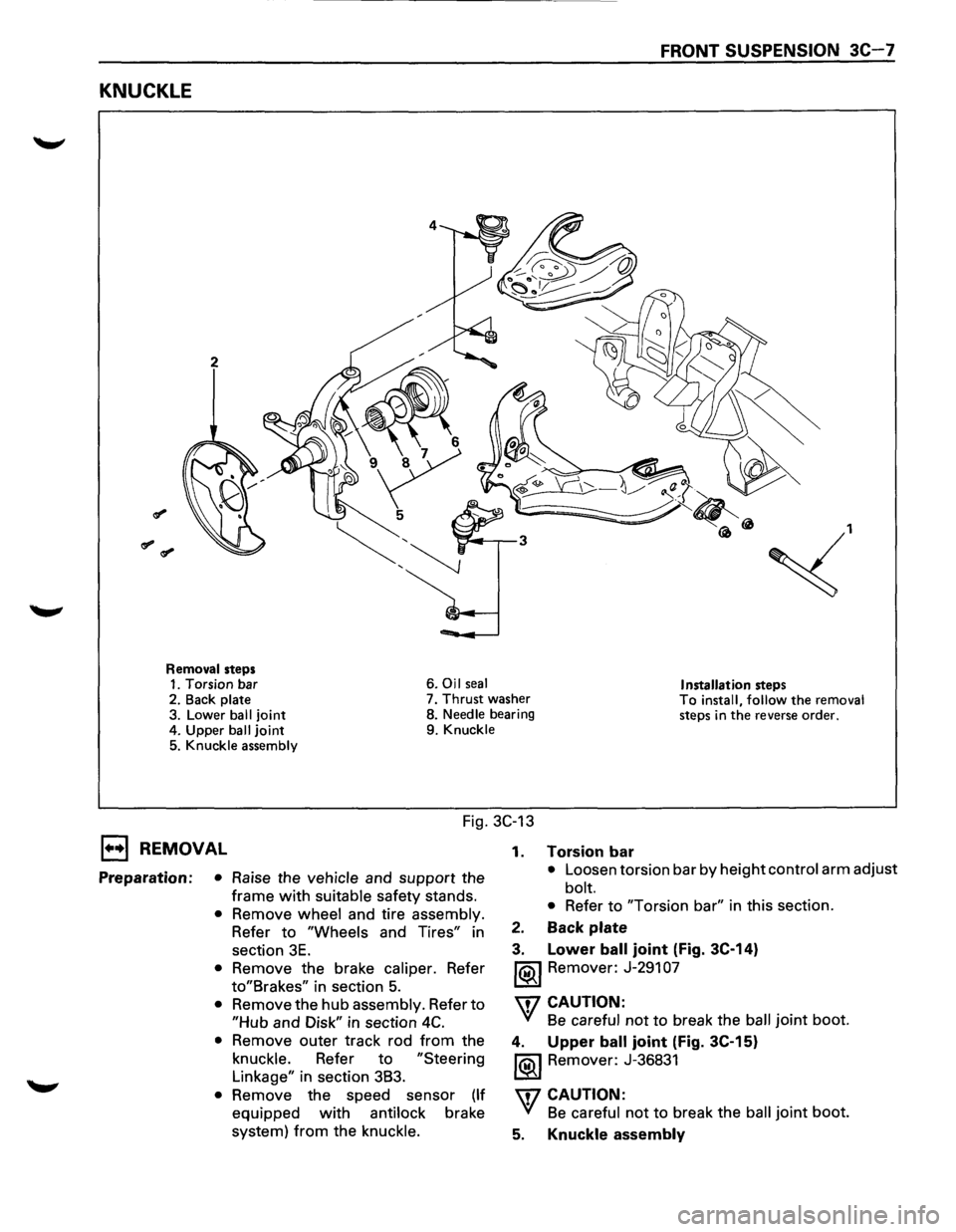
KNUCKLE
2
~,
Removal steps 1. Torsion bar 6. Oil seal Installation steps 2.
Back plate 7. Thrust washer To install, follow the removal steps in the reverse order. 3. Lower ball joint 8. Needle bearing
4. Upper
ball joint 9. Knuckle
5. Knuckle assembly
Fig. 3C-13
1••1 REMOVAL
Preparation: • Raise the vehicle and support the
frame
with suitable safety stands.
• Remove wheel and tire assembly.
Refer to
"Wheels and Tires" in
section
3E.
• Remove the brake caliper. Refer
to"Brakes" in section 5.
• Remove the hub assembly. Refer to
"Hub and Disk" in section 4C.
• Remove outer track rod from the
knuckle. Refer to
"Steering
Linkage" in section 3B3.
• Remove the speed sensor (If
equipped with antilock brake
system)
from the knuckle. 1.
Torsion bar
• Loosen
torsion bar by height control arm adjust
bolt.
• Refer to "Torsion bar" in this section.
2. Back plate
3. Lower ball joint (Fig. 3C-14)
1®.1 Remover: J-291 07
'\f7 CAUTION:
'(! Be careful not to break the ball joint boot.
4. Upper ball joint (Fig. 3C-15)
1®.1 Remover: J-36831
'\f7 CAUTION:
'(! Be careful not to break the ball joint boot.
5. Knuckle assembly
Page 174 of 1928
3C-1 0 FRONT SUSPENSION
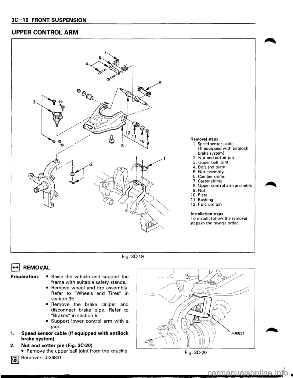
UPPER CONTROL ARM
3
V' , I
Fig. 3C-19
1••1 REMOVAL
Preparation: • Raise the vehicle and support the
frame
with suitable safety stands.
• Remove wheel and tire assembly.
Refer
to "Wheels and Tires" in
section
3E.
• Remove the brake caliper and
disconnect brake pipe. Refer
to
"Brakes" in section 5.
• Support lower control arm with a
jack.
1. Speed sensor cable (If equipped with antilock
brake system)
2.
Nut and cotter pin (Fig. 3C-20)
• Remove the upper ball joint from the knuckle.
1®.1 Remover: J-36831
Removal steps 1. Speed sensor cable
(If equipped with anti lock
brake system)
2. Nut and cotter pin 3. Upper ball joint 4. Bolt and plate 5. Nut assembly 6. Camber shims
7. Caster shims
8.
Upper control arm assembly
9. Nut 10. Plate 11. Bushing
12. Fulcrum pin
Installation steps To install, follow the removal steps in the reverse order.
Fig. 3C-20
Ill
Page 180 of 1928
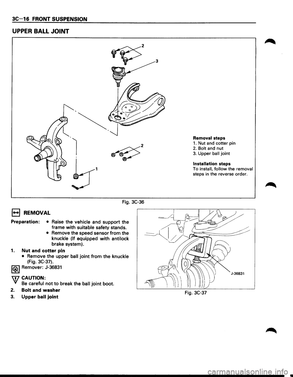
3C-16 FRONT SUSPENSION
UPPER BALL JOINT
1
Fig. 3C-36
E) REMOVAL
Preparation: • Raise the vehicle and support the
frame with
suitable safety stands.
• Remove the speed sensor from the
knuckle
(If equipped with antilock
brake system).
1. Nut and cotter pin
• Remove the upper ball joint from the knuckle
(Fig. 3C-37).
l®..l Remover: J-36831
\fl CAUTION:
VI Be careful not to break the ball joint boot.
2.
Bolt and washer
3. Upper ball joint
Removal steps
1. Nut and cotter pin
2. Bolt and nut
3. Upper ball joint
Installation steps
To install, follow the removal
steps in the reverse order.
Fig. 3C-37
Page 194 of 1928
30-8 REAR SUSPENSION
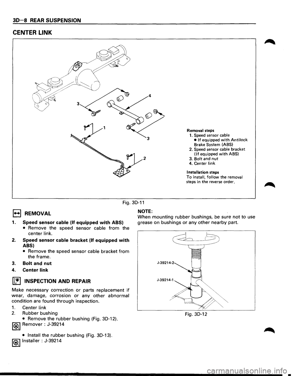
CENTER LINK
2
Removal steps
1. Speed sensor cable
• If equipped with Antilock Brake System (ABS)
2. Speed sensor
cable bracket (If equipped with ABS)
3.
Bolt and nut 4. Center link
Installation
steps
To
install, follow the removal steps in the reverse order.
1•+1 REMOVAL
Fig. 30-11
NOTE:
1.
2.
3.
Speed sensor cable (If equipped with ABS)
• Remove the speed sensor cable from the
center
link.
Speed sensor cable bracket (If equipped with
ABS)
• Remove the speed sensor cable bracket from
the frame.
Bolt and nut
4. Center link
~ INSPECTION AND REPAIR
Make necessary correction or parts replacement if
wear, damage, corrosion or any other abnormal
condition are found through inspection.
1. Center link
2. Rubber bushing
• Remove the rubber bushing (Fig. 30-12).
1®1 Remover : J-39214
• Install the rubber bushing (Fig. 30-13).
!®..I Installer : J-39214
When mounting rubber bushings, be sure not to use
grease on bushings
or any other nearby part.
J-39214-2
J-39214·1
Fig. 30-12
..
Page 244 of 1928
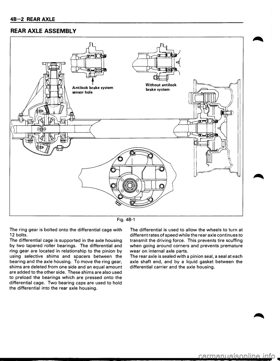
48-2 REAR AXLE
REAR AXLE ASSEMBL V
Antilock brake system
sensor
hole
Without antilock
brake system
Fig. 48-1
The ring gear
is bolted onto the differential cage with
12 bolts.
The differential cage is supported in the axle housing
by two tapered roller bearings. The differential and
ring gear are
located in relationship to the pinion by
using selective shims and spacers between the
bearing and the
axle housing. To move the ring gear,
shims are deleted from one side and an equal amount
are added to the other side. These shims are also used
to preload the bearings which are pressed onto the
differential cage. Two bearing caps are used to hold
the differential into the rear axle housing. The
differential is
used to allow the wheels to turn at
different rates
of speed while the rear axle continues to
transmit the driving force. This prevents tire scuffing
when going around corners and prevents premature
wear on internal axle parts.
The rear
axle is sealed with a pinion seal, a seal at each
axle shaft end, and by a liquid gasket between the
differential carrier and the axle housing.
II
Page 246 of 1928
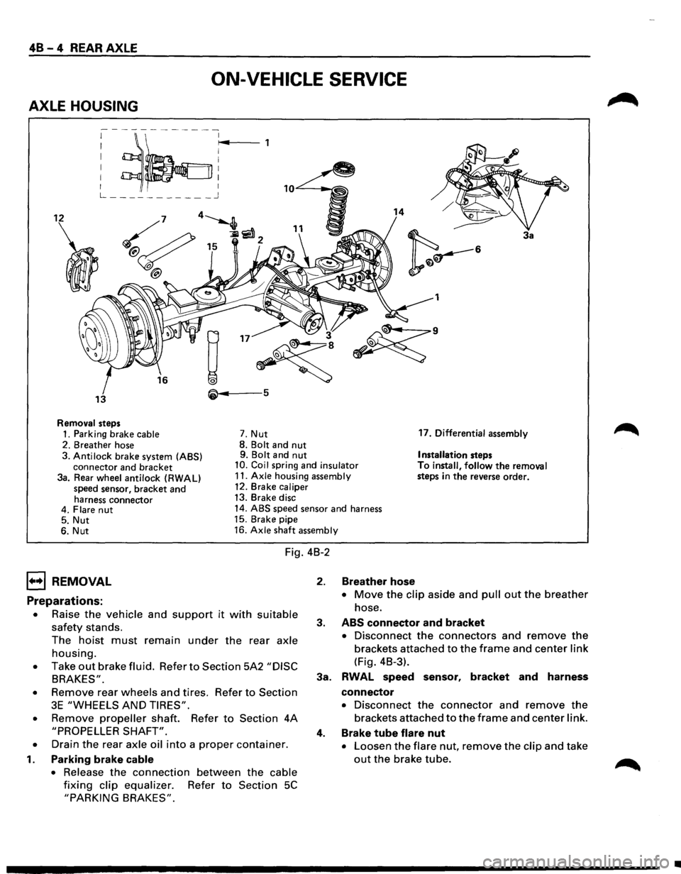
48-4 REAR AXLE
ON-VEHICLE SERVICE
AXLE HOUSING
; ~~:r~4 ,
L ___________ j
12 14
3a
1
• 3
~
~·
13 5
Removal steps
1. Parking brake cable 7. Nut 17.
Differential assembly
2. Breather hose 8.
Bolt and nut 9. Bolt and nut Installation steps
3. Anti lock brake system (ABS)
connector and bracket 10. Coil spring and insulator To install, follow the removal
steps in the reverse order.
3a. Rear wheel antilock (RWAL)
speed sensor, bracket and
harness connector 11.
Axle housing assembly
12. Brake caliper
13. Brake disc
4. Flare
nut 14. ABS speed sensor and harness
5. Nut 15.
Brake pipe
6. Nut 16.
Axle shaft assembly
Fig. 4B-2
1••1 REMOVAL
Preparations:
• Raise the vehicle and support it with suitable
safety stands.
The
hoist must remain under the rear axle
housing.
• Take out brake fluid. Refer to Section 5A2 "DISC
BRAKES".
•
Remove rear wheels and tires. Refer to Section
3E "WHEELS AND TIRES".
•
Remove propeller shaft. Refer to Section 4A
"PROPELLER SHAFT".
•
Drain the rear axle oil into a proper container.
1. Parking brake cable
•
Release the connection between the cable
fixing clip equalizer. Refer to Section 5C
"PARKING BRAKES".
2. Breather hose
• Move the clip aside and pull out the breather
hose.
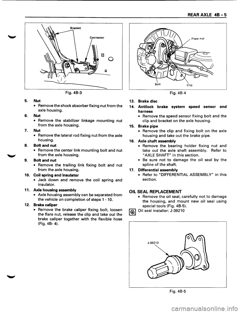
3. ABS connector and bracket
• Disconnect the connectors and remove the
brackets attached to the frame and center link
(Fig. 4B-3).
3a. RWAL speed sensor,
bracket and harness
connector
• Disconnect the connector and remove the
brackets attached to the frame and center link.
4. Brake tube flare nut
• Loosen the flare nut, remove the clip and take
out the brake tube.
•
Page 247 of 1928
5.
6.
7.
8.
........,
9.
10.
11.
12.
B 0
g
Fig. 48-3
Nut
• Remove the shock absorber fixing nut from the
axle housing.
Nut
• Remove the stabilizer linkage mounting nut
from the axle housing.
Nut
• Remove the lateral rod fixing nut from the axle
housing.
Bolt and nut
• Remove the center link mounting bolt and nut
from the axle housing .
Bolt and nut
• Remove the trailing link fixing bolt and nut
from the axle housing.
Coil spring and insulator
• Jack down and remove the coil spring and
insulator.
Axle housing assembly
• Axle
housing assembly can be separated from
the vehicle on completion of steps 1 -10.
Brake caliper
•
Remove the brake caliper fixing bolt, loosen
the
flare nut, release the clip and take out the
brake caliper
together with the flexible hose
(Fig. 48-
4).
REAR AXLE 48 - 5
Bolt Clip
Fig. 48-4
13. Brake disc
14.
Antilock brake system speed sensor and
harness
• Remove the speed sensor fixing bolt and the
clip and bracket on the axle housing.
15. Brake
pipe
• Remove the clip and fixing bolt on the axle
housing and take out the brake pipe.
16.
Axle shaft assembly
• Remove the bearing holder fixing nut and
take
out the axle shaft assembly. Refer to
"AXLE SHAFT" in this section.
• Be sure not to damage the oil seal by the
spline of the shaft.
17. Differential
assembly
• Refer to "DIFFERENTIAL ASSEMBLY" in this
section.
OIL SEAL REPLACEMENT
• Remove the oil seal, carefully not to damage
the housing, and mount new oil seal using
special tools (Fig. 48-5).
1®.1 Oil seal installer: J-39210
Fig. 48-5
Page 248 of 1928
48-6 REAR AXLE
1••1 INSTALLATION
17. Differential assembly
• Refer to "DIFFERENTIAL ASSEMBLY" in this
section.
16.
Axle shaft assembly
• Tighten the bearing holder mounting nut to the
specified torque.
~~~ Torque N·m (lb·ft) 74 (54)
• Be sure not to damage the oil seal by the spline
of the shaft.
15. Brake
pipe
14. Antilock brake system (ABS) speed sensor and
harness
• Refer to Section 5A4 "4-WHEEL ANTI-LOCK
BRAKE SYSTEM (ABS)".
13. Brake disc
12. Brake
caliper
• Refer to Section 5A2 "DISC BRAKES".
11.
Axle housing assembly
10. Coil spring and insulator
9. Bolt and nut
• For the procedures in Items 9-5, refer to Section
3D "REAR SUSPENSION".
8. Bolt and nut
7. Nut
6. Nut
5. Nut
4. Brake tube flare nut
• Refer to Section 5A2 "DISC BRAKES".
3a. Rear Wheel Antilock (RWAL) speed sensor,
bracket and harness connector
• Tighten the speed sensor bolt to the specified
torque.
1~1 Torque N-m (lb·ft) j 24 (18)
3. ABS connector and bracket
2. Breather hose
1. Parking brake cable
• Refer to Section 5C "PARKING BRAKES".