check engine light ISUZU TROOPER 1995 User Guide
[x] Cancel search | Manufacturer: ISUZU, Model Year: 1995, Model line: TROOPER, Model: ISUZU TROOPER 1995Pages: 1928
Page 377 of 1928
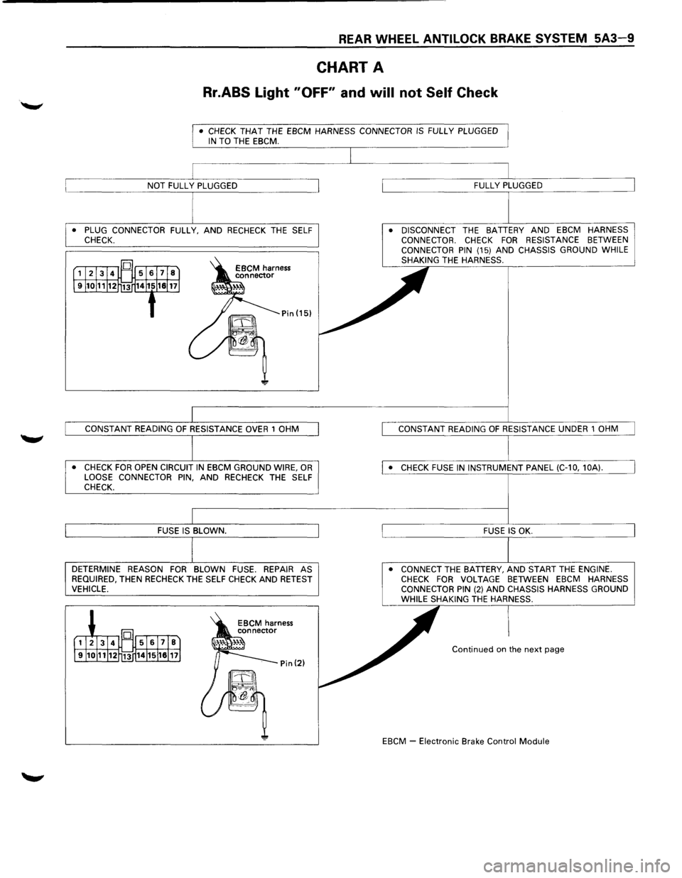
REAR WHEEL ANTILOCK BRAKE SYSTEM 5A3-9
CHART A
Rr.ABS Light "OFF" and will not Self Check
• CHECK THAT THE EBCM HARNESS CONNECTOR IS FULLY PLUGGED IN TO THE EBCM.
• PLUG CONNECTOR FULLY, AND RECHECK THE SELF
CHECK.
• CHECK FOR OPEN CIRCUIT IN EBCM GROUND WIRE, OR LOOSE CONNECTOR PIN, AND RECHECK THE SELF
CHECK.
DETERMINE REASON FOR BLOWN FUSE. REPAIR AS
REQUIRED, THEN RECHECK THE SELF CHECK AND RETEST VEHICLE. •
DISCONNECT
THE BATTERY AND EBCM HARNESS
CONNECTOR. CHECK FOR RESISTANCE BETWEEN
CONNECTOR PIN (15) AND CHASSIS GROUND WHILE
SHAKING THE HARNESS.
• CONNECT THE BATTERY, AND START THE ENGINE. CHECK FOR VOLTAGE BETWEEN EBCM HARNESS
CONNECTOR PIN (2) AND CHASSIS HARNESS GROUND WHILE SHAKING THE HARNESS.
Continued on the next page
EBCM
~ Electronic Brake Control Module
Page 379 of 1928
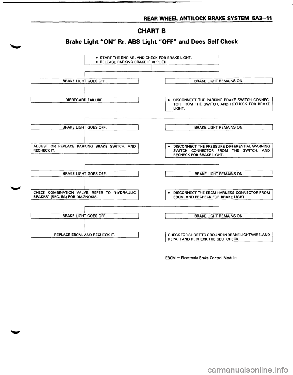
REAR WHEEL ANTILOCK BRAKE SYSTEM 5A3-11
CHART B
Brake Light 110N" Rr. ABS Light "OFF' and Does Self Check
• START THE ENGINE, AND CHECK FOR BRAKE LIGHT.
• RELEASE PARKING BRAKE IF APPLIED.
J
I
I BRAKE LIGHT GOES OFF. J BRAKE LIGHT REMAINS ON.
I
I DISREGARD FAILURE. J • DISCONNECT THE PARKING BRAKE SWITCH CONNEC-
TOR FROM THE SWITCH, AND RECHECK FOR BRAKE LIGHT.
I
I
I BRAKE LIGHT GOES OFF. I BRAKE LIGHT REMAINS ON.
I I ADJUST OR REPLACE PARKING BRAKE SWITCH, AND J • DISCONNECT THE PRESSURE DIFFERENTIAL WARNING RECHECK IT.
SWITCH CONNECTOR
FROM THE SWITCH, AND RECHECK FOR BRAKE LIGHT.
I
I
I BRAKE LIGHT GOES OFF. I BRAKE LIGHT REMAINS ON.
j
I CHECK COMBINATION VALVE. REFER TO "HYDRAULIC I • DISCONNECT THE EBCM HARNESS CONNECTOR FROM
BRAKES" (SEC. 5A) FOR DIAGNOSIS.
EBCM, AND RECHECK FOR BRAKE LIGHT.
I
I
I BRAKE LIGHT GOES OFF. I BRAKE LIGHT REMAINS ON.
I
I REPLACE EBCM, AND RECHECK IT. I CHECK FOR SHORT TO GROUND IN BRAKE LIGHTWIRE,AND
REPAIR AND RECHECK THE SELF CHECK.
EBCM
= Electronic Brake Control Module
Page 380 of 1928
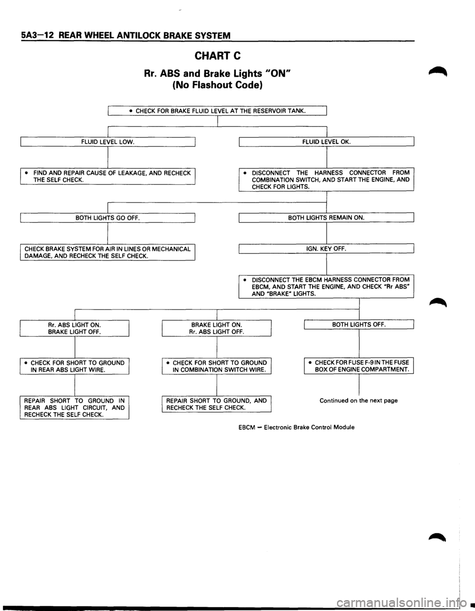
5A3~12 REAR WHEEL ANTILOCK BRAKE SYSTEM
CHART C
Rr. ABS and Brake Lights 110N"
(No Flashout Code}
I • CHECK FOR BRAKE FLUID LEVEL AT THE RESERVOIR TANK.
I
I FLUID LEVEL LOW. I FLUID LEVEL OK.
I
• FIND AND REPAIR CAUSE OF LEAKAGE, AND RECHECK I • DISCONNECT THE HARNESS CONNECTOR FROM THE
SELF CHECK. COMBINATION SWITCH, AND START THE ENGINE, AND CHECK FOR LIGHTS.
I BOTH LIGHTS GO OFF. I BOTH LIGHTS REMAIN ON.
I
CHECK BRAKE SYSTEM FOR AIR IN LINES OR MECHANICAL I IGN. KEY OFF. DAMAGE, AND RECHECK THE SELF CHECK.
• DISCONNECT THE EBCM HARNESS CONNECTOR FROM EBCM, AND START THE ENGINE, AND CHECK uRr ABS" AND UBRAKE" LIGHTS.
I Rr. ABS LIGHT ON.
I
BRAKE LIGHT ON.
I I BOTH LIGHTS OFF. BRAKE LIGHT OFF. Rr. ABS LIGHT OFF.
I • CHECK FOR SHORT TO GROUND I • CHECK FOR SHORT TO GROUND I I
• CHECK FOR FUSE F-91N THE FUSE IN REAR ABS LIGHT WIRE. IN COMBINATION SWITCH WIRE. BOX OF ENGINE COMPARTMENT.
I I REPAIR
SHORT TO GROUND IN I REPAIR SHORT TO GROUND, AND J Continued on the next page REAR ABS LIGHT CIRCUIT, AND RECHECK THE SELF
CHECK.
RECHECK THE SELF CHECK.
EBCM -
Electronic Brake Control Module
•
Page 384 of 1928
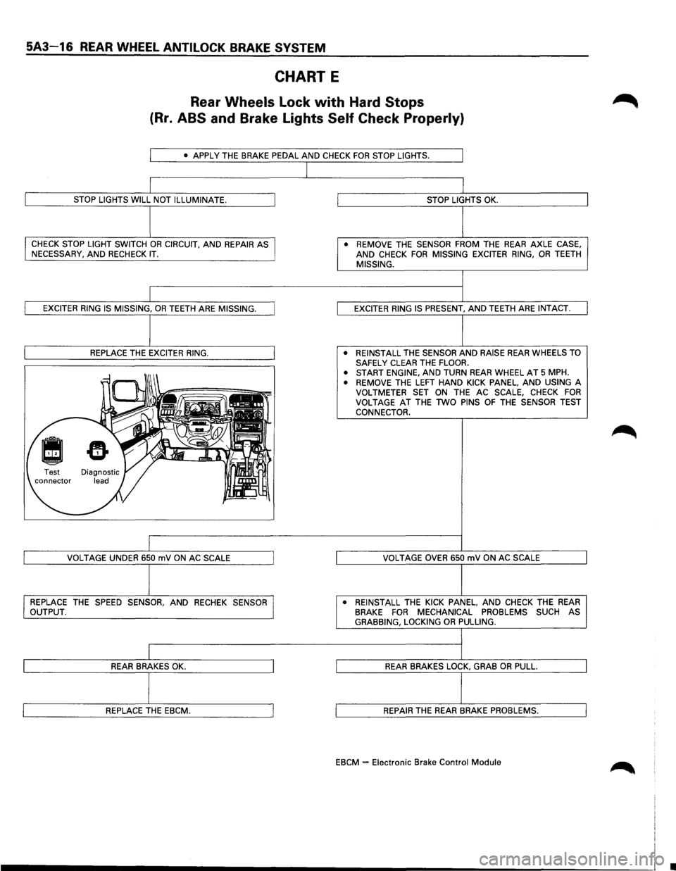
5A3-16 REAR WHEEL ANTILOCK BRAKE SYSTEM
CHART E
Rear Wheels Lock with Hard Stops
(Rr. ABS and Brake Lights Self Check Properly)
• APPLY THE BRAKE PEDAL AND CHECK FOR STOP LIGHTS.
STOP LIGHTS WILL NOT ILLUMINATE.
CHECK STOP LIGHT SWITCH OR CIRCUIT, AND REPAIR AS
NECESSARY, AND RECHECK IT.
EXCITER RING IS MISSING, OR TEETH ARE MISSING.
REPLACE
THE EXCITER RING.
VOLTAGE
UNDER 650 mV ON AC SCALE
REPLACE
THE SPEED SENSOR, AND RECHEK SENSOR
OUTPUT.
REAR BRAKES OK.
REPLACE THE EBCM.
STOP LIGHTS OK.
• REMOVE THE SENSOR FROM THE REAR AXLE CASE, AND CHECK FOR MISSING EXCITER RING, OR TEETH MISSING.
EXCITER
RING IS PRESENT, AND TEETH ARE INTACT.
• REINSTALL
THE SENSOR AND RAISE REAR WHEELS TO
SAFELY CLEAR THE FLOOR.
• START ENGINE, AND TURN REAR WHEEL AT 5 MPH.
• REMOVE THE LEFT HAND KICK PANEL, AND USING A
VOLTMETER SET ON THE AC SCALE, CHECK FOR VOLTAGE AT THE TWO PINS OF THE SENSOR TEST
CONNECTOR.
VOLTAGE
OVER 650 mV ON AC SCALE
• REINSTALL
THE KICK PANEL, AND CHECK THE REAR BRAKE FOR MECHANICAL PROBLEMS SUCH AS GRABBING, LOCKING OR PULLING.
REAR BRAKES LOCK, GRAB OR PULL.
REPAIR THE REAR BRAKE PROBLEMS.
EBCM = Electronic Brake Control Module
•
Page 411 of 1928
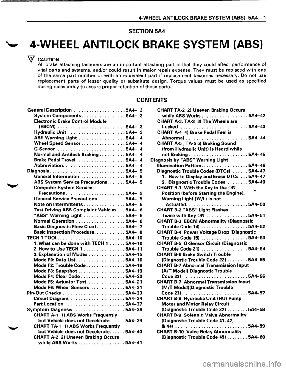
4-WHEEL ANTILOCK BRAKE SYSTEM (ABS) 5A4-1
SECTION 5A4
'--' 4-WHEEL ANTILOCK BRAKE SYSTEM (ABS)
CAUTION
All
brake attaching fasteners are an important attaching part in that they could affect performance of
vital parts and systems, and/or could result in major repair expense. They must be replaced with one
of the same part number or with an equivalent part if replacement becomes necessary. Do not use
replacement parts
of lesser quality or substitute design. Torque values must be used as specified
during reassembly to assure proper retention of these parts.
CONTENTS
General Description .................... 5A4-3
System Components ................. 5A4-3
Electronic Brake
Control Module ·
(EBCM) .......................... 5A4-3
Hydraulic Unit ...................... 5A4-3
ABS Warning Light .................. 5A4-4
Wheel
Speed Sensor ................. 5A4-4
G-Sensor
........................... 5A4-4
Normal and Antilock Braking .......... 5A4-4
Brake Pedal Travel
................... 5A4-4
Abbreviation ........................ 5A4-4
Diagnosis
............................. 5A4-5
General
Information ................. 5A4-5
ABS
System Service Precautions ....... 5A4-5
Computer System Service
Precautions
....................... 5A4-5
General Service Precautions
........... 5A4-5
Note on lntermittents ................ 5A4-6
Test Driving ABS Complaint Vehicles ... 5A4-6
II ABS11 Warning Light ................ 5A4-6
Normal Operation ................... 5A4-6
Basic
Diagnostic Flow Chart ........... 5A4-7
Basic
Inspection Procedure ............ 5A4-8
TECH 1
TOOL. ......................... 5A4-10
1. What can be done with TECH 1 ...... 5A4-10
2. How to Use TECH 1 ................ 5A4-11
3. Explanation of Modes .............. 5A4-15
Mode FO: Data List ................... 5A4-16
Mode F2: Trouble Code ............... 5A4-18
Mode F3: Snapshot .................. 5A4-19
Mode F4: Clear Code ................. 5A4-20
Mode F5: Actuator Test ............... 5A4-21
Mode F6: Wheel Sensors ............. 5A4-31
Pin-Out Checks ........................ 5A4-33
Circuit Diagram ..................... 5A4-34
Part Location ....................... 5A4-37
Symptom Diagnosis .................... 5A4-38
CHART A-1 1) ABS Works Frequently
but Vehicle does not Decelerate ...... 5A4-39
CHART TA-1 1) ABS Works Frequently
but Vehicle does not Decelerate ...... 5A4-40
CHART A-2 2) Uneven Braking Occurs
while ABS Works .................. 5A4-41
CHART TA-2 2) Uneven Braking Occurs
while ABS Works .................. 5A4-42
CHART A-3, T A-3 3) The Wheels are
Locked
........................... 5A4-43
CHART A-4 4) Brake Pedal Feel is
Abnormal ........................ 5A4-44
CHART A-5 , T A-5 5) Braking Sound
(from Hydraulic Unit) is Heard while
not Braking ....................... 5A4-45
Diagnosis by 11 ABS11 Warning Light
Illumination Pattern .................. 5A4-46
Diagnostic Trouble Codes (DTCs) ....... 5A4-47
1. How to Display and Erase DTCs ... 5A4-47
2. Diagnostic Trouble Codes ........ 5A4-49
CHART B-1 With the Key in the ON
Position (before Starting the Engine),
Warning Light (W /L) is not
•
Actuated ........................ 5A4-50
CHART B-2 II ABSII Light Flashes
Twice with Key ON ................ 5A4-51
CHART B-3 EBCM Abnormality (Diagnostic
Trouble Code 14) .................. 5A4-52
CHART B-4 Power Voltage Drop (Diagnostic
Trouble Code 15) .................. 5A4-53
CHART B-5 G-Sensor Circuit (Diagnostic
Trouble Code 21) .................. 5A4-54
CHART B-6 Brake Switch Trouble
(Diagnostic Trouble Code 22) ........ 5A4-55
CHART B-7 Abnormal Transmission Input
(A/T Modei)(Diagnostic Trouble
Code 23) ......................... 5A4-56
CHART B-7 Abnormal Transmission Input
(M/T Modei)(Diagnostic Trouble
Code 23) ......................... 5A4-57
CHART B-8 Hydraulic Unit (HU) Pump
Motor and Motor Relay Circuit
(Diagnostic Trouble Code 32) ........ 5A4-58
CHART B-9 Solenoid Valve Abnormality
(Diagnostic Trouble Code 41, 42,
& 44) ............................ 5A4-59
CHART B-10 Valve Relay Abnormality
(Diagnostic Trouble Code 45) ........ 5A4-60
Page 413 of 1928
4-WHEEL ANTILOCK BRAKE SYSTEM (ABS) 5A4-3
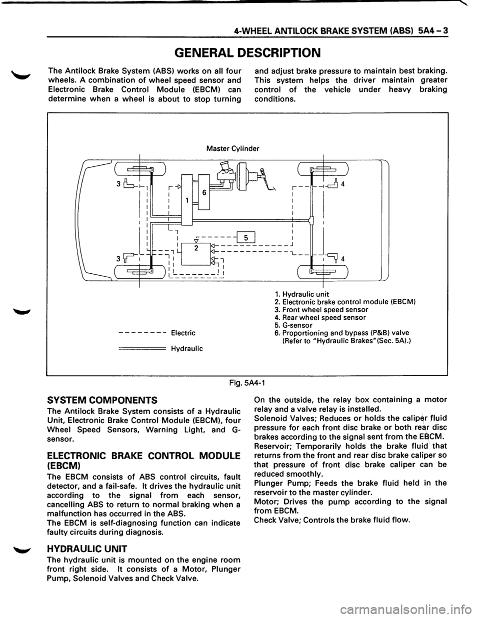
GENERAL DESCRIPTION
The Antilock Brake System (ASS) works on all four
wheels. A combination of wheel speed sensor and
Electronic Brake Control Module (EBCM) can
determine
when a wheel is about to stop turning
and adjust brake pressure to maintain best braking.
This system
helps the driver maintain greater
control of the vehicle under heavy braking
conditions.
Master Cylinder
I I I I
--------Electric
===== Hydraulic
,--1 I
I
I
-ld4
1. Hydraulic unit 2. Electronic brake control module (EBCM)
3. Front wheel speed sensor 4. Rear wheel speed sensor
5. G-sensor 6. Proportioning and bypass (P&Bl valve
(Refer to "Hydraulic Brakes"(Sec. 5A).)
Fig. 5A4-1
SYSTEM COMPONENTS
The Antilock Brake System consists of a Hydraulic
Unit, Electronic Brake Control Module (EBCM), four
Wheel Speed Sensors, Warning Light, and G
sensor.
ELECTRONIC BRAKE CONTROL MODULE
(EBCM)
The EBCM consists of ABS control circuits, fault
detector, and a fail-safe. It drives the hydraulic unit
according to the signal from each sensor,
cancelling ABS to return to normal braking when a
malfunction has occurred in the ABS.
The EBCM is self-diagnosing function can indicate
faulty circuits during diagnosis.
'--" HYDRAULIC UNIT
The hydraulic unit is mounted on the engine room
front right side. It consists of a Motor, Plunger
Pump, Solenoid Valves and Check Valve. On
the
outside, the relay box containing a motor
relay and a valve relay is installed.
Solenoid Valves;
Reduces or holds the calip~r fluid
pressure for each front disc brake or both rear disc
brakes according
to the signal sent from the EBCM.
Reservoir;
Temporarily holds the brake fluid that
returns from the front and rear disc brake caliper so
that pressure of front disc brake caliper can be
reduced
smoothly.
Plunger
Pump; Feeds the brake fluid held in the
reservoir
to the master cylinder.
Motor; Drives the pump according to the signal
from EBCM.
Check
Valve; Controls the brake fluid flow.
Page 416 of 1928
5A4-6 4-WHEEL ANTILOCK BRAKE SYSTEM (ABS)
If only rear wheels are rotated using jacks or
drum tester, the system will diagnose a speed
sensor
malfunction and the "ABS" warning
light will illuminate. But actually no trouble
exists. After inspection stop the engine once
and re-start it,
then make sure that the "ABS"
warning light does not illuminate.
If the battery has been discharged
The engine may stall if the battery has been
completely discharged and the engine is started via
a
jumper cable. This is because the Antilock Brake
System (ABS) requires a
large quantity of
electricity. In this case, wait until the battery is
recharged,
or set the ABS to a non-operative state
by removing the fuse for the ABS (40A). After the
battery has been recharged, stop the engine and
install the ABS fuse. Start the engine again, and
confirm that the ABS warning light does not light.
NOTE ON INTERMITTENTS
As with virtually any electronic system, it is difficult
to identify an intermittent failure. In such a case
duplicating the system malfunction during a test
drive
or a good description of vehicle behavior from
the customer may be helpful in locating a "most
likely" failed component or circuit. The symptom
diagnosis chart may also be useful in isolating the
failure. Most intermittent problems are caused by
faulty electrical connections or wiring. When an
intermittent failure is encountered, check suspect
circuits for:
Suspected harness damage.
• Poor mating of connector halves or terminals
not fully seated in the connector body (backed
out).
Improperly formed or damaged terminals.
TEST DRIVING ABS COMPLAINT
VEHICLES
In case that there has been an abnormality in the
lighting pattern of "ABS" warning light, the fault
can be located in accordance with the "DIAGNOSIS
BY 'ABS' WARNING LIGHT ILLUMINATION
PATTERN". In case of such trouble as can be
detected
by the driver as a vehicle symptom,
however, it is necessary to give a test drive
following the test procedure mentioned below,
thereby reproducing the symptom for trouble
diagnosis on a symptom basis:
1. Start the engine and make sure that the "ABS"
W/L goes OFF. If the W/L remains ON, it
means that the Diagnostic Trouble Code (DTC)
is stored. Therefore, read the code and
locate
the fault.
2. Start the vehicle and accelerate to 30 km/h (19
mph) or more.
3. Slowly brake and stop the vehicle completely.
4. Then restart the vehicle and accelerate to 40
km/h (25 mph) or more.
5. Brake at a time so as to actuate the ABS and ... ~
stop the vehicle.
6. Be cautious of abnormality during the test. If
theW/Lis actuated while driving, read the DTC
and locate the fault.
7. If the abnormality is not reproduced by the
test, make best efforts
to reproduce the
situation reported
by the customer.
8. If the abnormality has been detected, repair in
accordance
with the "SYMPTOM DIAGNOSIS".
NOTE:
Be sure to give a test drive on a wide, even
road
with a small traffic.
If an abnormality is detected, be sure to
suspend the test and start
trouble diagnosis at
once.
II ABS" WARNING LIGHT
When ABS trouble occurs to actuate "ABS"
warning light, the trouble code corresponding to
the trouble is stored in the EBCM. Only ordinary
brake is available with ABS being unactuated. Even
when "ABS" warning light is actuated, if the starter
switch is set
ON after setting it OFF once, the EBCM
checks
up on the entire system and, if there is no
abnormality, judges ABS to work currently and the
warning light is lit normally even though the
trouble code is stored.
NOTE:
Illumination of the "ABS" warning light
indicates that antilock braking is no longer
available. Power assisted braking without
antilock control is still available.
NORMAL OPERATION
II ABS" WARNING LIGHT
When the ignition is first moved from "OFF" to
"RUN", the amber "ABS" warning light will turn
"ON". The "ABS" warning light will turn "ON"
during engine starting and will usually stay "ON"
for approximately three seconds after the ignition
switch is returned to the "ON" position. The
warning light should remain "OFF" at all other
times.
•
Page 460 of 1928
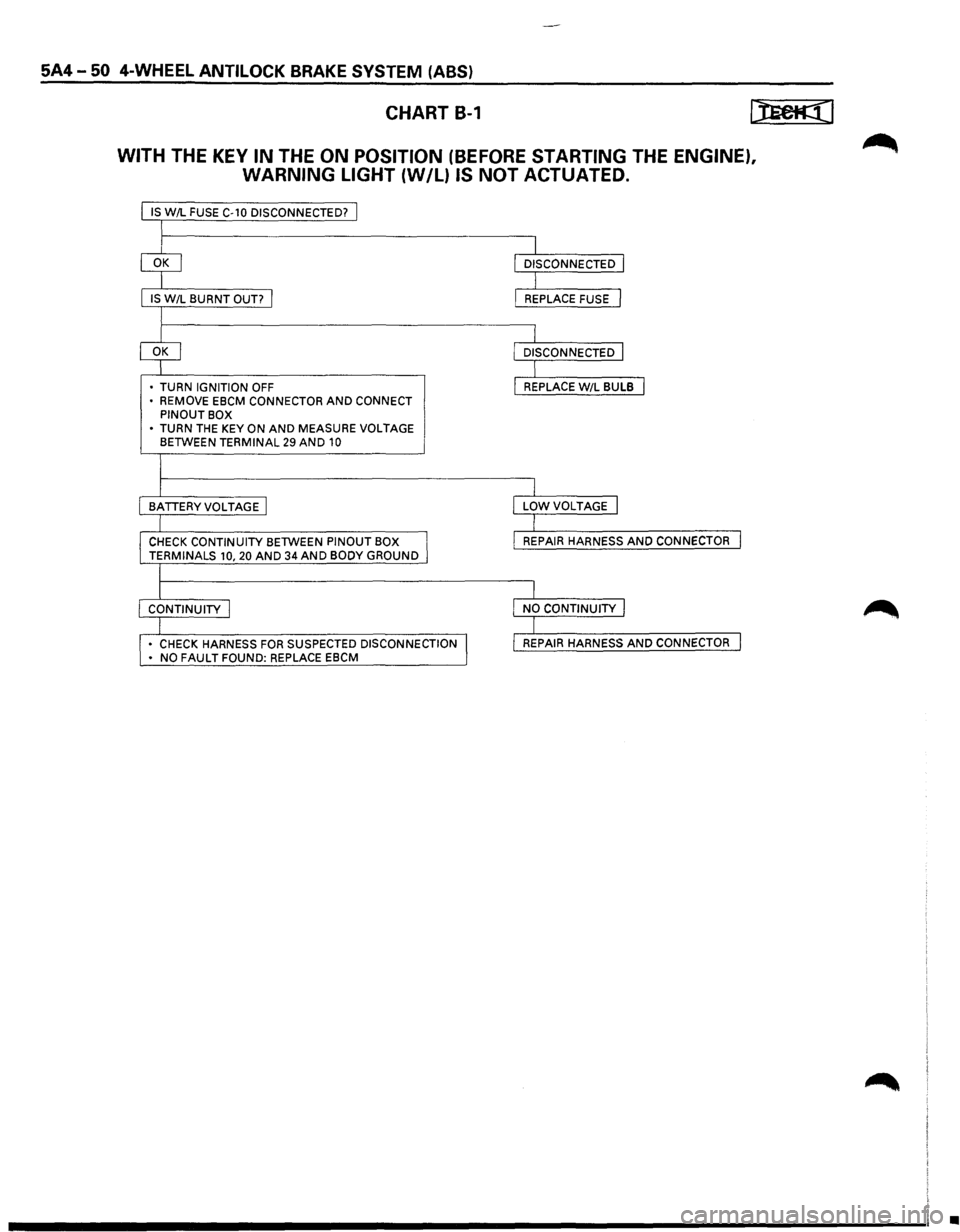
5A4-50 4-WHEEL ANTILOCK BRAKE SYSTEM (ABS)
CHART B-1
WITH THE KEY IN THE ON POSITION (BEFORE STARTING THE ENGINE),
WARNING LIGHT
{W/L) IS NOT ACTUATED.
IS W/L FUSE C-10 DISCONNECTED? j
I
IS W/L BURNT OUT? I
I
• TURN IGNITION OFF
• REMOVE EBCM CONNECTOR AND CONNECT PINOUT BOX
• TURN THE KEY ON AND MEASURE VOLTAGE BETWEEN TERMINAL 29 AND 10
I
I
BATTERYVOLTAGE I
I
CHECK CONTINUITY BETWEEN PINOUT BOX I TERMINALS 10, 20 AND 34 AND BODY GROUND
l
I CONTINUITY I
I • CHECK HARNESS FOR SUSPECTED DISCONNECTION I • NO FAULT FOUND: REPLACE EBCM
I
I
DISCONNECTED I
I L REPLACE FUSE J
I L DISCONNECTED J
I I REPLACE W/L BULB I
I
I
LOWVOLTAGE I
I
I
REPAIR HARNESS AND CONNECTOR I
I
I
NO CONTINUITY I
I I REPAIR HARNESS AND CONNECTOR I
•
Page 501 of 1928
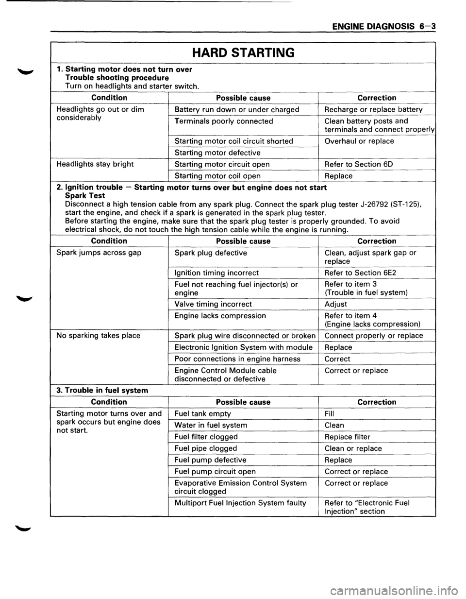
ENGINE DIAGNOSIS 6-3
HARD STARTING
1. Starting motor does not turn over
Trouble shooting procedure
Turn on headlights and starter switch.
Condition Possible cause Correction
Headlights go out or dim Battery run down or under charged Recharge or replace battery
considerably
Terminals poorly connected Clean battery posts and
terminals and connect properly
Starting motor coil circuit shorted Overhaul or replace
Starting motor defective
Headlights stay
bright Starting motor circuit open Refer to Section 6D
Starting
motor coil open Replace
2. Ignition trouble -Starting motor turns over but engine does not start
Spark Test
Disconnect a high tension cable from any spark plug. Connect the spark plug tester J-26792 (ST-1 25).
start the engine, and check if a spark is generated in the spark plug tester.
Before starting the engine, make sure
that the spark plug tester is properly grounded. To avoid
electrical shock, do not touch the high tension cable while the engine is running.
Condition Possible cause Correction
Spark jumps across gap
Spark plug defective Clean, adjust spark gap or
replace
Ignition
timing incorrect Refer to Section 6E2
Fuel not reaching fuel injector(s) or Refer to item 3
engine (Trouble
in
fuel system)
Valve
timing incorrect Adjust
Engine
lacks compression Refer to item 4
(Engine
lacks compression)
No sparking takes
place Spark plug wire disconnected or broken Connect properly or replace
Electronic Ignition System with module Replace
Poor connections in engine harness
Correct
Engine Control
Module cable Correct or replace
disconnected or defective
3. Trouble in fuel system
Condition Possible cause Correction
Starting motor turns over and
Fuel tank empty Fill
spark occurs but engine does
not start. Water in fuel system Clean
Fuel filter clogged Replace filter
Fuel pipe clogged Clean or replace
Fuel pump defective
Replace
Fuel
pump circuit open Correct or replace
Evaporative Emission Control System Correct or replace
circuit clogged
Multipart Fuel Injection System faulty Refer to "Electronic Fuel
Injection"
section
Page 525 of 1928
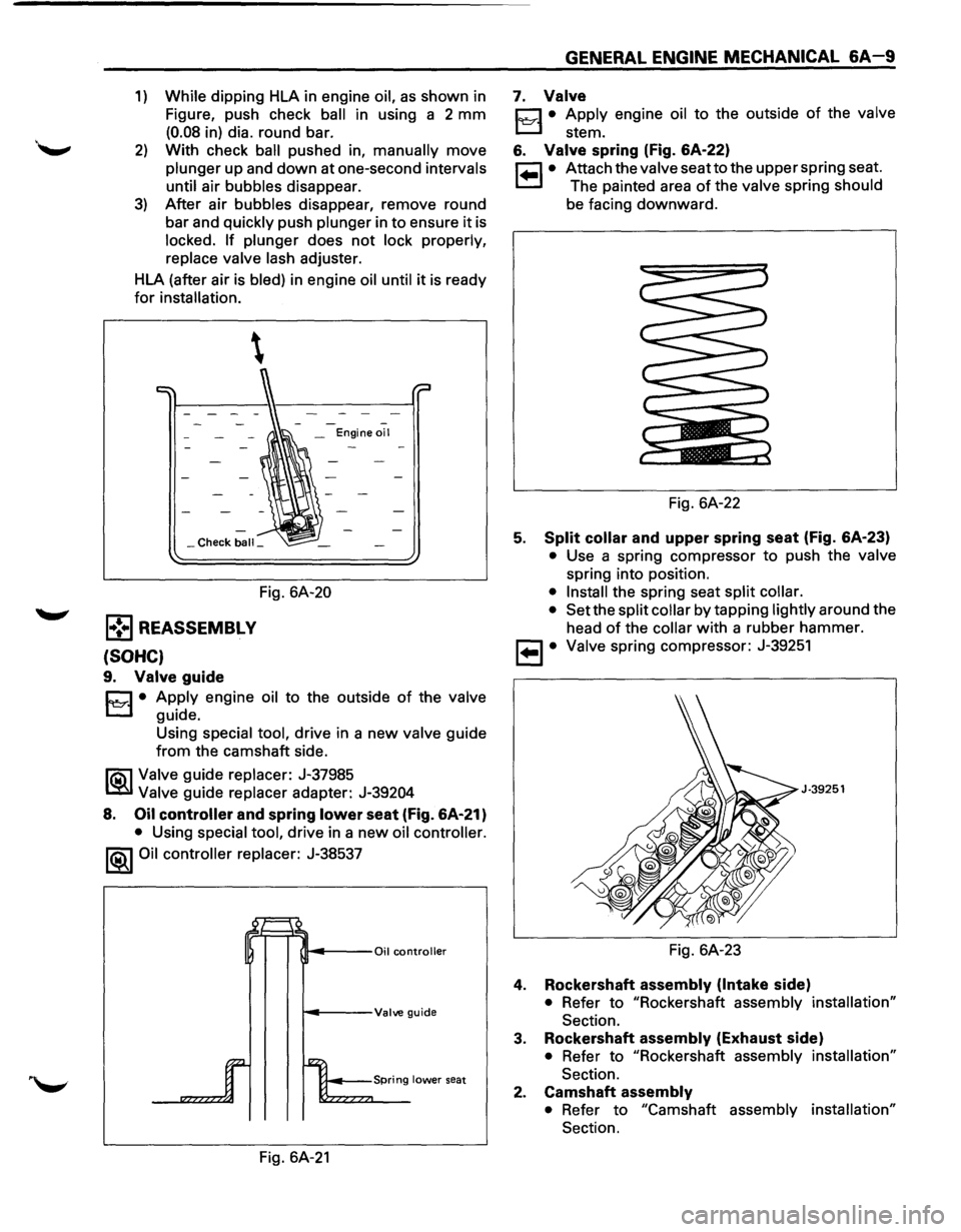
1) While dipping HLA in engine oil, as shown in
Figure, push check
ball in using a 2 mm
(0.08 in) dia. round bar.
2) With check ball pushed in, manually move
plunger up and down at one-second intervals
until
air bubbles disappear.
3) After air bubbles disappear, remove round
bar and
quickly push plunger in to ensure it is
locked. If plunger does not lock properly,
replace valve lash adjuster.
HLA (after air is
bled) in engine oil until it is ready
for installation.
-_ Engine oil
_Check ball_
Fig. 6A-20
l•!•l REASSEMBL V
(SOHC)
9. Valve guide
C1 • Apply engine oil to the outside of the valve
t..::::.l guide.
Using
special tool, drive in a new valve guide
from the camshaft side.
li5\l Valve guide replacer: J-37985
~ Valve guide replacer adapter: J-39204
8. Oil controller and spring lower seat (fig. 6A·21)
• Using special tool, drive in a new oil controller.
1®.1 Oil controller replacer: J-38537
~---Valve guide
Fig. 6A-21
GENERAL ENGINE MECHANICAL 6A-9
7. Valve
C1 • Apply engine oil to the outside of the valve
t..::::.l stem.
6. Valve spring (fig. 6A-22)
r=l • Attach the valve seatto the upper spring seat.
1.=.1 The painted area of the valve spring should
be facing downward.
Fig. 6A-22
5. Split collar and upper spring seat (Fig. 6A-23)
• Use a spring compressor to push the valve
spring into position.
• Install the spring seat split collar.
• Set
the split collar by tapping lightly around the
head
of the collar with a rubber hammer.
, ... ,. Valve spring compressor: J-39251
J·39251
Fig. 6A-23
4. Rockershaft assembly (Intake side)
• Refer to "Rockershaft assembly installation"
Section.
3. Rockershaft assembly (Exhaust side)
• Refer to "Rockershaft assembly installation"
Section.
2. Camshaft assembly
• Refer to "Camshaft assembly installation"
Section.