four wheel drive ISUZU TROOPER 1995 User Guide
[x] Cancel search | Manufacturer: ISUZU, Model Year: 1995, Model line: TROOPER, Model: ISUZU TROOPER 1995Pages: 1928
Page 1047 of 1928
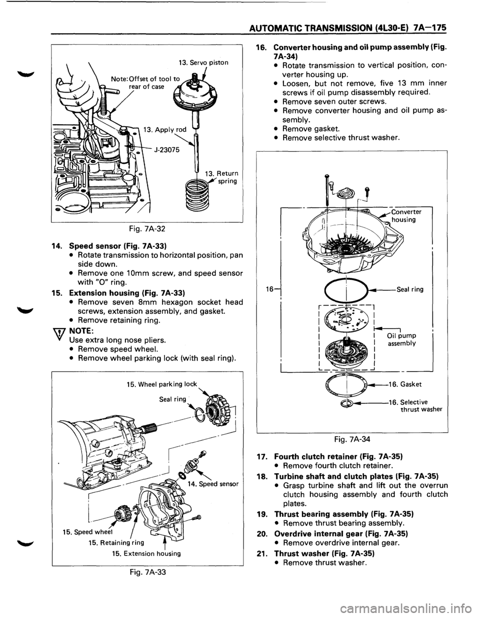
13. Servo piston
Fig. 7A-32
14. Speed sensor (Fig. 7A-33)
• Rotate transmission to horizontal position, pan
side down.
• Remove one 1 Omm screw, and speed sensor
with "0" ring.
15. Extension housing (Fig. 7 A-33)
• Remove seven 8mm hexagon socket head
screws, extension assembly, and gasket.
• Remove retaining ring.
\fl NOTE:
V Use extra long nose pliers.
• Remove speed wheel.
• Remove wheel parking lock (with seal ring).
15. Wheel parking lock
Seal:~
15. Retaining ring
15. Extension housing
Fig. 7A-33
AUTOMATIC TRANSMISSION (4L30-E) 7A-175
16. Converter housing and oil pump assembly (Fig.
7A-34)
16
• Rotate transmission to vertical position, con
verter housing up.
• Loosen, but not remove, five 13 mm inner
screws
if oil pump disassembly required.
• Remove seven outer screws.
• Remove converter housing and oil pump as
sembly.
• Remove gasket.
• Remove selective thrust washer.
~---16. Selective thrust washer
Fig. 7A-34
17. Fourth clutch retainer (Fig. 7A-35)
• Remove fourth clutch retainer.
18. Turbine shaft and clutch plates (Fig. 7A-35)
• Grasp turbine shaft and lift out the overrun
clutch housing assembly and fourth
clutch
plates.
19. Thrust bearing assembly (Fig. 7A-35)
• Remove thrust bearing assembly.
20. Overdrive internal gear (Fig. 7A-35)
• Remove overdrive internal gear.
21. Thrust washer (Fig. 7A-35)
• Remove thrust washer.
Page 1142 of 1928
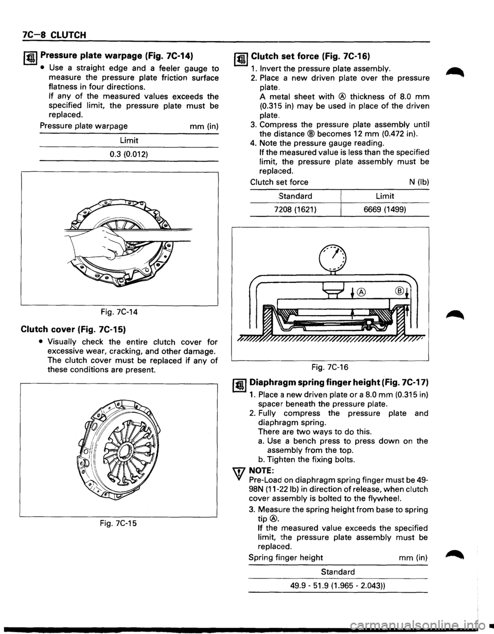
7C-8 CLUTCH
I~U Pressure plate warpage (fig. 7C-14)
• Use a straight edge and a feeler gauge to
measure the pressure plate friction surface
flatness in
four directions.
If any of the measured values exceeds the
specified limit, the pressure plate
must be
replaced.
Pressure plate warpage
Limit
0.3 (0.012)
Fig. 7C-14
Clutch cover (fig. 7C-15)
mm (in)
• Visually check the entire clutch cover for
excessive wear, cracking, and other damage.
The clutch cover
must be replaced if any of
these conditions are present.
Fig. 7C-15
jQI Clutch set force (Fig. 7C-16)
1. Invert the pressure plate assembly.
2. Place a new driven plate over the pressure
plate.
A metal sheet
with @ thickness of 8.0 mm
(0.315 in) may be used in place of the driven
plate
..
3. Compress the pressure plate assembly until
the
distance® becomes 12 mm (0.472 in).
4. Note the pressure gauge reading.
If the measured value is less than the specified
limit, the pressure plate assembly
must be
replaced.
Clutch set force N (lb)
Standard Limit
7:208 (1621) 6669 (1499)
Fig. 7C-16
1•1 Diaphragm spring finger height (fig. 7C-17)
1. Place a new driven plate or a 8.0 mm (0.315 in)
spacer beneath the pressure plate.
2. Fully compress the pressure plate and
diaphragm spring.
There are
two ways to do this.
a. Use a bench press to press down on the
asst~mbly from the top.
b. Tighten the fixing bolts.
IDNOTE:
Yf Pre-Load on diaphragm spring finger must be 49-
98N
(11-~~2 lb) in direction of release, when clutch
cover
assembly is bolted to the flywheel.
3. Measure the spring height from base to spring
tip@.
If the measured value exceeds the specified
limit, the pressure plate assembly
must be
replaced.
Spring finger height
mm (in)
Standard
49.9 -51.9 (1.965 -
2.043))
•
Page 1159 of 1928
TRANSFER CASE 7D-1
SECTION 70
TRANSFER CASE
w CAUTION:
When fasteners are removed, always reinstall them at the same location from which they were removed. If a
fastener needs
to be replaced, use the correct part number fastener for that application. If the correct part
number is not available, a fastener
of equal size and strength (or stronger) may be used. Fasteners that are
not reused, and those requiring thread locking compound, will
be called out. The correct torque values must
be used when installing fasteners that require torque.
If the above conditions are not followed, parts or
system damage could result.
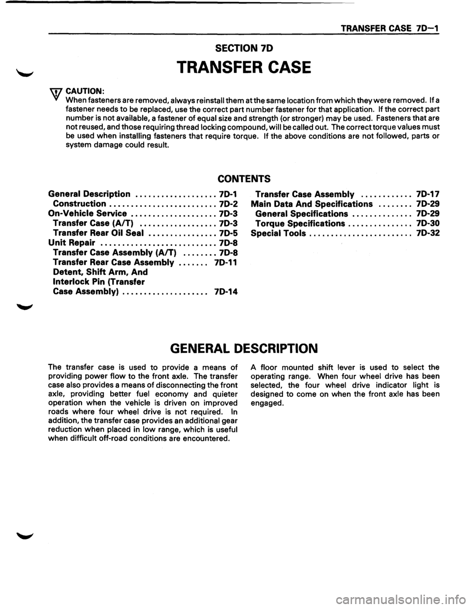
CONTENTS
General Description ................... 7D-1
Construction . . . . . . . . . . . . . . . . . . . . . . . . . 7D-2
On-Vehicle Service .................... 7D-3
Transfer
Case (A/T) .................. 7D-3
Transfer Rear
Oil Seal ................ 7D-5
Unit Repair ........................... 7D-8
Transfer
Case Assembly (AfT) ........ 7D-8
Transfer Rear
Case Assembly . .
. . . . . 7D-11
Detent, Shift Arm, And
Interlock Pin (Transfer
Case Assembly) . .
. . . . . . . . . . . . . . . . . . 7D-14 Transfer
Case
Assembly . .
. . . . . . . . . .
7D-17
Main Data And Specifications . . . . . . . .
70-29
General
Specifications . .
. . . . . . . . . . . .
70-29
Torque
Specifications ............... 7D-30
Special Tools
........................ 7D-32
GENERAL DESCRIPTION
The transfer case is used to provide a means of
providing power flow to the front axle. The transfer
case also provides a means of disconnecting the front
axle, providing better fuel economy and quieter
operation when the vehicle is driven
on improved
roads where four wheel drive is not required.
In
addition, the transfer case provides an additional gear
reduction when placed in low range, which
is useful
when difficult off-road conditions are encountered. A
floor mounted shift lever is used to select the
operating range. When four wheel drive has been
selected, the four wheel drive indicator light is
designed to come
on when the front axle has been
engaged.
Page 1199 of 1928
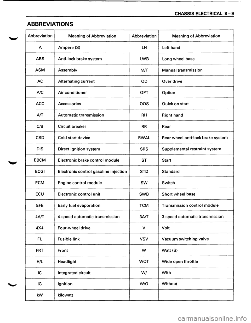
CHASSIS ELECTRICAL 8-9
ABBREVIATIONS
Abbreviation
Meaning of Abbreviation Abbreviation Meaning of Abbreviation
A Ampere
(S) LH Left
hand
ABS Anti-lock brake system LWB Long wheel base
ASM Assembly M!f Manual transmission
AC Alternating current OD Over drive
A/C
Air conditioner OPT Option
ACC Accessories QOS Quick on start
A/T Automatic
transmission
RH Right hand
C/8 Circuit
breaker
RR Rear
CSD Cold start device RWAL Rear
wheel anti-lock brake system
DIS Direct ignition system SRS Supplemental restraint system
EBCM Electronic brake control module
ST Start
ECGI Electronic control gasoline injection STD Standard
ECM Engine control module sw Switch
ECU Electronic control unit SWB Short wheel
base
EFE Early fuel evaporation TCM Transmission
control module
4A/T 4-speed
automatic transmission
3A/T 3-speed
automatic transmission
4X4 Four-wheel drive
v Volt
FL Fusible link vsv Vacuum switching valve
FRT Front w Watt {S)
H/L Headlight WOT Wide open throttle
IC Integrated circuit WI With
IG Ignition W/0 Without
kW
kilowatt
Page 1748 of 1928
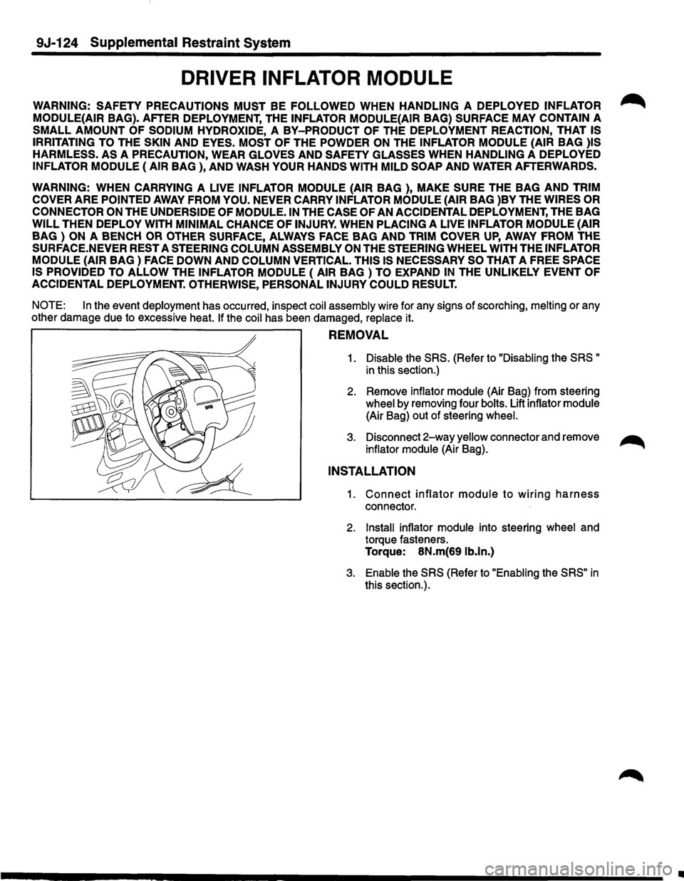
9J·124 Supplemental Restraint System
DRIVER INFLATOR MODULE
WARNING: SAFETY PRECAUTIONS MUST BE FOLLOWED WHEN HANDLING A DEPLOYED INFLATOR
MODULE(AIR
BAG). AFTER DEPLOYMENT, THE INFLATOR MODULE(AIR BAG} SURFACE MAY CONTAIN A
SMALL AMOUNT OF SODIUM HYDROXIDE, A BY-PRODUCT OF THE DEPLOYMENT REACTION, THAT IS
IRRITATING TO
THE SKIN AND EYES. MOST OF THE POWDER ON THE INFLATOR MODULE (AIR BAG )IS
HARMLESS.
AS A PRECAUTION, WEAR GLOVES AND SAFETY GLASSES WHEN HANDLING A DEPLOYED
INFLATOR MODULE (AIR BAG ), AND WASH YOUR HANDS WITH MILD SOAP AND WATER AFTERWARDS.
WARNING:
WHEN CARRYING A LIVE INFLATOR MODULE (AIR BAG }, MAKE SURE THE BAG AND TRIM
COVER
ARE POINTED AWAY FROM YOU. NEVER CARRY INFLATOR MODULE (AIR BAG )BY THE WIRES OR
CONNECTOR
ON THE UNDERSIDE OF MODULE. IN THE CASE OF AN ACCIDENTAL DEPLOYMENT, THE BAG
WILL THEN DEPLOY WITH MINIMAL CHANCE OF INJURY. WHEN PLACING A LIVE INFLATOR MODULE (AIR
BAG ) ON A BENCH OR OTHER SURFACE, ALWAYS FACE BAG AND TRIM COVER UP, AWAY FROM THE
SURFACE.NEVER REST A STEERING COLUMN ASSEMBLY ON THE STEERING WHEEL WITH THE INFLATOR
MODULE (AIR BAG } FACE DOWN AND COLUMN VERTICAL. THIS IS NECESSARY SO THAT A FREE SPACE
IS PROVIDED TO
ALLOW THE INFLATOR MODULE (AIR BAG} TO EXPAND IN THE UNLIKELY EVENT OF
ACCIDENTAL DEPLOYMENT. OTHERWISE, PERSONAL INJURY COULD RESULT.
NOTE:
In the event deployment has occurred, inspect coil assembly wire for any signs of scorching, melting or any
other damage due to excessive heat.
If the coil has been damaged, replace it.
REMOVAL
1. Disable the SRS. (Refer to "Disabling the SRS "
in this section.)
2. Remove inflator module (Air Bag) from steering
wheel by removing four bolts. Lift inflator module
(Air Bag) out of steering wheel.
3. Disconnect 2-way yellow connector and remove ~
inflator module (Air Bag).
INSTALLATION
1. Connect inflator module to wiring harness
connector.
2. Install inflator module into steering wheel and
torque fasteners.
Torque: 8N.m(69 lb.ln.)
3. Enable the SRS (Refer to "Enabling the SRS" in
this section.).
•