ignition ISUZU TROOPER 1995 Service Manual
[x] Cancel search | Manufacturer: ISUZU, Model Year: 1995, Model line: TROOPER, Model: ISUZU TROOPER 1995Pages: 1928
Page 422 of 1928
5A4-12 4-WHEEL ANTILOCK BRAKE SYSTEM (ABS)
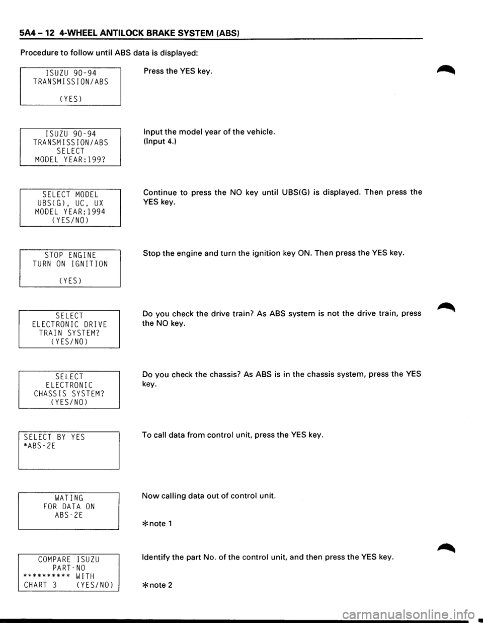
Procedure to follow until ABS data is displayed:
ISUZU 90-94
TRANSMISSION/ASS
C YES)
ISUZU 90-94
TRANSMISSION/ASS
SELECT
MODEL YEAR:l99?
SELECT MODEL
UBSCG), UC, UX
MODEL YEAR:l994
CYES/NO)
STOP ENGINE
TURN ON IGNITION
C YES)
SELECT
ELECTRONIC DRIVE
TRAIN SYSTEM?
CYES/NO)
SELECT
ELECTRONIC
CHASSIS SYSTEM?
CYES/NO)
SELECT BY YES
*ABS-2E
WATING
FOR DATA ON
ABS-2E
COMPARE ISUZU
PART-NO
********** WITH
CHART 3 CYES/NO)
Press the YES key.
Input the model year of the vehicle.
(Input
4.)
Continue to press the NO key until UBS(G) is displayed. Then press the
YES key.
Stop the engine and turn the ignition key
ON. Then press the YES key.
Do you check the drive train? As ABS system is
not the drive train, press
the
NO key.
Do you check the chassis? As ABS
is in the chassis system, press the YES
key.
To
call data from control unit, press the YES key.
Now calling data out of control unit.
Identify the part No. of the control unit, and then press the YES key.
Page 430 of 1928
5A4-20 4-WHEEL ANTILOCK BRAKE SYSTEM (ABS)
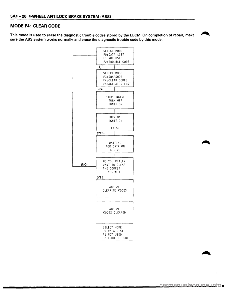
MODE F4: CLEAR CODE
This mode is used to erase the diagnostic trouble codes stored by the EBCM. On completion of repair, make ~
sure the ABS system works normally and erase the diagnostic trouble code by this mode.
SELECT MODE
FO:DATA LIST Fl: NOT USED
F2:TROUBLE CODE
(.!., i) I
SELECT MODE
F3:SNAPSHOT F4:CLEAR CODES F5:ACTUATOR TEST
(F4) L
STOP ENGINE TURN OFF
IGNITION
I
TURN ON
IGNITION
CYES)
(YES) I
WAITING FOR DATA ON ABS-2E
I
DO YOU REALLY !NO) WANT TO CLEAR
THE CODES? (YES/NO)
(YES) I
ABS-2E CLEARING CODES
I
ABS-2E CODES CLEARED
I
SELECT MODE FO: DATA LIST
Fl:NOT USED F2:TROUBLE CODE
•
Page 443 of 1928
4-WHEEL ANTILOCK BRAKE SYSTEM (ABS) 5A4-33
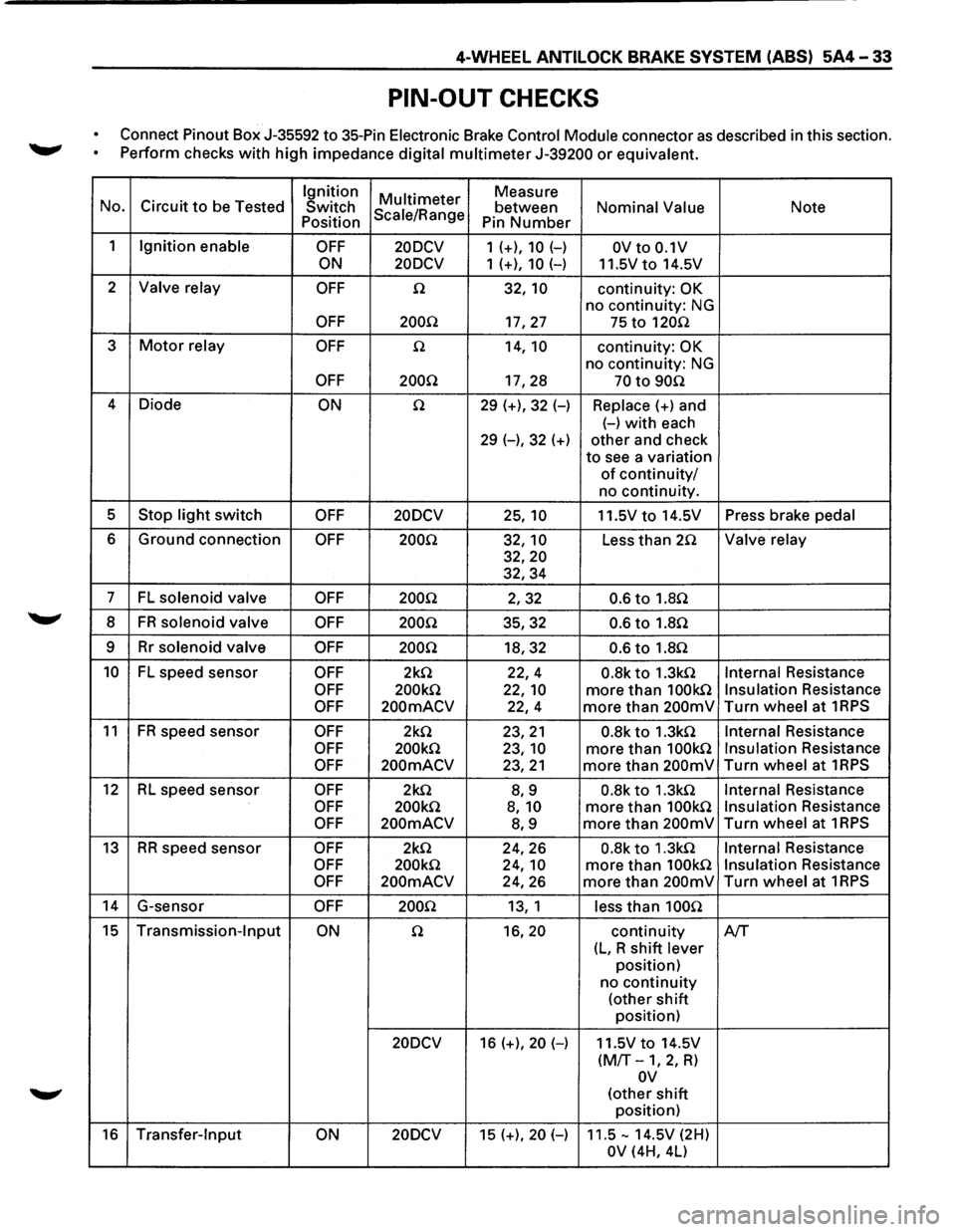
PIN-OUT CHECKS
Connect Pinout Box J-35592 to 35-Pin Electronic Brake Control Module connector as described in this section.
~ Perform checks with high impedance digital multimeter J-39200 or equivalent.
Ignition
Multi meter Measure
No. Circuit to be Tested
Switch Scale/Range between Nominal Value Note Position
Pin Number
1 Ignition enable OFF 20DCV 1 (+), 10 (-) OV to 0.1V
ON 20DCV
1 (+), 10 (-) 11.5Vto 14.5V
2
Valve relay OFF n 32, 10 continuity: OK
no continuity: NG
OFF 200.Q 17,27 75 to 120n
3 Motor relay OFF n 14, 10 continuity: OK
no continuity: NG
OFF 200Q 17,28 70 to 90n
4
Diode ON n 29 (+), 32 (-) Replace(+) and
(-)with each
29 (-), 32 (+) other and check
to see a variation
of continuity/
no continuity.
5
Stop light switch OFF 20DCV 25, 10 11.5V to 14.5V Press brake pedal
6 Ground connection OFF 200Q 32, 10 Less than 2.Q Valve relay
32,20
32,34
7 FL solenoid valve OFF 200Q 2,32 0.6 to 1.8Q
8 FR solenoid valve OFF 200Q 35,32 0.6 to 1.8n
9 Rr solenoid valve OFF 200Q 18,32 0.6 to 1.8n
10 FL speed sensor OFF 2k.Q 22,4 0.8k to 1.3kn Internal Resistance
OFF 200k.Q 22, 10 more than 100kn Insulation Resistance
OFF 200mACV 22,4 more than 200mV Turn wheel at 1RPS
11 FR speed
sensor OFF 2k.Q 23,21 0.8k to 1.3k.Q Internal Resistance
OFF 200k.Q 23, 10 more than 100k.Q Insulation Resistance
OFF 200mACV 23,21 more than 200mV Turn wheel at 1RPS
12 RL speed sensor OFF 2k.Q 8,9 0.8k to 1.3k.Q Internal Resistance
OFF 200k.Q 8, 10 more than 100k.Q Insulation Resistance
OFF 200mACV 8,9 more than 200mV Turn wheel at 1RPS
13 RR speed sensor OFF 2k.Q 24,26 0.8k to 1.3k.Q Internal Resistance
OFF 200k.Q 24, 10 more than 100k.Q Insulation Resistance
OFF 200mACV 24,26 more than 200mV Turn wheel at 1RPS
14 G-sensor OFF 200.Q 13, 1 less than 100n
15 Transmission-Input ON n 16,20 continuity A/T
(L, R shift lever
position)
no
continuity
(other shift
position)
20DCV 16 (+), 20 (-) 11.5V to 14.5V
(M/T-1, 2, R)
ov
(other shift
position)
16 Transfer-Input ON 20DCV 15 (+), 20 (-) 11.5-14.5V (2H)
OV (4H, 4L)
Page 454 of 1928
5A4-44 4-WHEEL ANTILOCK BRAKE SYSTEM (ASS)
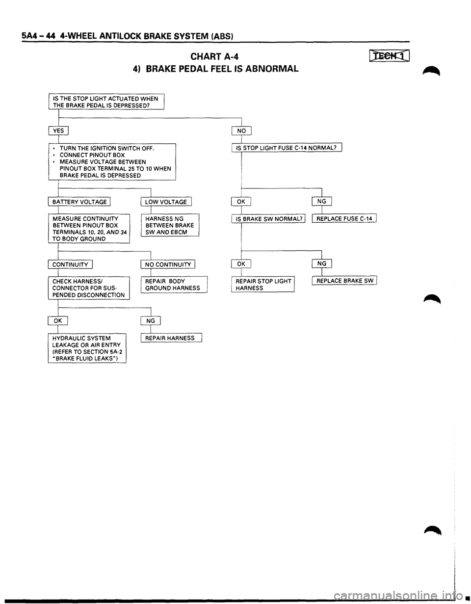
CHART A-4
4) BRAKE PEDAL
FEEL IS ABNORMAL
IS THE STOP LIGHT ACTUATED WHEN
THE BRAKE PEDAL IS DEPRESSED?
TURN THE
IGNITION SWITCH OFF.
CONNECT PINOUT BOX
MEASURE VOLTAGE BETWEEN PINOUT BOX TERMINAL 25 TO 10 WHEN
BRAKE PEDAL IS DEPRESSED
MEASURE CONTINUITY BETWEEN PINOUT BOX
TERMINALS 10, 20, AND 34 TO BODY GROUND
CHECK HARNESS/
CONNECTOR
FOR SUSPENDED DISCONNECTION
HYDRAULIC SYSTEM
LEAKAGE OR AIR ENTRY (REFER TO SECTION 5A-2
"BRAKE FLUID LEAKS") HARNESS
NG
BETWEEN BRAKE
SWANDEBCM
•
Page 460 of 1928
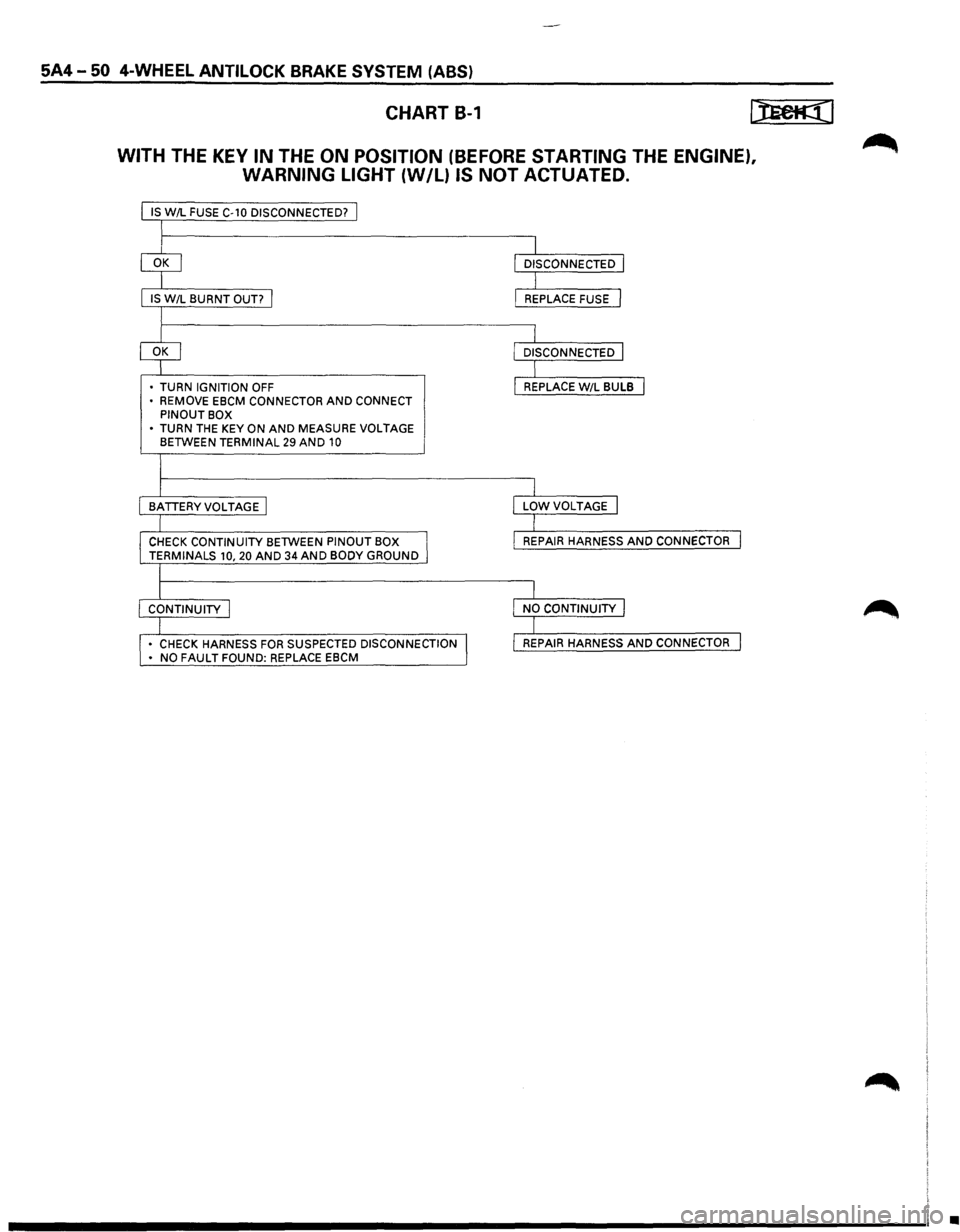
5A4-50 4-WHEEL ANTILOCK BRAKE SYSTEM (ABS)
CHART B-1
WITH THE KEY IN THE ON POSITION (BEFORE STARTING THE ENGINE),
WARNING LIGHT
{W/L) IS NOT ACTUATED.
IS W/L FUSE C-10 DISCONNECTED? j
I
IS W/L BURNT OUT? I
I
• TURN IGNITION OFF
• REMOVE EBCM CONNECTOR AND CONNECT PINOUT BOX
• TURN THE KEY ON AND MEASURE VOLTAGE BETWEEN TERMINAL 29 AND 10
I
I
BATTERYVOLTAGE I
I
CHECK CONTINUITY BETWEEN PINOUT BOX I TERMINALS 10, 20 AND 34 AND BODY GROUND
l
I CONTINUITY I
I • CHECK HARNESS FOR SUSPECTED DISCONNECTION I • NO FAULT FOUND: REPLACE EBCM
I
I
DISCONNECTED I
I L REPLACE FUSE J
I L DISCONNECTED J
I I REPLACE W/L BULB I
I
I
LOWVOLTAGE I
I
I
REPAIR HARNESS AND CONNECTOR I
I
I
NO CONTINUITY I
I I REPAIR HARNESS AND CONNECTOR I
•
Page 461 of 1928
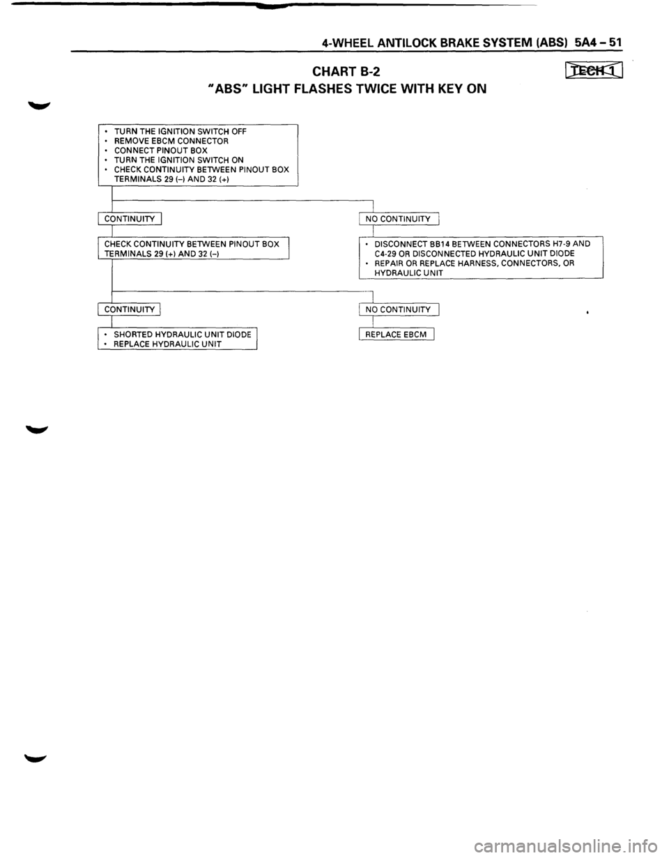
4-WHEEL ANTILOCK BRAKE SYSTEM (ABS) 5A4-51
CHART B-2 [JECK¢(1
II ABS11 LIGHT FLASHES TWICE WITH KEY ON
• TURN THE IGNITION SWITCH OFF • REMOVE EBCM CONNECTOR
• CONNECT PINOUT BOX
• TURN THE IGNITION SWITCH ON CHECK CONTINUITY BETWEEN PINOUT BOX
TERMINALS 29 HAND 32 (+)
I CONTINUITY I NO CONTINUITY I
I CHECK CONTINUITY BETWEEN PINOUT BOX
I
DISCONNECT BB14 BETWEEN CONNECTORS H7-9 AND TERMINALS 29 (+)AND 32 H C4-29 OR DISCONNECTED
HYDRAULIC UNIT DIODE
• REPAIR OR REPLACE HARNESS, CONNECTORS, OR HYDRAULIC UNIT
I CONTINUITY I NO CONTINUITY I .
I • SHORTED HYDRAULIC UNIT DIODE I REPLACE EBCM I • REPLACE HYDRAULIC UNIT
Page 462 of 1928
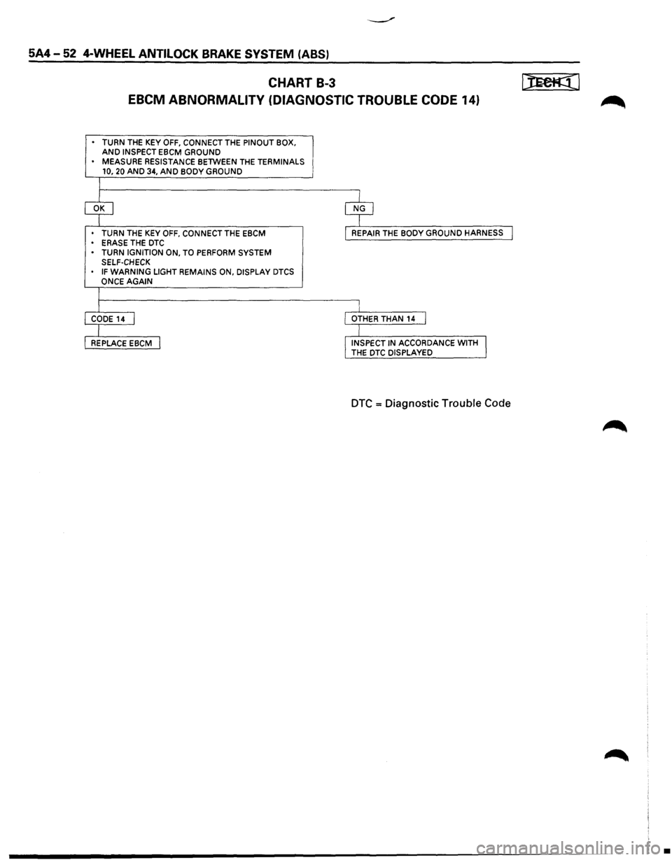
5A4-52 4-WHEEL ANTILOCK BRAKE SYSTEM (ABS)
CHART B-3 ~I
EBCM ABNORMALITY (DIAGNOSTIC TROUBLE CODE 14)
• TURN THE KEY OFF, CONNECT THE PINOUT BOX. AND INSPECT EBCM GROUND
• MEASURE RESISTANCE BETWEEN THE TERMINALS
10, 20 AND 34, AND BODY GROUND
T
~ $
• TURN THE KEY OFF, CONNECT THE EBCM
• ERASE THE DTC I REPAIR THE BODY GROUND HARNESS I
• TURN IGNITION ON, TO PERFORM SYSTEM
SELF-CHECK
IF WARNING LIGHT REMAINS ON, DISPLAY DTCS
ONCE AGAIN
I
r I CODE14 I I OTHER THAN
14 I
I I
REPLACE EBCM I !INSPECT IN ACCORDANCE WITH I THE DTC DISPLAYED
DTC = Diagnostic Trouble Code
•
Page 491 of 1928
PARKING BRAKES 5C-1
SECTION 5C
PARKING BRAKES
'\f7 CAUTION:
Yf All brake attaching fasteners are an important attaching part in that they could affect performance of vital
parts and systems, and/or could result in major repair expense. They must be replaced with one ofthe same
part number
or with and equivalent part if replacement becomes necessary. Do not use replacement parts of
lesser quality or substitute design. Torque values must be used as specified during reassembly to assure
proper retention
of these parts.
CONTENTS
General Description ..................... 5C-1
Operation . . . . . . . . . . . . . . . . . . . . . . . . . . . . . 5C-2
On-Vehicle Service
..................... 5C-3
Parking Brake Lever Replacement . .
. . . . .
5C-3
Parking Brake Front Cable . .
. . . . . . . . . . .
5C-4
Parking Brake Rear Cable . .
. . . . . . . . . . . .
5C-5
Parking Brake Lining Inspection ......... 5C-6
Parking Brake Rotor (Drum) Inspection ... 5C-6
Parking Brake Adjustment .............. 5C-7
Main Data and Specifications ............. 5C-8
General
Specifications ................. 5C-8
Torque Specifications ................. 5C-8
GENERAL DESCRIPTION
Pulling up the parking brake lever by hand will set the
parking brake.
Once pulled up, the lever is held by a
ratchet type
lock until it is released. The position of the
lever is transmitted through cable/lever systems to the
rear
wheels. These parts are designed to obtain
sufficient braking force
when parking on slopes. When
the parking brake is set,
or when the ignition SW is in
the
"ON" position, the brake warning light illuminates.
The rear wheel parking brake is a duo-servo brake
(mechanical inside expansion type) built in to the rear
disc brake. Parking brake adjustment is made through
the adjusting
hole (bored through back plate). Parking
brake
lever stroke should be adjusted to 6 or 7
notches. Refer
to "Parking Brake Adjustment" in
this Section.
Page 499 of 1928
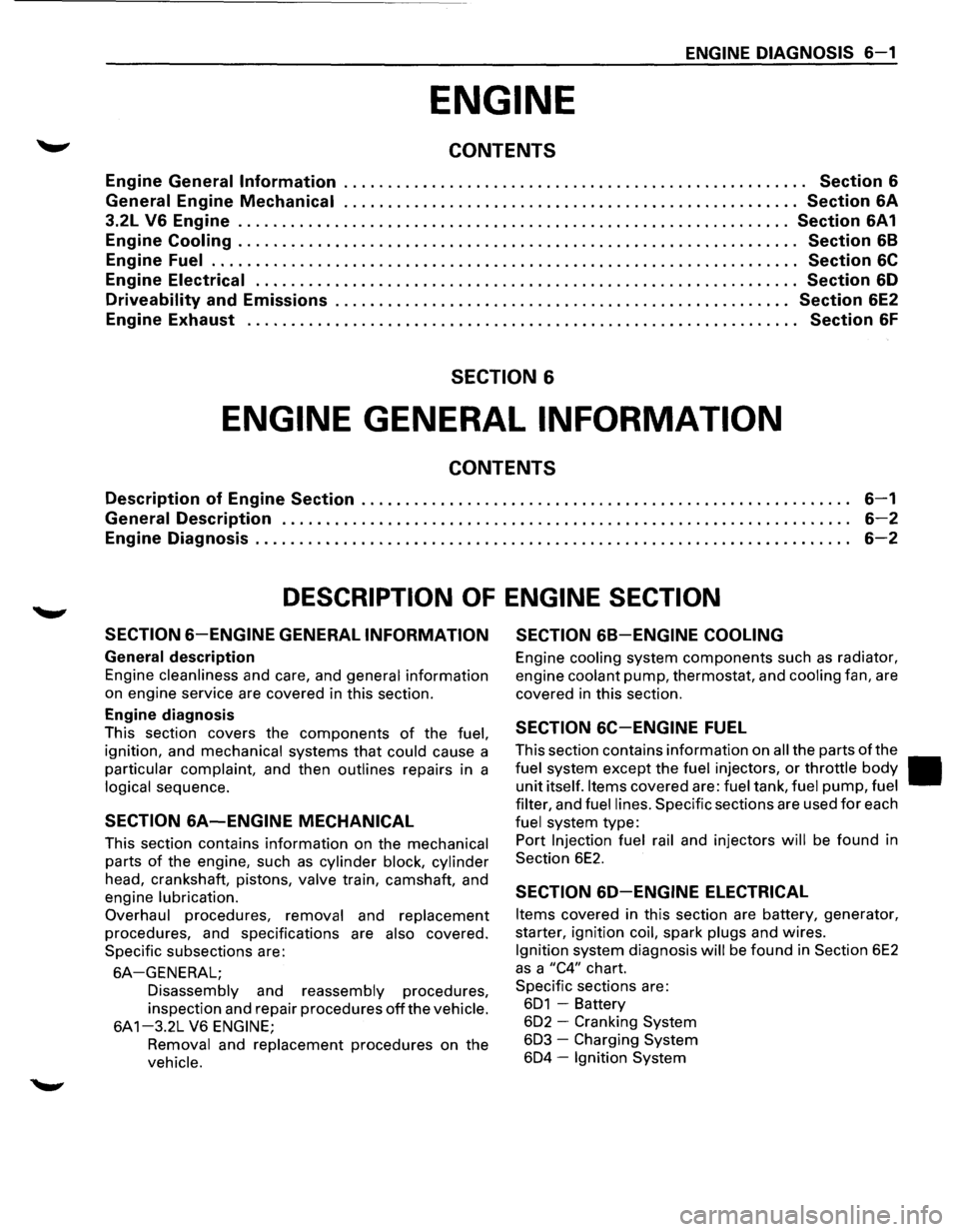
ENGINE DIAGNOSIS S-1
ENGINE
CONTENTS
Engine General Information . . . . . . . . . . . . . . . . . . . . . . . . . . . . . . . . . . . . . . . . . . . . . . . . . . . . . Section S
General
Engine Mechanical .................................................... Section SA
3.2L VS Engine ............................................................... Section SA1
Engine Cooling . . . . . . . . . . . . . . . . . . . . . . . . . . . . . . . . . . . . . . . . . . . . . . . . . . . . . . . . . . . . . . . . Section S8
Engine Fuel . . . . . . . . . . . . . . . . . . . . . . . . . . . . . . . . . . . . . . . . . . . . . . . . . . . . . . . . . . . . . . . . . . . Section SC
Engine Electrical . . . . . . . . . . . . . . . . . . . . . . . . . . . . . . . . . . . . . . . . . . . . . . . . . . . . . . . . . . . . . . Section SD
Driveability and Emissions . . . . . . . . . . . . . . . . . . . . . . . . . . . . . . . . . . . . . . . . . . . . . . . . . . . . Section SE2
Engine Exhaust . . . . . . . . . . . . . . . . . . . . . . . . . . . . . . . . . . . . . . . . . . . . . . . . . . . . . . . . . . . . . . . Section SF
SECTION 6
ENGINE GENERAL INFORMATION
CONTENTS
Description of Engine Section . . . . . . . . . . . . . . . . . . . . . . . . . . . . . . . . . . . . . . . . . . . . . . . . . . . . . . . . S-1
General Description . . . . . . . . . . . . . . . . . . . . . . . . . . . . . . . . . . . . . . . . . . . . . . . . . . . . . . . . . . . . . . . . . S-2
Engine Diagnosis . . . . . . . . . . . . . . . . . . . . . . . . . . . . . . . . . . . . . . . . . . . . . . . . . . . . . . . . . . . . . . . . . . . . S-2
DESCRIPTION OF ENGINE SECTION
SECTIONS-ENGINE GENERAL INFORMATION SECTION S8-ENGINE COOLING
General description
Engine cleanliness and care, and general information
on engine service are covered in this section.
Engine diagnosis
This section covers the components of the fuel,
ignition, and mechanical systems that could cause a
particular complaint, and then outlines repairs in a
logical sequence.
SECTION SA-ENGINE MECHANICAL
This section contains information on the mechanical
parts of the engine, such as cylinder block, cylinder
head, crankshaft, pistons, valve train, camshaft, and
engine
lubrication.
Overhaul
procedures, removal and replacement
procedures, and specifications are also covered.
Specific subsections are:
SA-GENERAL;
Disassembly and reassembly procedures,
inspection and repair procedures
off the vehicle.
6A 1-3.2L V6 ENGINE;
Removal
and replacement procedures on the
vehicle.
Engine cooling system components such as radiator,
engine
coolant pump, thermostat, and cooling fan, are
covered
in this section.
SECTION SC-ENGINE FUEL
This section contains information on all the parts of the
fuel system except the fuel injectors, or throttle body II
unit itself. Items covered are: fuel tank, fuel pump, fuel
filter,
and fuel lines. Specific sections are used for each
fuel system type:
Port
Injection fuel rail and injectors will be found in
Section
6E2.
SECTION SD-ENGINE ELECTRICAL
Items covered in this section are battery, generator,
starter, ignition
coil, spark plugs and wires.
Ignition system diagnosis will be found in Section 6E2
as a "C4" chart.
Specific sections are:
601 -Battery
602 - Cranking System
603 -Charging System
604 -Ignition System
Page 501 of 1928
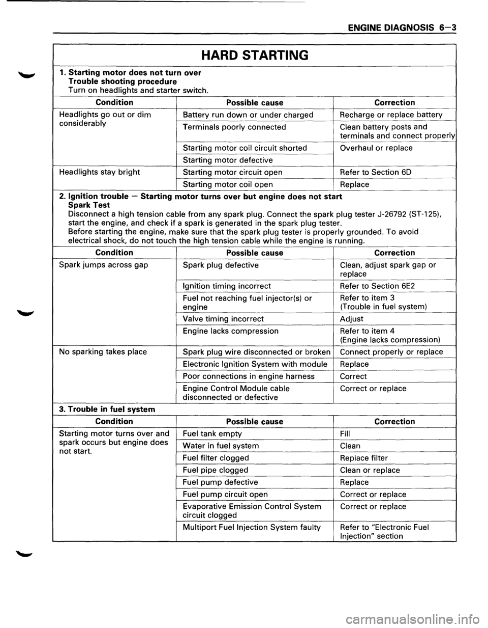
ENGINE DIAGNOSIS 6-3
HARD STARTING
1. Starting motor does not turn over
Trouble shooting procedure
Turn on headlights and starter switch.
Condition Possible cause Correction
Headlights go out or dim Battery run down or under charged Recharge or replace battery
considerably
Terminals poorly connected Clean battery posts and
terminals and connect properly
Starting motor coil circuit shorted Overhaul or replace
Starting motor defective
Headlights stay
bright Starting motor circuit open Refer to Section 6D
Starting
motor coil open Replace
2. Ignition trouble -Starting motor turns over but engine does not start
Spark Test
Disconnect a high tension cable from any spark plug. Connect the spark plug tester J-26792 (ST-1 25).
start the engine, and check if a spark is generated in the spark plug tester.
Before starting the engine, make sure
that the spark plug tester is properly grounded. To avoid
electrical shock, do not touch the high tension cable while the engine is running.
Condition Possible cause Correction
Spark jumps across gap
Spark plug defective Clean, adjust spark gap or
replace
Ignition
timing incorrect Refer to Section 6E2
Fuel not reaching fuel injector(s) or Refer to item 3
engine (Trouble
in
fuel system)
Valve
timing incorrect Adjust
Engine
lacks compression Refer to item 4
(Engine
lacks compression)
No sparking takes
place Spark plug wire disconnected or broken Connect properly or replace
Electronic Ignition System with module Replace
Poor connections in engine harness
Correct
Engine Control
Module cable Correct or replace
disconnected or defective
3. Trouble in fuel system
Condition Possible cause Correction
Starting motor turns over and
Fuel tank empty Fill
spark occurs but engine does
not start. Water in fuel system Clean
Fuel filter clogged Replace filter
Fuel pipe clogged Clean or replace
Fuel pump defective
Replace
Fuel
pump circuit open Correct or replace
Evaporative Emission Control System Correct or replace
circuit clogged
Multipart Fuel Injection System faulty Refer to "Electronic Fuel
Injection"
section