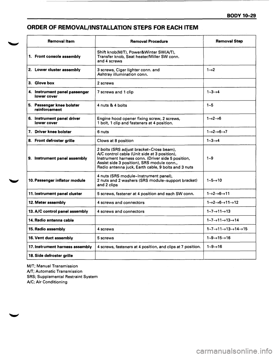
ORDER OF REMOVAL/INSTALLATION STEPS FOR EACH ITEM
Removal Item
1. Front console assembly
2. Lower cluster assembly
3. Glove box
4. Instrument panel passenger lower cover
5. Passenger knee bolster reinforcement
6. Instrument panel driver lower cover
7. Driver knee bolster
8. Front defroster grille
9. Instrument panel assembly
10. Passenger inflator module
11.1nstrument panel cluster
12. Meter assembly
13. A/C control panel assembly
14. Radio antenna cable
15. Radio assembly
16. Vent duct assembly
17 .Instrument harness assembly
18. Side defroster grille
MfT; Manual Transmission
A/T;
Automatic Transmission Removal
Procedure
Shift
knob(MfT), Power&Winter SW(A/T),
Transfer knob, Seat heater/Miller SW conn.
and 4 screws
3 screws, Ciger lighter conn. and
Ashtray illumination conn.
2 screws
7 screws and 1 clip
4 nuts & 4 bolts
Engine hood opener fixing screw, 2 screws, 1 bolt, 1 clip and fasteners at 4 position.
6 nuts
Claws at 8 position
2 bolts (SRS adjust bracket-Cross beam), A!C control cable (Unit side at 3 position), Instrument harness conn. (Driver side 5 position,
Assist side 3 position), SRS module conn.,
Radio antenna juck, Earth
cable, 9 bolts and 3 nuts
4 nuts (SRS module-Instrument panel), 2 nuts and 2 washers (SRS module-support bracket)
and 2 clips
5 screws, fastener at 4 position and each SW conn.
4 screws and connectors
4 screws and connectors
4 screws
5 screws
4 screws, fasteners at 4 position, and clips at 7 position.
SRS; Supplemental Restraint System
A!C; Air Conditioning
BODY 10-29
Removal Step
1~2
1~3~4
1~5
1~2~6
1~2~6~7
1-3~4
1~9
1-5~10
1~2~6~11
1~2~6~11~12
1-7~11~13
1-7~11~13~14
1~7~11~13~14~15
1-9~15~16
1-9~16