seat memory ISUZU TROOPER 1995 Workshop Manual
[x] Cancel search | Manufacturer: ISUZU, Model Year: 1995, Model line: TROOPER, Model: ISUZU TROOPER 1995Pages: 1928
Page 786 of 1928
6E2-90 DRIVEABILITY AND EMISSIONS
INTERMITTENTS
Definition: Problem may or may not turn "ON" the
"Check Engine" malfunction indicator lamp or store
Diagnostic
Trouble Code (DTC).
DO NOT use the DTC charts in "Engine Components/
Wiring Diagrams/Diagnostic
Charts," Section "6E2-A"
for intermittent problem. The fault must be present to
locate the problem. If a fault is intermittent, use of DTC
charts may result in replacement of good parts.
•
• Most intermittent problems are caused by faulty
electrical
connections or wiring. Perform careful
visual/physical
check as described at start of
"Symptoms," Section "6E2-B." Check for:
Poor mating
of the connector halves. or
terminal not fully seated in the connector body
(backed out).
Improperly formed or damaged terminal. All
connector
terminals in the problem circuit
should be carefully reformed or replaced to
insure proper contact tension.
Poor
terminal to wire connection. This
requires removing the
terminal from the
connector body to check. Refer to
SECTION 8
"Wiring Harness Service,"
If a visual/physical check does not find the cause
of the problem, the car can be driven with a
voltmeter connected to a suspected circuit. A
"Scan tool" can also be used to help detect
intermittent conditions. An abnormal
voltage, or
"Scan" tool reading, when the problem occurs,
indicates the
problem may be in that circuit. If the wiring
and connectors check
OK, and a DTC was
stored
for a circuit having a sensor, except for
DTC(s) 44 and 45, substitute a known good sensor
and recheck.
• Loss of DTC memory. To check, disconnect
throttle position (TP) sensor and idle engine until
"Check
Engine" malfunction indicator lamp comes
"ON". DTC 21 should be stored, and kept in
memory when ignition is turned "OFF". If not, the
Engine
Control Module (ECM) is faulty.
•
An intermittent "Check Engine" malfunction
indicator
lamp with no stored DTC may be caused
by:
Ignition coil shorted to ground and arcing at
spark
plug wires or plugs.
"Check
Engine" malfunction indicator lamp
wire to ECM shorted to ground.
Diagnostic
"test" terminal wire to ECM,
shorted to ground.
ECM grounds, refer to ECM wiring diagrams.
• Check for an electrical system interference caused
by a defective
relay, ECM driven solenoid, or
switch. They can cause a sharp electrical surge.
Normally, the problem will occur when the faulty
component is operated.
• Check for improper installation of electrical
options such as lights, 2 way radios, etc.
• Ignition control wires should be routed away from
spark plug wires, electronic ignition (EI) wires, El
housing, coil and generator. Ground wire from
ECM to El should have a good connection.
• If problem has not been found, refer to "ECM
Connector Symptom" charts at the end of
"Symptoms," Section "6E2-B."
HARD START
Definition: Engine cranks OK, but does not start for a
long time. Does eventually run, or may
start
but immediately dies.
PRELIMINARY CHECKS
• Perform the careful visual/physical checks as
described at start of "Symptoms," Section "6E2-
B".
•
Make sure the driver is using the correct starting
procedure.
SENSORS
• CHECK: Engine coolant temperature sensor using
a
"Scan tool", compare engine coolant
temperature with ambient temperature
on
cold engine. -
If engine coolant temperature
readings
is 5 degrees greater than or less than
ambient air temperature on a
cold
engine, check resistance in engine
coolant temperature sensor circuit
or
sensor itself. Compare engine coolant
temperature sensor resistance value
to the "Diagnostic Aids" chart on
DTC
14 chart.
• CHECK: Manifold absolute pressure sensor.
Check for flooding and/or correct sensor
for vehicle.
• CHECK: TP sensor for binding or a high TP sensor
voltage with the throttle closed (should
read between 0.54 volt and 1.25 volts.)
Page 816 of 1928
6E2 120 DRIVEABILITY AND EMISSIONS
THROTTLE BODY (TB) ASSEMBLY
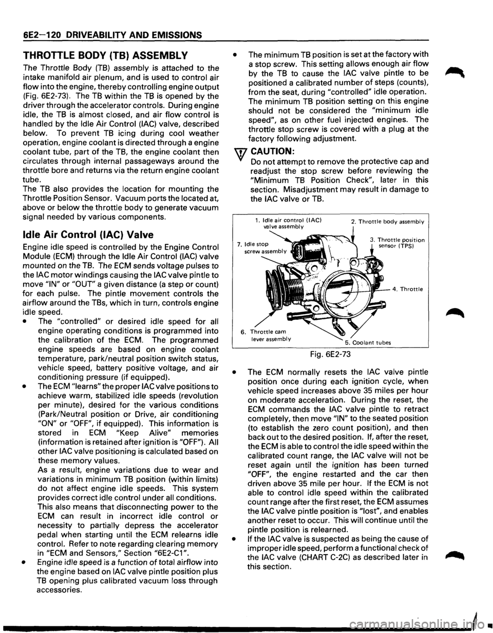
The Throttle Body (TB) assembly is attached to the
intake manifold air
plenum, and is used to control air
flow into the engine, thereby controlling engine output
(Fig. 6E2-73). The TB within the TB is opened by the
driver through the accelerator controls. During engine
idle, the
TB is almost closed, and air flow control is
handled by the Idle Air Control (lAC) valve, described
below. To prevent
TB icing during cool weather
operation, engine
coolant is directed through a engine
coolant tube, part
of the TB, the engine coolant then
circulates through internal passageways around the
throttle bore and returns via the return engine coolant
tube.
The
TB also provides the location for mounting the
Throttle Position
Sensor. Vacuum ports the located at,
above or
below the throttle body to generate vacuum
signal needed
by various components.
Idle Air Control (lAC) Valve
Engine idle speed is controlled by the Engine Control
Module (ECM) through the Idle Air Control (lAC) valve
mounted on the
TB. The ECM sends voltage pulses to
the lAC motor windings causing the lAC valve pintle to
move "IN" or "OUT" a given distance (a step or count)
for each pulse. The pintle movement controls the
airflow around the TBs, which in turn, controls engine
idle speed.
• The "controlled" or desired idle speed for all
engine operating conditions is programmed into
the
calibration of the ECM. The programmed
engine speeds are based on engine coolant
temperature, park/neutral position switch status,
vehicle speed, battery positive voltage, and air
conditioning pressure (if equipped).
• The ECM "learns" the proper lAC valve positions to
achieve warm, stabilized idle speeds (revolution
per minute), desired
for the various conditions
(Park/Neutral position
or Drive, air conditioning
"ON" or "OFF", if equipped). This information is
stored in
ECM "Keep Alive" memories
(information
is retained after ignition is "OFF"). All
other lAC valve positioning is calculated based on
these
memory values.
As a
result, engine variations due to wear and
variations in
minimum TB position (within limits)
do not affect engine idle speeds. This system
provides correct idle control under
all conditions.
This also means
that disconnecting power to the
ECM can result in incorrect idle control or
necessity to partially depress the accelerator
pedal
when starting until the ECM relearns idle
control. Refer to note regarding clearing
memory
in "ECM and Sensors," Section "6E2-C1 ".
•
Engine idle speed is a function of total airflow into
the engine based on
lAC valve pintle position plus
TB opening plus calibrated vacuum loss through
accessories.
• The minimum TB position is set at the factory with
a stop screw. This setting allows enough air flow
by the TB to cause the lAC valve pintle to be
positioned a calibrated
number of steps (counts),
from the seat, during "controlled" idle operation.
The
minimum TB position setting on this engine
should not be considered the
"minimum idle
speed", as on other fuel injected engines. The
throttle stop
screw is covered with a plug at the
factory
following adjustment.
U7 CAUTION:
VI Do not attempt to remove the protective cap and
readjust the stop screw before
reviewi~g t~e
"Minimum TB Position Check", later m th1s
section. Misadjustment may result in damage to
the lAC valve or TB.
Fig. 6E2-73
2. Throttle body assembly
3. Throttle position sensor (TPS)
• The ECM normally resets the lAC valve pintle
position once during each ignition cycle,
when
vehicle speed increases above 35 miles per hour
on moderate acceleration. During the reset, the
ECM commands the lAC valve pintle to retract
completely, then move
"IN" to the seated position
(to establish the zero
count position), and then
back
out to the desired position. If, after the reset,
the
ECM is able to control the idle speed within the
calibrated count range, the
lAC valve will not be
reset again until the ignition has been turned
"OFF", the engine restarted and the car then
driven above 35 mile per hour.
If the ECM is not
able to control idle speed within the calibrated
count range after the first reset, the
ECM assumes
the
lAC valve pintle position is "lost", and enables
another reset
to occur. This will continue until the
pintle position is relearned.
• If the lAC valve is suspected as being the cause of
improper idle speed, perform a functional check of
the lAC valve (CHART C-2C) as described later in
this section.
-----------------------------'
•
Page 1017 of 1928
AUTOMATIC TRANSMISSION (4L30-E) 7 A-145
TCM PRECAUTONS
The TCM can be damaged by:
(1) The Electrostatic discharge
(2) The short circuit of some terminals to voltage
or to ground.
Electrostatic Discharge Damage Description:
(1) Electronic components used to control systems
are often designed
to carry very low voltage,
and are
very susceptible to damage caused by
electrostatic discharge. It is possible for less
than 100 volts of static electricity to cause
damage
to some electronic components. By
comparison,
it takes as much as 4000 volts for
a person to even feel the zap of a static
discharge.
(2) There are several
ways for a person to become
statically charged. The most common methods
of charging are by friction and induction. An
example
of charging by friction is a person
sliding across a car seat, in
which a charge of
as much as 25,000 volts can build up.
Charging
by induction occurs when a person
with well insulated shoes stands near a highly
charged object and momentarily touches
ground. Charges for the same polarity are
drained off, leaving the person
highly charged
with the opposite polarity. Static charges of
either type can cause damage, therefore, it is
important to use care when handling and
testing electronic components.
NOTICE: To prevent possible Electrostatic
Discharge damage:
(1) Do not touch the TCM connector pins or
soldered components on the TCM circuit
board.
(2) When handling a Mem-Cal (PROM), do not
touch the component leads, and do not
remove integrated circuit from carrier.
(3) Be sure to follow the guidelines listed below if
servicing any of these electronic components:
(4) Do not open the replacement part package
until
it is time to install the part.
(5)
Avoid touching electrical terminals of the part.
(6) Before removing the part from its package,
ground the package to a known good ground
on the vehicle.
(7) Always touch a known good ground before
handling the part. This step should be repeated
before installing
the part if the part has been
handled
while sliding across the seat, while
sitting down from a standing position or while
walking some distance.
INFORMATION ON TCM:
(1) The Transmission Control Module (TCM) is
located in the
driver compartment and is the
control center
of the electronic transmission
control system.
(2) The TCM must be maintained at a temperature
below 185°F (85°C) at all times. This is most
essential if the vehicle is put through a paint
baking process. The
TCM will become in
operative
if its temperature exceeds 85°C
(185°F). Therefore, it is recommended that the
TCM be removed or that temporary insulation
be placed around the
TCM during the time the
vehicle is in a paint oven
or other high
temperature process.
(3) The
TCM is designed to process the various
inputs and then respond by sending the
appropriate electrical signals
to control trans
mission upshift,
downshift, shift feel and
torque converter clutch engagement.
(4) The TCM constantly interprets information
from the various sensors, and controls the
systems
that affect transmission and vehicle
performance. By analyzing operational prob
lems, the
TCM is able to perform a diagnostic
function
by displaying DTC(s) and aid the
technician in making repairs.
PROM/MEM-CAL:
(1) Information for a specific engine and vehicle is
programmed using an integrated circuit called
a Programmable Read-Only
Memory (PROM).
It
is also called a MEM-CAL (Memory Cali
brator). This allows one model of controller to
be used for many different vehicles. The
PROM is located inside the TCM and has
information on the engine, transmission,
calibration., etc. While one
TCM part number
can be used by many vehicle lines, a PROM is
more specific and must be used only with the
right vehicles. For this reason, it is very
important to check the latest parts book and
Service Bulletin
information for the correct part
number when replacing a PROM.
Page 1632 of 1928
9J-8 Supplemental Restraint System
DEFINITIONS
AIR BAG -An inflatable cloth cushion designed to
deploy in certain frontal crashes. It supplements the
protection offered by the seat belts by distributing the
impact load more evenly over the vehicle occupant's
head and torso.
ASYNCHRONOUS -Performed in a non-periodic
fashion,i.e.no defined time or interval.
B+-Battery voltage, the voltage available at the battery
at the time of the indicated measurement. With the key
"ON" and the engine not running, the system voltage will
likely be between 12 and 12.5 volts. At idle the voltage
may be 14 to 16 volts. The voltage could be as low as 1
0
volts during engine cranking.
BULB
CHECK-The DERM will cause the "AIR BAG"
warning lamp to flash seven times and then go "OFF"
whenever the ignition switch transitions to the RUN
position from any other ignition switch position and no
malfunctions are detected.
"CONTINUOUS MONITORING"-Tests performed by
the DERM on the
SRS every 1 00 milliseconds while
"Ignition
1" voltage is in the normal operating voltage
range at the DERM.
DATA LINK CONNECTOR(DLC)-Formerly "ALDL'', a
connector which allows communication with an
off-board computer, such as a scan
tool.
DATUM LINE-A base line parallel to the plane of the
underbody or frame from which all vertical
measurements originate.
DEPLOY-To inflate the air bag.
DEPLOYMENT
LOOPS - The circuits which supply
current to the inflator modules to deploy the air bag.
DERM -Diagnostic
energy reserve module which
provides reserve energy to the deployment loops and
performs diagnostic monitoring of
all SRS components.
DIAGNOSTIC TROUBLE CODE(DTC) -Formerly
"Code,"a numerical designator used by the DERM to
indicate specific
SRS malfunctions.
DRIVER CURRENT SOURCE-An output of the DERM
which injects current into the driver inflator module circuit
during the "Initiator Assembly Resistance
Test."
DRIVER INFLATOR
MODULE-An assembly located in
the steering wheel hub consisting of an inflatable air bag,
an inflator and an initiator.
DUAL
POLE ARMING SENSOR-A sensor on the high
side(power side) of the deployment loops that is
calibrated to supply voltage to the inflator modules when
the vehicle velocity changes are severe enough to
warrant arming of the air bags in preparation for
deployment.
EEPROM -Electrically Erasable Programmable Read ~
Only Memory. Memory which retains its contents when
power
is removed from the DERM.
FORWARD LH DISCRIMINATING SENSOR-A sensor
on the low side(ground side) of the deployment loops
which is calibrated to ground the inflator modules when
the vehicle velocity changes are severe enough to
warrant deployment of the air bags.
FORWARD RH DISCRIMINATING SENSOR-A sensor
on the low side(ground side) of the deployment loops
which
is calibrated to ground the inflator modules when
the vehicle velocity changes are severe enough
to
warrant deployment of the air bag.
FORWARD LH SENSOR Eng-Room HARNESS-An
assembly of two correct carrying wires which connects
the Forward
LH discriminating sensor to SRS harness.
FORWARD RH SENSOR Eng-Room HARNESS
JUMPER-An assembly of two current carrying wires
which connects the Forward
RH discriminating sensor to
the
SRS harness.
HIGHER PRIORITY FAULT-Each diagnostic trouble
code
is assigned a priority based on the detectability with
other DTCs present. The priority corresponds to the
detectability of the malfunction ONLY, and does NOT
relate to the criticality of the malfunction with respect to ~
deployment or non-deployment under any given
condition.
IGNITION CYCLE -The voltage at the PERM "Ignition
1"
inputs, with ignition switch "ON," is within the normal
operating voltage range for at least ten seconds before
turning ignition switch
"OFF."
IGNITION1
-A battery voltage(B+)circuit which is only
powered with the ignition switch in the RUN,BULB
TEST,or START positions.
INITIATOR-The electrical component inside the inflator
module which, when sufficient current flows, sets off the
chemical reaction that inflates the air bag.
"INITIATOR ASSEMBLY RESISTANCE TEST"-Tests
performed once each ignition cycle when no
malfunctions are detected during "Turn-ON" or
"Continuous Monitoring." This test checks for the correct
DERM configuration for the vehicle, shorts to
"Ignition 1"
in the deployment loops, high resistance or opens in the
"Driver
Side High," "Driver Side Low," "Passenger Side
High"
and "Passenger Side Low" circuits and measures
the resistance of the inflator assembly consisting of: 1)
Initiators, 2) SRS coil assembly(driver side only), 3)
Connectors and associated wiring.
NORMAL OPERATING VOLTAGE RANGE-The ~
voltage measured between the DERM "Ignition 1" ·
terminals and "Ground" terminals is between 7.25 and 16
volts.
•