valve JAGUAR X308 1998 2.G Workshop Manual
[x] Cancel search | Manufacturer: JAGUAR, Model Year: 1998, Model line: X308, Model: JAGUAR X308 1998 2.GPages: 2490, PDF Size: 69.81 MB
Page 887 of 2490

Installation
15. Remove the primary ch ain tensioner blade.
1. Remove the pivot bolt which secures the tensioner blade.
2. Remove the tensioner blade.
16. Disconnect the primary chain from the VVT unit and the
crankshaft sprocket, and remove it completely.
17. Do not tamper with the three bolts which secure the VVT
mechanism to the sprockets. It is sealed at the factory to the
correct valve timing specificatio n for the engine and is supplied
only as a complete unit.
18. Remove the VVT unit.
1. Remove the securing bolt from both the VVT unit and
the exhaust cam sprocket.
2. Remove the VVT unit, exhaust sprocket and secondary chain as an asse mbly (release the chain
from the tensioner which is still secured to the
cylinder head).
Remove the secondary chain from the VVT unit and the
sprocket.
19. Clean and inspect all relevant components.
1. Push the tensioner piston (secon dary chain) into the body to
provide clearance for fitting.
1. Insert a thin rigid wire th rough the hole in the end of
the tensioner piston to displace the ball from the non-
return valve seat.
2. With the wire in position, press the piston fully into the tensioner body.
Remove the wire.
2. Fit the VVT unit to the engine.
Assemble the VVT unit, the exhaust camshaft sprocket
and the secondary chain, in pr eparation for fitting to the
engine.
1. Fit the above assembly to the camshafts with the chain correctly positioned over the tensioner; VVT
unit to the inlet and the sprocket to the exhaust.
2. Fit, but do not tighten, each bolt which secures the VVT unit and the exhaust sprocket to the camshafts.
Page 898 of 2490
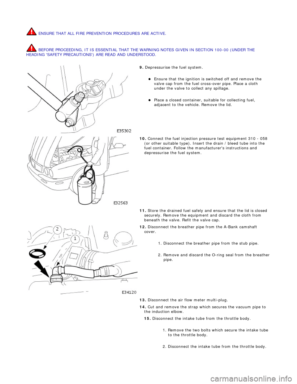
ENSURE THAT ALL FIRE PREVENTION PROCEDURES ARE ACTIVE.
BEFORE PROCEEDING, IT IS ESSENTIAL THAT THE WARNING NOTES GIVEN IN SECTION 100-00 (UNDER THE
HEADING 'SAFETY PRECAUTIONS') ARE READ AND UNDERSTOOD.
9. Depressurise the fuel system.
Ensure that the ignition is switched off and remove the
valve cap from the fuel cross-over pipe. Place a cloth
under the valve to collect any spillage.
Place a closed container, su itable for collecting fuel,
adjacent to the vehicle. Remove the lid.
10. Connect the fuel injection pressure test equipment 310 - 058
(or other suitable type). Insert the drain / bleed tube into the
fuel container. Follow the ma nufacturer's instructions and
depressurise the fuel system.
11. Store the drained fuel safely and ensure that the lid is closed
securely. Remove the equipmen t and discard the cloth from
beneath the valve. Refit the valve cap.
12. Disconnect the breather pipe from the A-Bank camshaft
cover.
1. Disconnect the breather pipe from the stub pipe.
2. Remove and discard the O-ring seal from the breather
pipe.
13. Disconnect the air flow meter multi-plug.
14. Cut and remove the strap which secures the vacuum pipe to
the induction elbow.
15. Disconnect the intake tube from the throttle body.
1. Remove the two bolts which secure the intake tube to the throttle body.
2. Disconnect the intake tube from the throttle body.
Page 907 of 2490

56. Disconnect the fuel feed and return hoses.
1. Disconnect the fuel hoses at the Quick Fit connectors,
using special tool 310 - 044 for the feed hose and
310 - 54 for the return hose.
Disconnect the return hose from the feed hose clip.
Fit blanking plugs to the pipes.
57. Disconnect the pipes from the purge valve.
1. Remove the clip which secu res the part load breather
hose to the purge valve.
2. Disconnect the part load breather hose.
3. Disconnect the vacuum hose from the purge valve and reposition the hose.
58. Disconnect the throttle cable.
1. Secure the cable abutment to the bracket with tape or a ratchet strap, if nece ssary (to save subsequent
adjustment procedure). Remove the bolts which
secure the abutment bracke t to the throttle body.
2. Rotate the butterfly actuator cam and disconnect the cable. Reposition the cable.
59. Disconnect the heater and brake servo hoses.
1. Disconnect the he ater return hose.
2. Release the heater feed hose locking lever and
disconnect the hose.
Page 916 of 2490

3. Conne
ct the brake servo hose.
26. Conne
ct the P.I. harness to the engine management
harness.
1. Reposition the engi ne management harness
connector to the bracket.
2. Fit the nut which secures the engine management harness connector to the mounting bracket.
3. Connect the connectors.
4. Fit the bolt which secures the P.I. harness connector to the engine management harness.
27 . Conne
ct the transmission rotary
switch harness connector.
Re
position and connect the harness.
28 . Con
nect the throttle cable.
1. Fit the bolts which secure the abutment bracket to the throttle body. Tighten to 4-6 Nm.
2. Rotate the butterfly actuator cam and connect the cable. Reposition the cable into the cam.
Re
move any tape or plastic
strap which was fitted when
disconnecting the cable abutment.
29. Connect the pipes to the purge valve.
1. Connect the part load breather hose.
2. Fit the clip which secures the part load breather hose
to the purge valve.
Page 917 of 2490
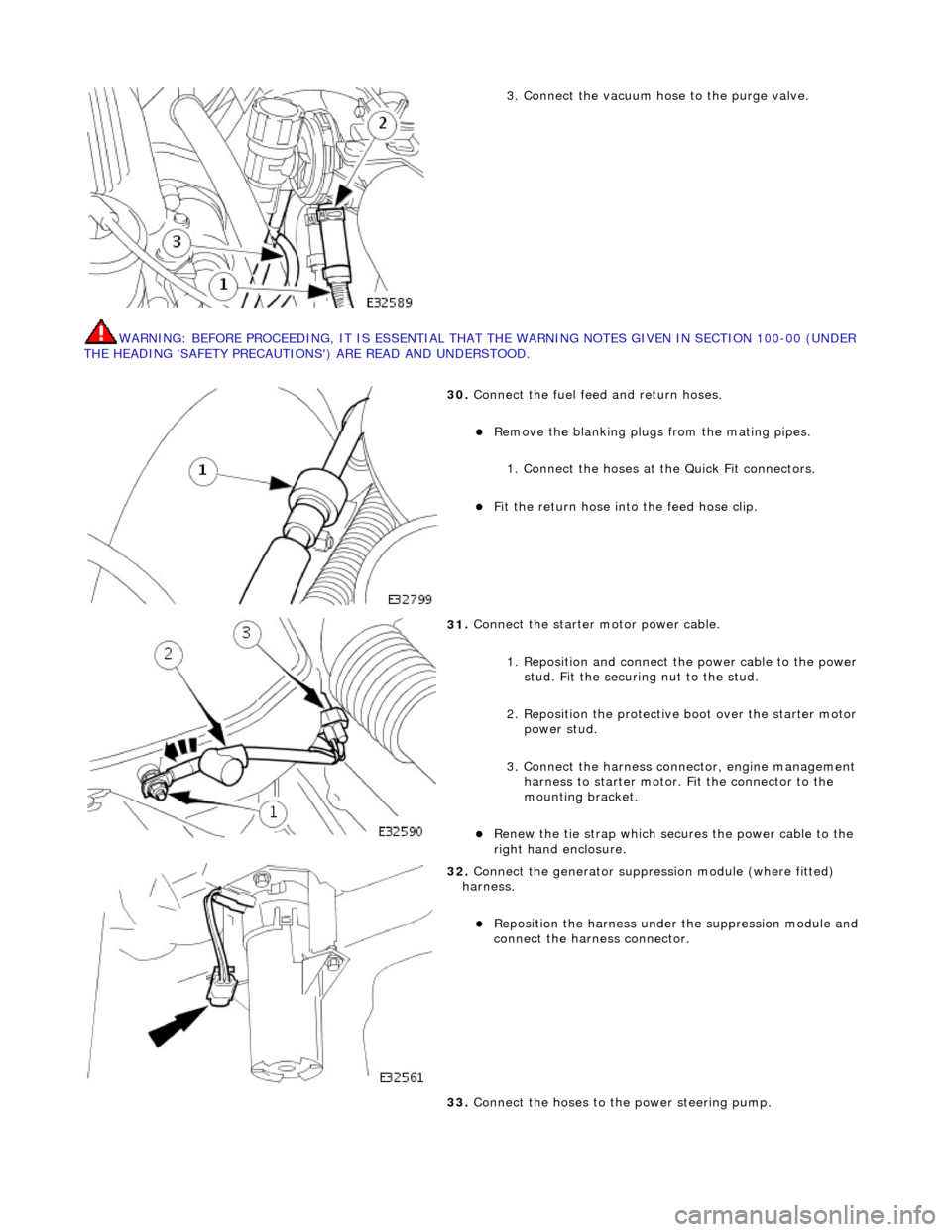
WARNING: B
EFORE PROCEEDING, IT IS ESSENTIAL THAT
THE WARNING NOTES GIVEN IN SECTION 100-00 (UNDER
THE HEADING 'SAFETY PRECAUTION S') ARE READ AND UNDERSTOOD.
3.
Connect the vacuum hose to the purge valve.
30
.
Connect the fuel feed and return hoses.
R
emove the blanking plugs
from the mating pipes.
1. Connect the hoses at the Quick Fit connectors.
F
it the return hose into the feed hose clip.
31
.
Connect the starter motor power cable.
1. Reposition and connect the power cable to the power stud. Fit the securing nut to the stud.
2. Reposition the protective boot over the starter motor power stud.
3. Connect the harness connector, engine management harness to starter motor. Fit the connector to the
mounting bracket.
R
enew the tie strap which secures the power cable to the
right hand enclosure.
32
.
Connect the generator suppressi on module (where fitted)
harness.
Re
position the harn
ess under the suppression module and
connect the harness connector.
33. Connect the hoses to the power steering pump.
Page 925 of 2490
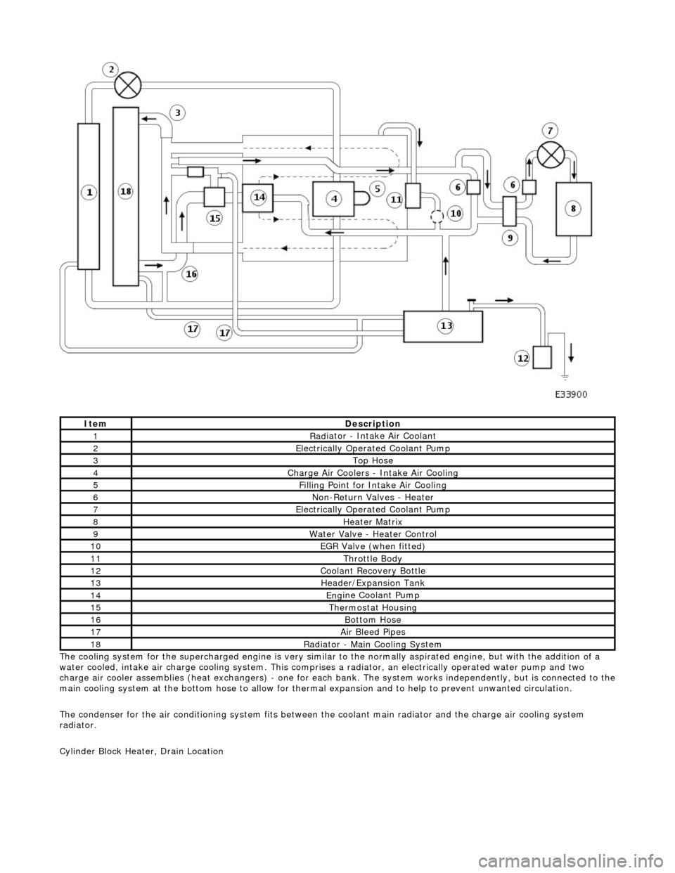
T
he cooling system for the supercharged engine is very similar
to the normally aspirated engine, but with the addition of a
water cooled, intake air charge cooling system. This comprises a radiator, an electrically operated water pump and two
charge air cooler assemblies (heat exchangers) - one for each bank. The system works independently, but is connected to the
main cooling system at the bottom hose to allow for therma l expansion and to help to prevent unwanted circulation.
The condenser for the air conditioning system fits between th e coolant main radiator and the charge air cooling system
radiator.
Cylinder Block Heater, Drain Location
ItemDe
scription
1Rad
iator - Intake Air Coolant
2Ele
ctrically Operated Coolant Pump
3Top Hose
4Charge Air Coo
lers -
Intake Air Cooling
5Fi
lling Point for Intake Air Cooling
6N
on-Return Valves - Heater
7Ele
ctrically Operated Coolant Pump
8Hea
ter Matrix
9Wate
r Valve - Heater Control
10EGR V
alve (when fitted)
11Thr
ottle Body
12Coolan
t Recovery Bottle
13H
eader/Expansion Tank
14Eng
ine Coolant Pump
15The
rmostat Housing
16Bottom
Hose
17Air Bleed
Pipes
18Rad
iator - Main Cooling System
Page 930 of 2490
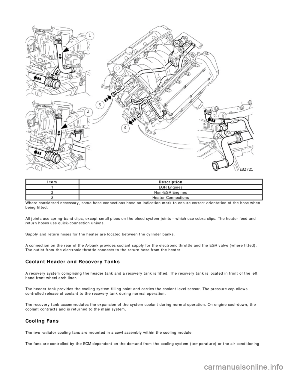
Whe r
e considered necessary, some hose conn
ections have an indication mark to ensure correct orientation of the hose when
being fitted.
All joints use spring-band clips, except small pipes on the bleed system joints - which use cobra clips. The heater feed and
return hoses use quick-connection unions.
Supply and return hoses for the heater are located between the cylinder banks.
A connection on the rear of the A-bank provides coolant supply for the electronic throttle and the EGR valve (where fitted).
The outlet from the electronic throttle connects to the return hose from the heater.
Cool
ant Header and Recovery Tanks
A recovery system comp
rising the header tank
and a recovery tank is fitted. The recove ry tank is located in front of the left
hand front wheel arch liner.
The header tank provides the cooling system filling point and carries the coolant level sensor. The pressure cap allows
controlled release of coolant to the re covery tank during normal operation.
The recovery tank accommodates the expansion of the system coolant during normal operation. On engine cool-down, the
coolant contracts and is returned to the main system.
Coo lin
g Fans
The two
rad
iator cooling fans are mounted in
a cowl assembly within the cooling module.
The fans are controlled by the ECM dependent on the demand fr om the cooling system (temperature) or the air conditioning
ItemDescrip
tion
1EGR
E
ngines
2Non
-
EGR Engines
3Hea
ter Connections
Page 960 of 2490
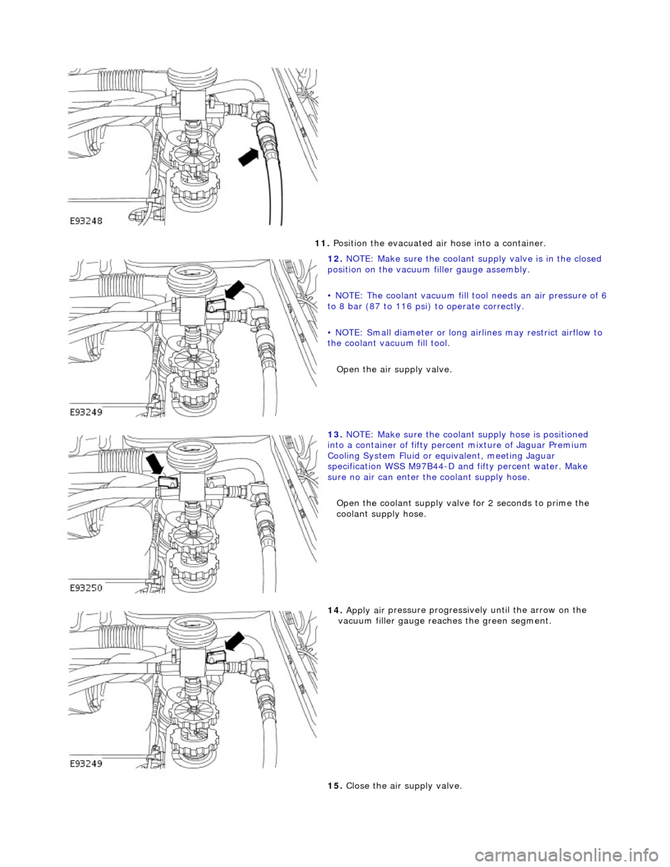
11. P
osition the evacuated air hose into a container.
12 . N
OTE: Make sure the coolant su
pply valve is in the closed
position on the vacuum filler gauge assembly.
• NOTE: The coolant vacuum fill t ool needs an air pressure of 6
to 8 bar (87 to 116 psi) to operate correctly.
• NOTE: Small diameter or long airlines may restrict airflow to
the coolant vacuum fill tool. Open the air supply valve.
13 .
NOTE
: Make sure the coolant supply hose is positioned
into a container of fifty perc ent mixture of Jaguar Premium
Cooling System Fluid or eq uivalent, meeting Jaguar
specification WSS M97B44-D an d fifty percent water. Make
sure no air can enter the coolant supply hose.
Open the coolant supply valve for 2 seconds to prime the
coolant supply hose.
14 . Apply air
pressure
progressively until the arrow on the
vacuum filler gauge reac hes the green segment.
15. Close the air supply valve.
Page 961 of 2490
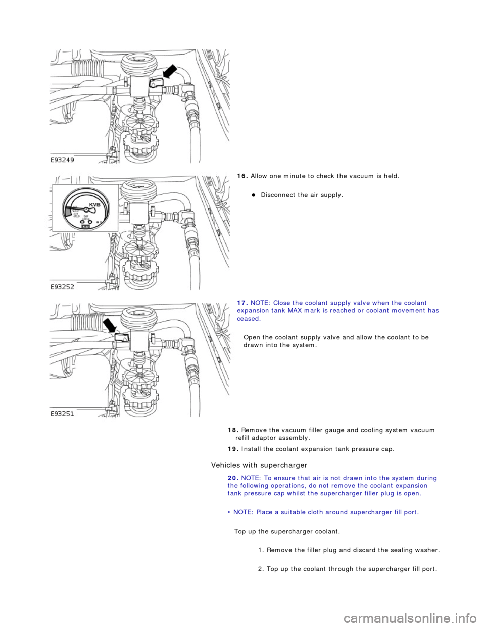
Vehic
les with supercharger
16
.
Allow one minute to check the vacuum is held.
Di
sconnect the air supply.
17
.
NOTE: Close the coolant supply valve when the coolant
expansion tank MAX mark is reached or coolant movement has
ceased.
Open the coolant supply valve and allow the coolant to be
drawn into the system.
18. Remove the vacuum filler gaug e and cooling system vacuum
refill adaptor assembly.
19. Install the coolant expansion tank pressure cap.
20. NOTE: To ensure that air is not drawn into the system during
the following operations, do not remove the coolant expansion
tank pressure cap whilst the supe rcharger filler plug is open.
• NOTE: Place a suitable cloth ar ound supercharger fill port.
Top up the superc harger coolant.
1. Remove the filler plug an d discard the sealing washer.
2. Top up the coolant through the supercharger fill port.
Page 967 of 2490

I
nstallation
8.
Remove an
d discard the sealing
rings from the outlet pipe
grooves.
1. Installation is th e reverse of the re moval procedure.
Use new
sealing rings on th
e coolant outlet pipe and
thermostat housing.
The t
hermostat ball valve must
locate in the recess in the
cover.
2. Tighten the coolant outlet pipe bolts to 8-12 Nm. If replacing
the coolant temperature sensor, tighten to 15-19 Nm.
3. Refill the cooling system as de scribed in General Procedures.