valve JAGUAR X308 1998 2.G Owners Manual
[x] Cancel search | Manufacturer: JAGUAR, Model Year: 1998, Model line: X308, Model: JAGUAR X308 1998 2.GPages: 2490, PDF Size: 69.81 MB
Page 871 of 2490

throttle body.
11. Refit the purge valve. Refer to Operation 17.45.01.
12. Reconnect the air flow meter multi-plug.
13. Refit the left hand engine cover.
14. Remove the paintwork protection sheets and close the engine
compartment.
Page 872 of 2490

Engine - Valve Cover Gasket RH
In-vehicle Repair
Removal
1. Open the engine compartment and fit paintwork protection
sheets.
2. Carefully remove the right hand engine cover, taking care not
to damage the plastic fixi ngs or the rubber inserts.
3. Remove the on-plug ignition coils from the 'A' bank. Refer to
Operation 18.20.41.
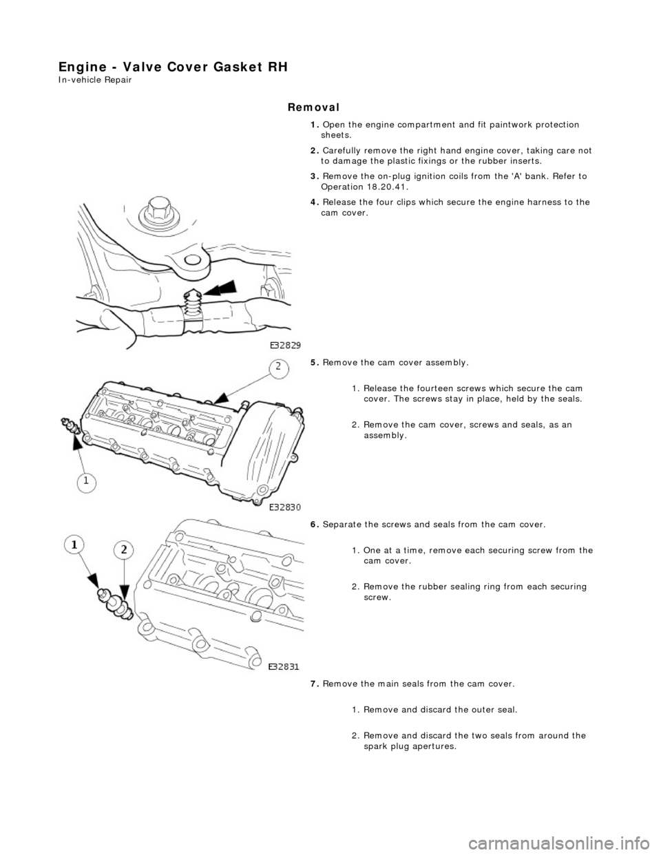
4. Release the four clips which secure the engine harness to the
cam cover.
5. Remove the cam cover assembly.
1. Release the fourteen sc rews which secure the cam
cover. The screws stay in place, held by the seals.
2. Remove the cam cover, screws and seals, as an
assembly.
6. Separate the screws and se als from the cam cover.
1. One at a time, remove ea ch securing screw from the
cam cover.
2. Remove the rubber sealin g ring from each securing
screw.
7. Remove the main seals from the cam cover.
1. Remove and discard the outer seal.
2. Remove and discard the two seals from around the spark plug apertures.
Page 875 of 2490

Engine - Valve Springs LH
In-vehicle Repair
Removal
Special Tool(s)
Valve spring compressor
303-252 1. Open the engine compartment and fit paintwork protection
sheets.
2. Set the engine compartment cover to the service access
position.
3. Disconnect the batt ery ground cable.
Remove the battery cover.
4. Remove the Timing Co ver. Refer to Operation 12.65.01 in this
Section. This operation includes draining the coolant from the
radiator and removing the cam covers.
5. Remove the Inlet Manifold. Refer to Operation 30.15.01 in this
Section. This operation includes depressurising the fuel system
and removing the throttle housing.
6. Remove the Cylinder Head an d Gasket. Refer to Operation
12.29.02 in this Section.
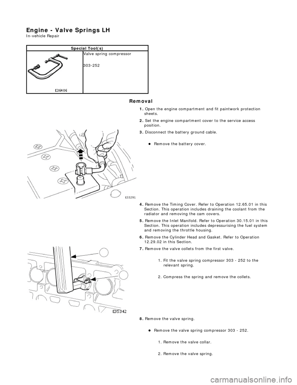
7. Remove the valve collets from the first valve.
1. Fit the valve spring compressor 303 - 252 to the relevant spring.
2. Compress the spring and remove the collets.
8. Remove the valve spring.
Remove the valve spring compressor 303 - 252.
1. Remove the valve collar.
2. Remove the valve spring.
Page 876 of 2490

Installation
9. Repeat the instructions for each valve spring to be removed.
10. Clean all relevant components.
1. Fit the valve spring.
1. Fit the valve spring.
2. Locate the valve collar onto the spring.
2. Refit the valve collets to the first valve.
1. Fit the valve spring compressor 303 - 252 to the relevant spring.
2. Compress the spring and fit the collets.
Remove the valve spring compressor and check that the
collets are correctly seated.
3. Repeat the instructions for each valve spring to be fitted.
4. Refit the Cylinder Head and Gasket. Refer to Operation
12.29.03 in this Section.
5. Refit the Inlet Manifold. Refer to Operation 30.15.01 in this
Section. This operation includes refitting the throttle housing.
6. Refit the Timing Cover. Refer to Operation 12.65.01 in this
Section. This operation includes refitting the cam covers and
refilling the coolant system.
7. Move the engine compartment co ver from the service position
and connect the gas struts.
8. Remove the paint protection sheets and close the cover.
9. Connect the battery and fit the battery cover.
Refer to the Battery Reconnection Procedure 86.15.15.
Page 877 of 2490

Engine - Valve Springs RH
In-vehicle Repair
Removal
Special Tool(s)
Valve spring compressor
303-252 1. Open the engine compartment and fit paintwork protection
sheets.
2. Set the engine compartment cover to the service access
position.
3. Disconnect the batt ery ground cable.
Remove the battery cover.
4. Remove the Timing Co ver. Refer to Operation 12.65.01 in this
Section. This operation includes draining the coolant from the
radiator and removing the cam covers.
5. Remove the Inlet Manifold. Refer to Operation 30.15.01 in this
Section. This operation includes depressurising the fuel system
and removing the throttle housing.
6. Remove the Cylinder Head an d Gasket. Refer to Operation
12.29.03 in this Section.
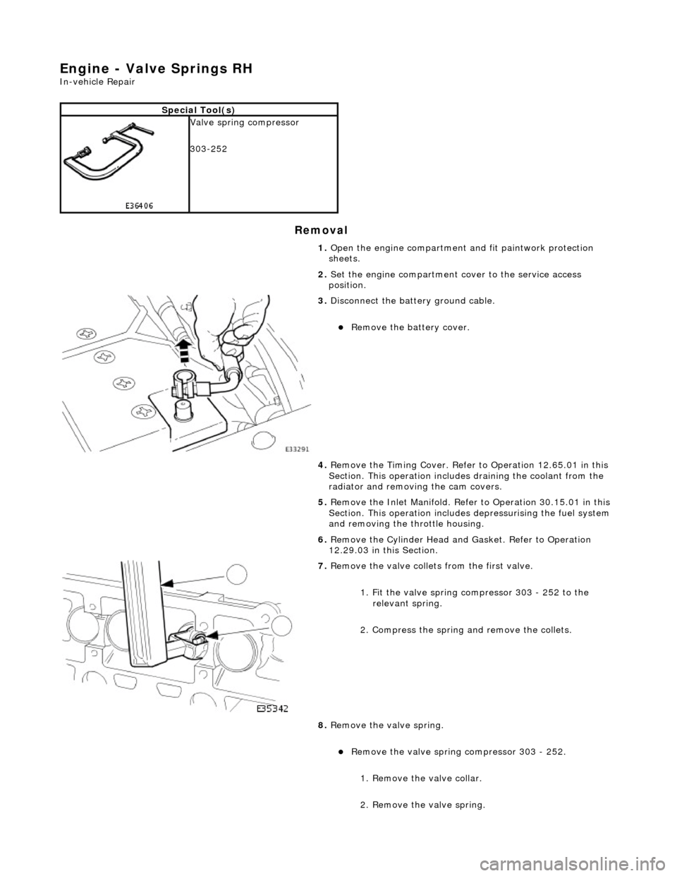
7. Remove the valve collets from the first valve.
1. Fit the valve spring compressor 303 - 252 to the relevant spring.
2. Compress the spring and remove the collets.
8. Remove the valve spring.
Remove the valve spring compressor 303 - 252.
1. Remove the valve collar.
2. Remove the valve spring.
Page 878 of 2490

Installation
9. Repeat the instructions for each valve spring to be removed.
10. Clean all relevant components.
1. Fit the valve spring.
1. Fit the valve spring.
2. Locate the valve collar onto the spring.
2. Refit the valve collets to the first valve.
1. Fit the valve spring compressor 303 - 252 to the relevant spring.
2. Compress the spring and fit the collets.
Remove the valve spring compressor and check that the
collets are correctly seated.
3. Repeat the instructions for each valve spring to be fitted.
4. Refit the Cylinder Head and Gasket. Refer to Operation
12.29.03 in this Section.
5. Refit the Inlet Manifold. Refer to Operation 30.15.01 in this
Section. This operation includes refitting the throttle housing.
6. Refit the Timing Cover. Refer to Operation 12.65.01 in this
Section. This operation includes refitting the cam covers and
refilling the coolant system.
7. Move the engine compartment co ver from the service position
and connect the gas struts.
8. Remove the paint protection sheets and close the cover.
9. Connect the battery and fit the battery cover.
Refer to the Battery Reconnection Procedure 86.15.15.
Page 879 of 2490

Engine - Variable Camshaft Timing Oil Control Unit LH
In-vehicle Repair
Removal
Special Tool(s)
Camshaft setting
303-530
Timing chain tensioning
303-532
Wedges, primary chain
303-533
Crankshaft setting
303-531
1. Open the engine compartment and fit paintwork protection
sheets.
2. Set the engine compartment cover to the service access
position.
3. Disconnect the batt ery ground cable.
Remove the battery cover.
4. Remove the Timing Co ver. Refer to Operation 12.65.01 in this
Section.
5. Remove the Variable Valve Ti ming Bush Carrier Assembly.
Refer to Operation 12.65.52 in this Section
6. Raise the vehicle on a ramp.
7. Remove the crankshaft position sensor.
Page 881 of 2490

15. Loosen the bolt which secures the VVT unit.
Do not tamper with the three bolts which secure the VVT
mechanism to the sprockets. It is sealed at the factory to
the correct valve timing specif ication for the engine and is
supplied only as a complete unit.
16. Remove the primary chain tens ioner. Refer to operation
12.65.55, in this Section.
17. Remove the primary ch ain tensioner blade.
1. Remove the pivot bolt which secures the tensioner blade.
2. Remove the tensioner blade.
18. Reposition the VVT unit along the cam journal to allow the
chain to clear the head casting.
Disconnect the primary chain from the VVT unit and
reposition it against the crankshaft sprocket.
19. Remove the VVT unit.
1. Remove the securing bolt from the VVT unit and the exhaust cam sprocket.
2. Remove the VVT unit, exhaust sprocket and secondary chain as an asse mbly (release the chain
from the tensioner which is still secured to the
cylinder head).
Remove the secondary chain from the VVT unit and the
sprocket.
Page 882 of 2490

Installation
20. Clean and inspect all relevant components.
1. Push the tensioner piston (secon dary chain) into the body to
provide clearance for fitting.
1. Insert a thin rigid wire th rough the hole in the end of
the tensioner piston to displace the ball from the non-
return valve seat.
2. With the wire in position, press the piston fully into the tensioner body.
Remove the wire.
2. Fit the VVT unit to the engine.
Assemble the VVT unit, the exhaust camshaft sprocket
and the secondary chain, in pr eparation for fitting to the
engine.
1. Fit the above assembly to the camshafts with the chain correctly positioned over the tensioner; VVT
unit to the inlet and the sprocket to the exhaust.
2. Fit, but do not tighten, each bolt which secures the VVT unit and the exhaust sprocket to the camshafts.
Allow the VVT unit sufficien t space to fit the primary
chain, in a la ter operation.
3. Fit the chain tensioning tool 303 - 532 to the exhaust camshaft
sprocket.
Reposition the sprocket (and the VVT unit) for the most
advantageous position for use of the tool.
Remove the tool.
4. Refit the primary timing chain.
1. Lift the primary chain an d position it over the VVT
unit sprocket (the VVT unit mu st be pulled forward to
clear the cylinder head casting). There must be no
slack on the drive side of the primary chain and the
VVT unit must not be rotated on the camshaft.
2. Slide the VVT unit fully on to the camshaft.
5. Fit the primary chain tensioner blade.
1. Position the tensioner blade to the cylinder block.
Page 885 of 2490

Engine - Variable Camshaft Timing Oil Control Unit RH
In-vehicle Repair
Removal
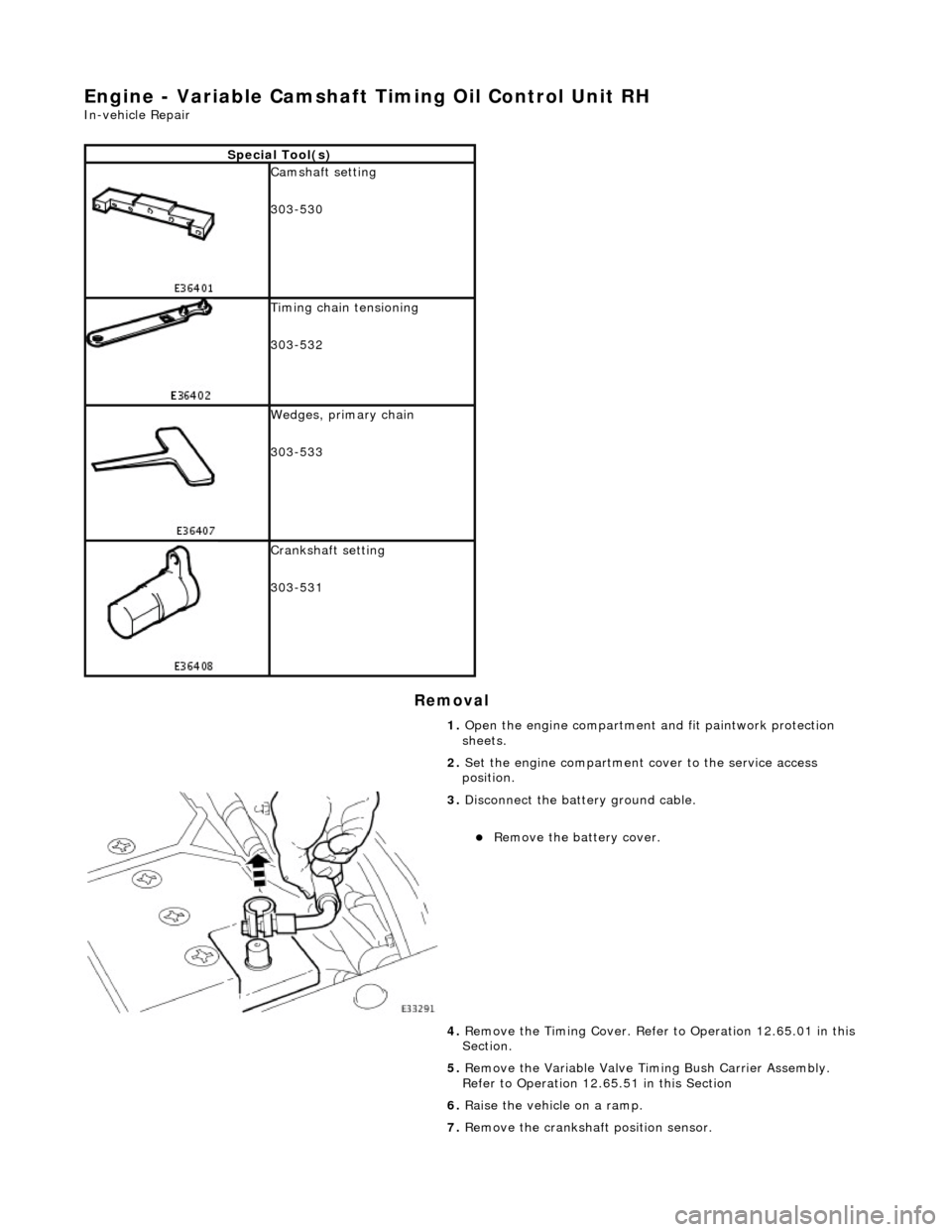
Special Tool(s)
Camshaft setting
303-530
Timing chain tensioning
303-532
Wedges, primary chain
303-533
Crankshaft setting
303-531
1. Open the engine compartment and fit paintwork protection
sheets.
2. Set the engine compartment cover to the service access
position.
3. Disconnect the batt ery ground cable.
Remove the battery cover.
4. Remove the Timing Co ver. Refer to Operation 12.65.01 in this
Section.
5. Remove the Variable Valve Ti ming Bush Carrier Assembly.
Refer to Operation 12.65.51 in this Section
6. Raise the vehicle on a ramp.
7. Remove the crankshaft position sensor.