valve JAGUAR X308 1998 2.G Manual Online
[x] Cancel search | Manufacturer: JAGUAR, Model Year: 1998, Model line: X308, Model: JAGUAR X308 1998 2.GPages: 2490, PDF Size: 69.81 MB
Page 842 of 2490
Installation
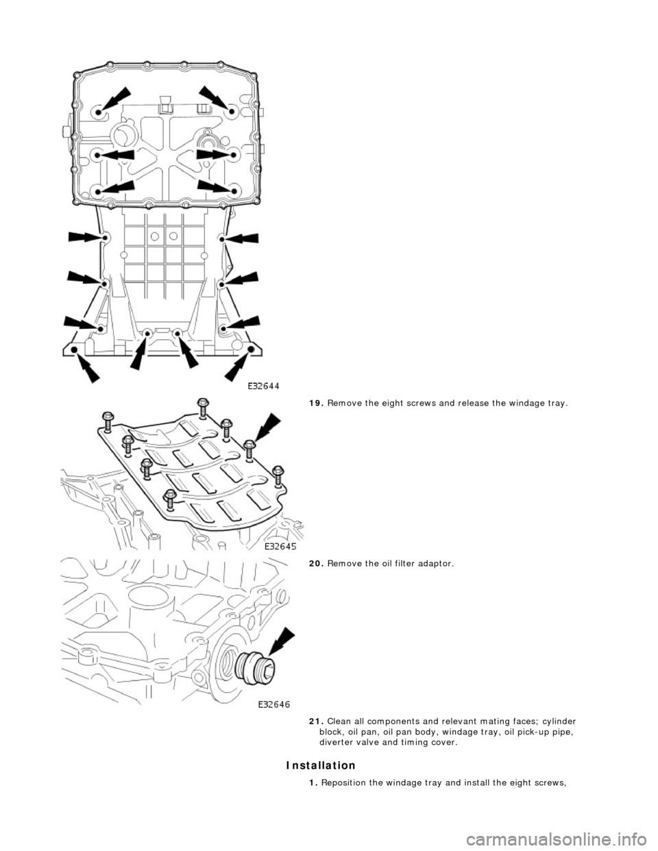
19. Remove the eight screws an d release the windage tray.
20. Remove the oil filter adaptor.
21. Clean all components and releva nt mating faces; cylinder
block, oil pan, oil pan body, windage tray, oil pick-up pipe,
diverter valve and timing cover.
1. Reposition the windage tray and install the eight screws,
Page 843 of 2490
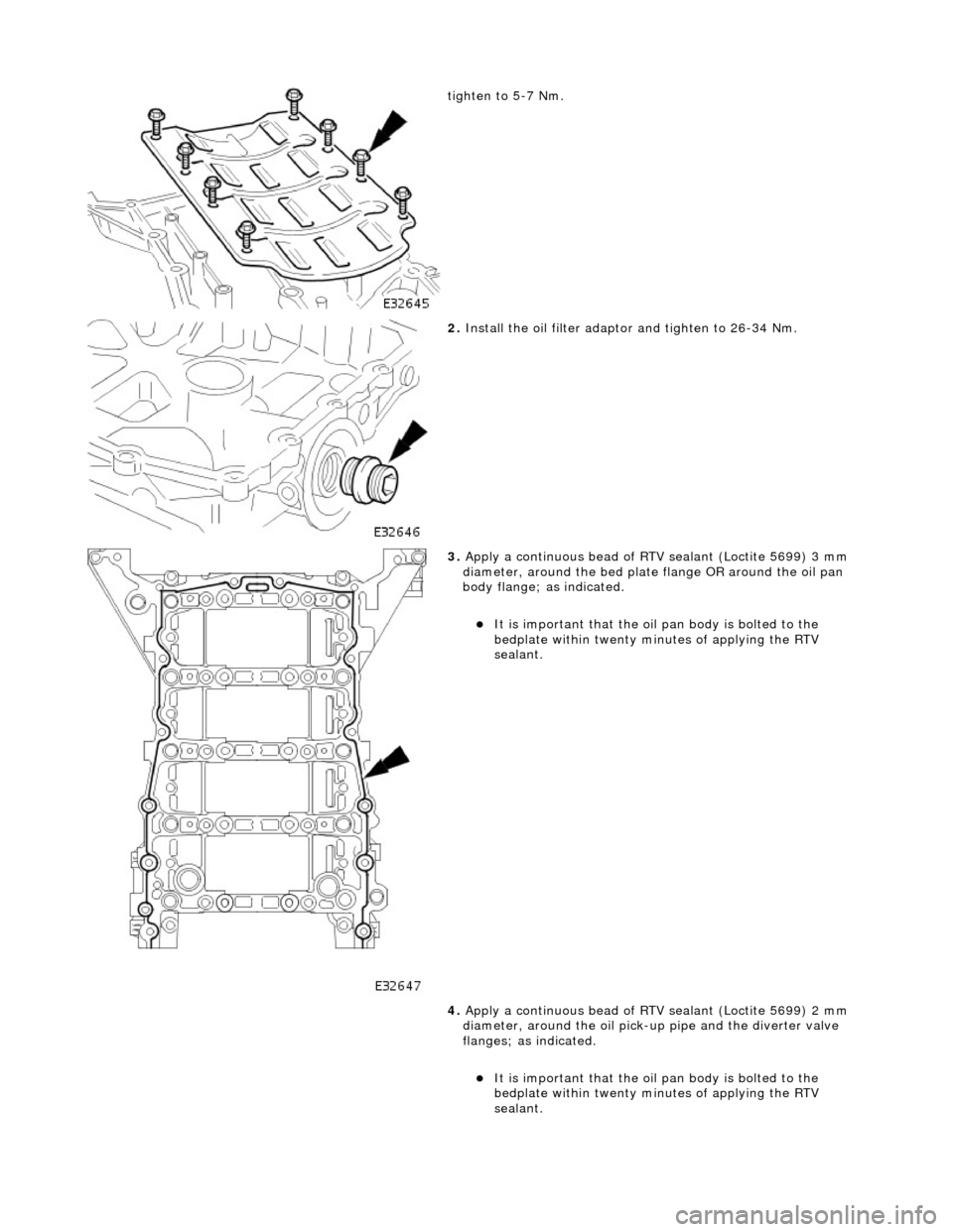
tighten to 5-7 Nm.
2. Install the oil filter adapto r and tighten to 26-34 Nm.
3. Apply a continuous bead of RTV sealant (Loctite 5699) 3 mm
diameter, around the bed plate flange OR around the oil pan
body flange; as indicated.
It is important that the oil pan body is bolted to the
bedplate within twenty minutes of applying the RTV
sealant.
4. Apply a continuous bead of RTV sealant (Loctite 5699) 2 mm
diameter, around the oil pick-u p pipe and the diverter valve
flanges; as indicated.
It is important that the oil pan body is bolted to the
bedplate within twenty minutes of applying the RTV
sealant.
Page 851 of 2490
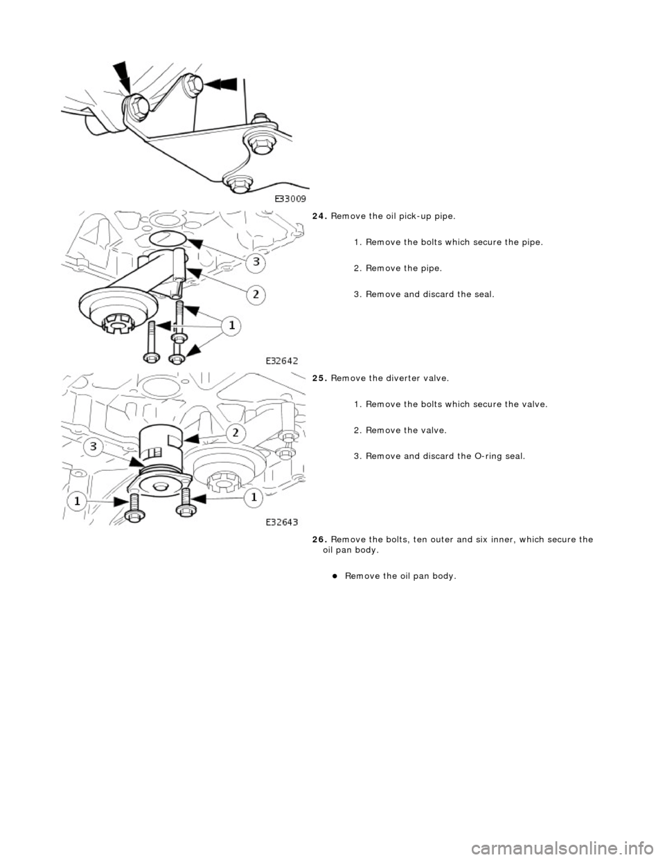
24. Remove the oil pick-up pipe.
1. Remove the bolts which secure the pipe.
2. Remove the pipe.
3. Remove and discard the seal.
25. Remove the diverter valve.
1. Remove the bolts which secure the valve.
2. Remove the valve.
3. Remove and discard the O-ring seal.
26. Remove the bolts, ten outer an d six inner, which secure the
oil pan body.
Remove the oil pan body.
Page 852 of 2490
Installation
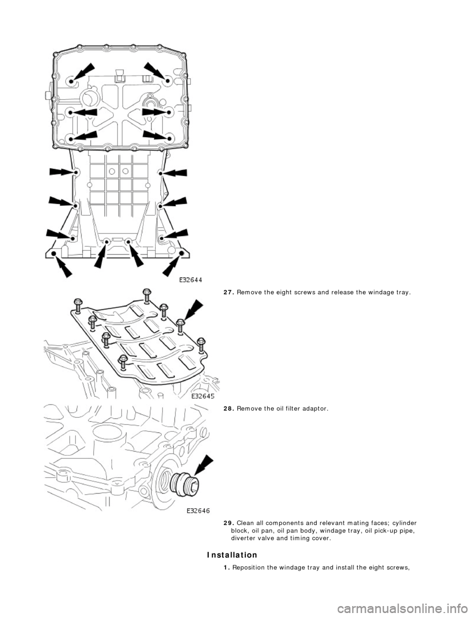
27. Remove the eight screws an d release the windage tray.
28. Remove the oil filter adaptor.
29. Clean all components and releva nt mating faces; cylinder
block, oil pan, oil pan body, windage tray, oil pick-up pipe,
diverter valve and timing cover.
1. Reposition the windage tray and install the eight screws,
Page 853 of 2490
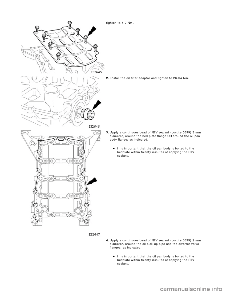
tighten to 5-7 Nm.
2. Install the oil filter adapto r and tighten to 26-34 Nm.
3. Apply a continuous bead of RTV sealant (Loctite 5699) 3 mm
diameter, around the bed plate flange OR around the oil pan
body flange; as indicated.
It is important that the oil pan body is bolted to the
bedplate within twenty minutes of applying the RTV
sealant.
4. Apply a continuous bead of RTV sealant (Loctite 5699) 2 mm
diameter, around the oil pick-u p pipe and the diverter valve
flanges; as indicated.
It is important that the oil pan body is bolted to the
bedplate within twenty minutes of applying the RTV
sealant.
Page 854 of 2490

5. Position and align the oil pan body to the bedplate.
Install the sixteen bolts and tighten to 20-22 Nm in the
sequence indicated.
6. Install the oil diverter valve.
1. Install a new O-ring seal to the diverter valve.
2. Lubricate the O-ring seal with clean engine oil and install the valve into the oil pan body.
Page 859 of 2490
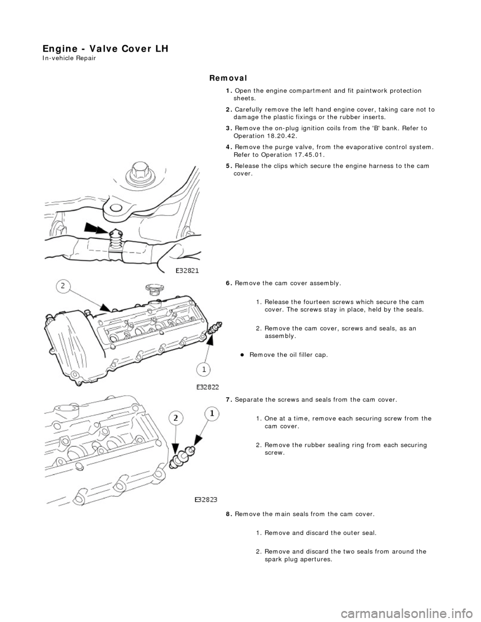
Engine - Valve Cover LH
In-vehicle Repair
Removal
1. Open the engine compartment and fit paintwork protection
sheets.
2. Carefully remove the le ft hand engine cover, taking care not to
damage the plasti c fixings or the rubber inserts.
3. Remove the on-plug ignition coils from the 'B' bank. Refer to
Operation 18.20.42.
4. Remove the purge valve, from th e evaporative control system.
Refer to Operation 17.45.01.
5. Release the clips which secure the engine harness to the cam
cover.
6. Remove the cam cover assembly.
1. Release the fourteen sc rews which secure the cam
cover. The screws stay in place, held by the seals.
2. Remove the cam cover, screws and seals, as an
assembly.
Remove the oil filler cap.
7. Separate the screws and se als from the cam cover.
1. One at a time, remove ea ch securing screw from the
cam cover.
2. Remove the rubber sealin g ring from each securing
screw.
8. Remove the main seals from the cam cover.
1. Remove and discard the outer seal.
2. Remove and discard the two seals from around the spark plug apertures.
Page 861 of 2490

securing screw.
5. Tighten the securing screws to 9 - 11 Nm. Tighten in the
sequence indicated.
6. Fit the oil filler cap.
7. Reposition the clips which secure the engine harness to the
cam cover.
8. Refit the on-plug ignition coils and the coil cover. Refer to
Operation 18.20.42.
9. Refit the purge valve. Refer to Operation 17.45.01.
10. Reconnect the air flow meter multi-plug.
11. Refit the left hand engine cover.
12. Remove the paintwork protection sheets and close the engine
compartment.
Page 862 of 2490

Engine - Valve Cover RH
In-vehicle Repair
Removal
1. Open the engine compartment and fit paintwork protection
sheets.
2. Disconnect the intake tube from the throttle body.
1. Remove the two bolts which secure the intake tube to the throttle body.
2. Disconnect the intake tube from the throttle body.
3. Disconnect the air cleaner cover.
Release the five clips which se cure the air cleaner cover.
4. Disconnect the air fl ow meter multi-plug.
5. Remove the intake tube / air flow meter / air cleaner cover
assembly.
1. Remove the intake tube / air flow meter / air cleaner
cover assembly.
2. Remove and discard the ru bber seal; air intake tube
to throttle body.
6. Carefully remove the right hand engine cover, taking care not
to damage the plastic fixi ngs or the rubber inserts.
7. Remove the on-plug ignition coils from the 'A' bank. Refer to
Operation 18.20.41.
8. Release the clips which secure the engine harness to the cam
cover.
Page 867 of 2490
Engine - Valve Cover Gasket LH
In-vehicle Repair
Removal
1. Open the engine compartment and fit paintwork protection
sheets.
2. Carefully remove the le ft hand engine cover, taking care not to
damage the plasti c fixings or the rubber inserts.
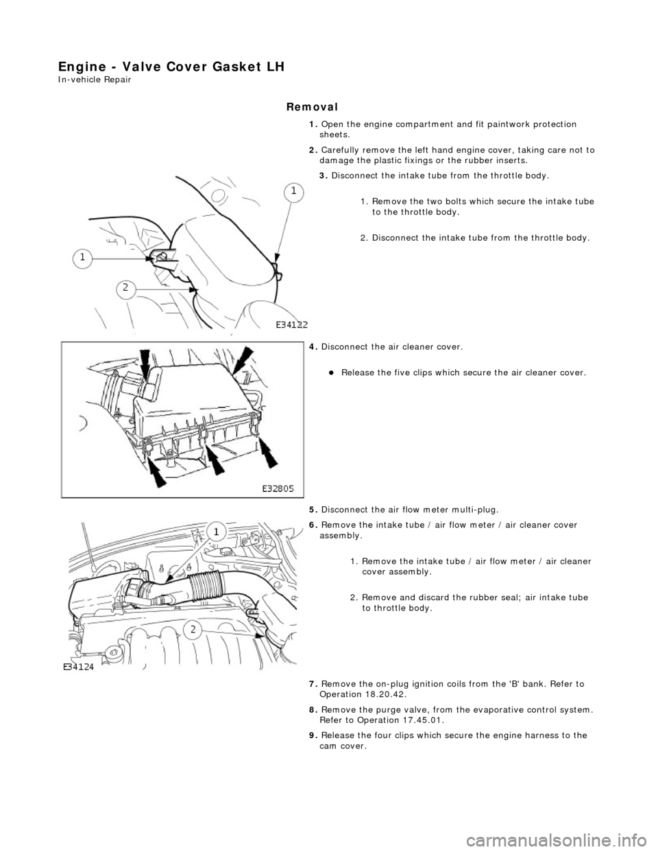
3. Disconnect the intake tube from the throttle body.
1. Remove the two bolts which secure the intake tube to the throttle body.
2. Disconnect the intake tube from the throttle body.
4. Disconnect the air cleaner cover.
Release the five clips which se cure the air cleaner cover.
5. Disconnect the air fl ow meter multi-plug.
6. Remove the intake tube / air flow meter / air cleaner cover
assembly.
1. Remove the intake tube / air flow meter / air cleaner
cover assembly.
2. Remove and discard the ru bber seal; air intake tube
to throttle body.
7. Remove the on-plug ignition coils from the 'B' bank. Refer to
Operation 18.20.42.
8. Remove the purge valve, from th e evaporative control system.
Refer to Operation 17.45.01.
9. Release the four clips which secure the engine harness to the
cam cover.