Seat JAGUAR X308 1998 2.G Workshop Manual
[x] Cancel search | Manufacturer: JAGUAR, Model Year: 1998, Model line: X308, Model: JAGUAR X308 1998 2.GPages: 2490, PDF Size: 69.81 MB
Page 1764 of 2490
Clima
te Control System - General Inform
ation - Manifold Gauge Set Connection
Ge
neral Procedures
Mani
fol
d.
Low Side Pressure Gauge.
High Side Pressure Gauge.
1.
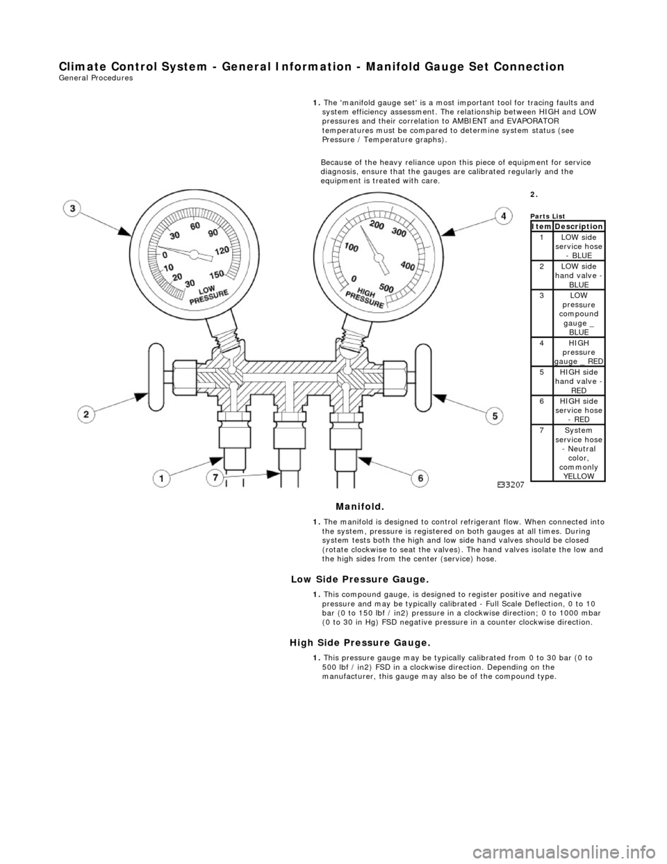
The 'ma
nifold gauge set' is a most important tool for tracing faults and
system efficiency assessment. The relationship between HIGH and LOW
pressures and their correlation to AMBIENT and EVAPORATOR
temperatures must be compared to determine system status (see
Pressure / Temperature graphs).
Because of the heavy reliance upon this piece of equipment for service
diagnosis, ensure that the gauges are calibrated regularly and the
equipment is treated with care.
2.
Parts
List
ItemDescri
ption1LOW side
serv
ice hose
- BLUE
2LOW side
ha
nd valve -
BL
UE3LOW
pres
sure
compound
gauge _ BLUE
4HI GH
pressure
gauge _ RED
5HI GH
side
hand valve -
RED6HI GH
side
service hose
- RED
7Sys t
em
service hose
- Neutral color,
commonly YELLOW
1. The manifold is designed to control refrigerant flow. When connected into
the system, pressure is registered on both gauges at all times. During
system tests both the high and low side hand valves should be closed
(rotate clockwise to seat the valves). The hand valves isolate the low and
the high sides from the center (service) hose.
1. This compound gauge, is designed to register positive and negative
pressure and may be typically calibrate d - Full Scale Deflection, 0 to 10
bar (0 to 150 lbf / in2) pressure in a clockwise direction; 0 to 1000 mbar
(0 to 30 in Hg) FSD negative pressu re in a counter clockwise direction.
1. This pressure gauge may be typically calibrated from 0 to 30 bar (0 to
500 lbf / in2) FSD in a clockwise direction. Depending on the
manufacturer, this gauge may also be of the compound type.
Page 1777 of 2490
Air Distribution and Filtering - Center Registers
Removal and Installation
Removal
Installation
1.
Remove battery cover and disconnect ground cable from battery
terminal. Refer to 86.15.19.
2. Remove passenger airbag deployment door for access. Refer to
Section 501-20.
3. Remove major gauge module veneer panel for access. Refer to
76.47.24.
4. Carefully withdraw fascia centre veneer panel.
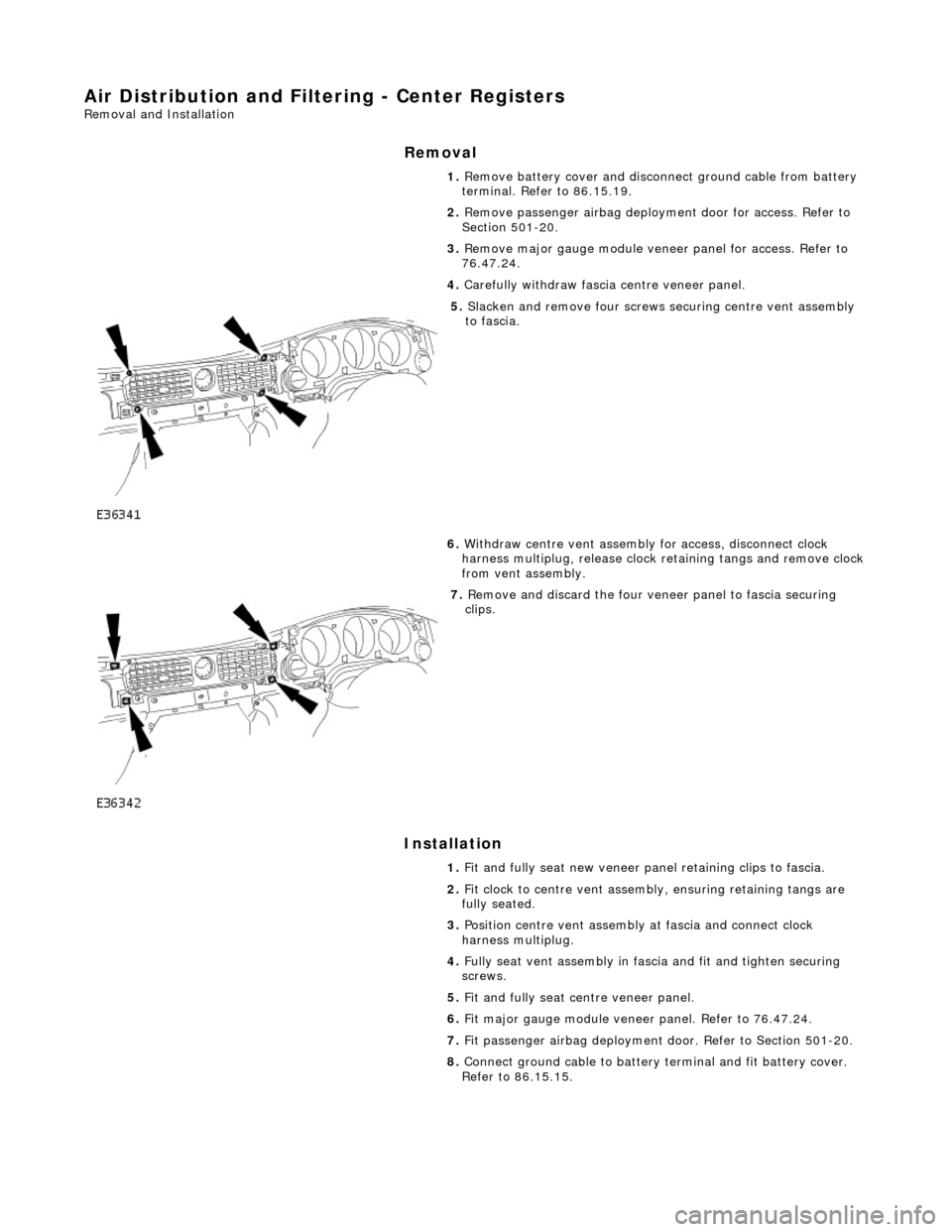
5. Slacken and remove four screws securing centre vent assembly
to fascia.
6. Withdraw centre vent assembly for access, disconnect clock
harness multiplug, release clock retaining tangs and remove clock
from vent assembly.
7. Remove and discard the four veneer panel to fascia securing
clips.
1. Fit and fully seat new veneer panel retaining clips to fascia.
2. Fit clock to centre vent assemb ly, ensuring retaining tangs are
fully seated.
3. Position centre vent assembly at fascia and connect clock
harness multiplug.
4. Fully seat vent assembly in fascia and fit and tighten securing
screws.
5. Fit and fully seat centre veneer panel.
6. Fit major gauge module veneer panel. Refer to 76.47.24.
7. Fit passenger airbag deployment door. Refer to Section 501-20.
8. Connect ground cable to battery terminal and fit battery cover.
Refer to 86.15.15.
Page 1797 of 2490
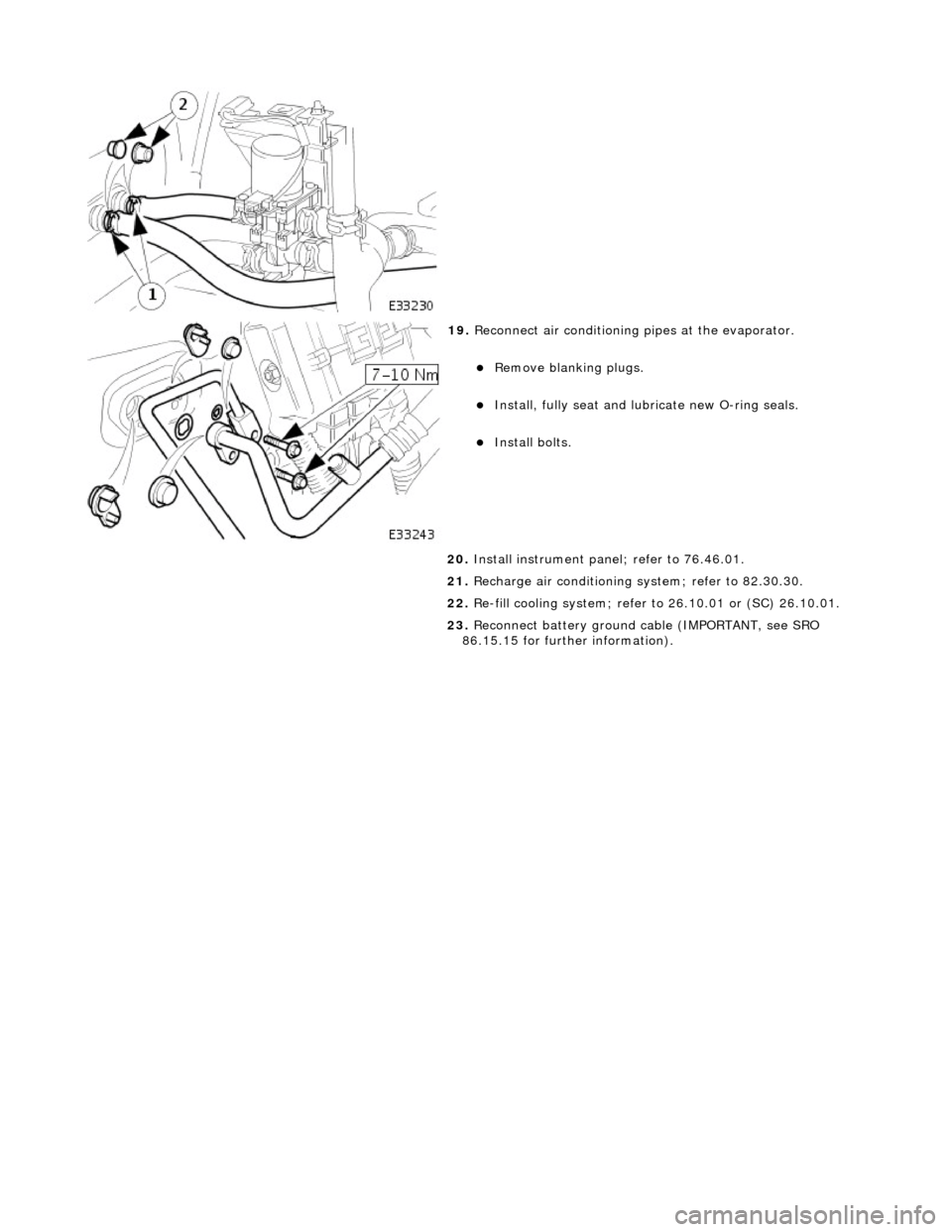
19. Reconnect air conditioning pipes at the evaporator.
Remove blanking plugs.
Install, fully seat and lubr icate new O-ring seals.
Install bolts.
20. Install instrument pane l; refer to 76.46.01.
21. Recharge air conditioning system; refer to 82.30.30.
22. Re-fill cooling system; refer to 26.10.01 or (SC) 26.10.01.
23. Reconnect battery ground cable (IMPORTANT, see SRO
86.15.15 for further information).
Page 1803 of 2490
Refrigeration Cycle
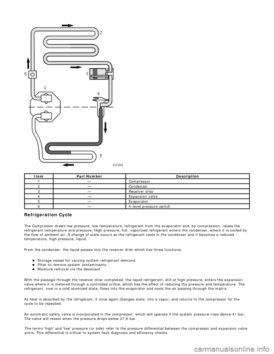
The Compressor draws low pressure, lo
w te
mperature, refrigerant from the evaporat or and, by compression, raises the
refrigerant temperature and pressure. High pressure, hot, vaporized refr igerant enters the condenser, where it is cooled by
the flow of ambient air. A change of state occurs as the refrigerant cools in the condense r and it becomes a reduced
temperature, high pressure, liquid.
From the condenser, the liquid passes into the receiver drier which has three functions:
Storage vessel
for varying sy
stem refrigerant demand.
F
ilter to remove sy
stem contaminants.
Mo
isture removal via the dessicant.
With the passage through the receiver drie r completed, the liquid refrigerant, still at high pressure, enters the expansion
valve where it is metered through a contro lled orifice, which has the effect of reducing the pres sure and temperature. The
refrigerant, now in a cold atomized st ate, flows into the evaporator and cools the air passing through the matrix.
As heat is absorbed by the refrigerant, it once again changes state, into a vapor, and returns to the compressor for the
cycle to be repeated.
An automatic safety valve is incorporated in the compressor, which will operate if the system pressure rises above 41 bar.
The valve will reseat when the pressure drops below 27,6 bar.
It
em
Par
t Number
De
scription
1—Compre
ssor
2—Conden
ser
3—Re
ceiver drier
4—Expans
ion valve
5—Evaporator
6—4
-level pressure switch
The terms 'high' and 'low'
pressure (or si
de) refer to the pres sure differential betw een the compressor and expansion valve
ports. This differential is critical to sy stem fault diagnosis and efficiency checks.
Page 1846 of 2490
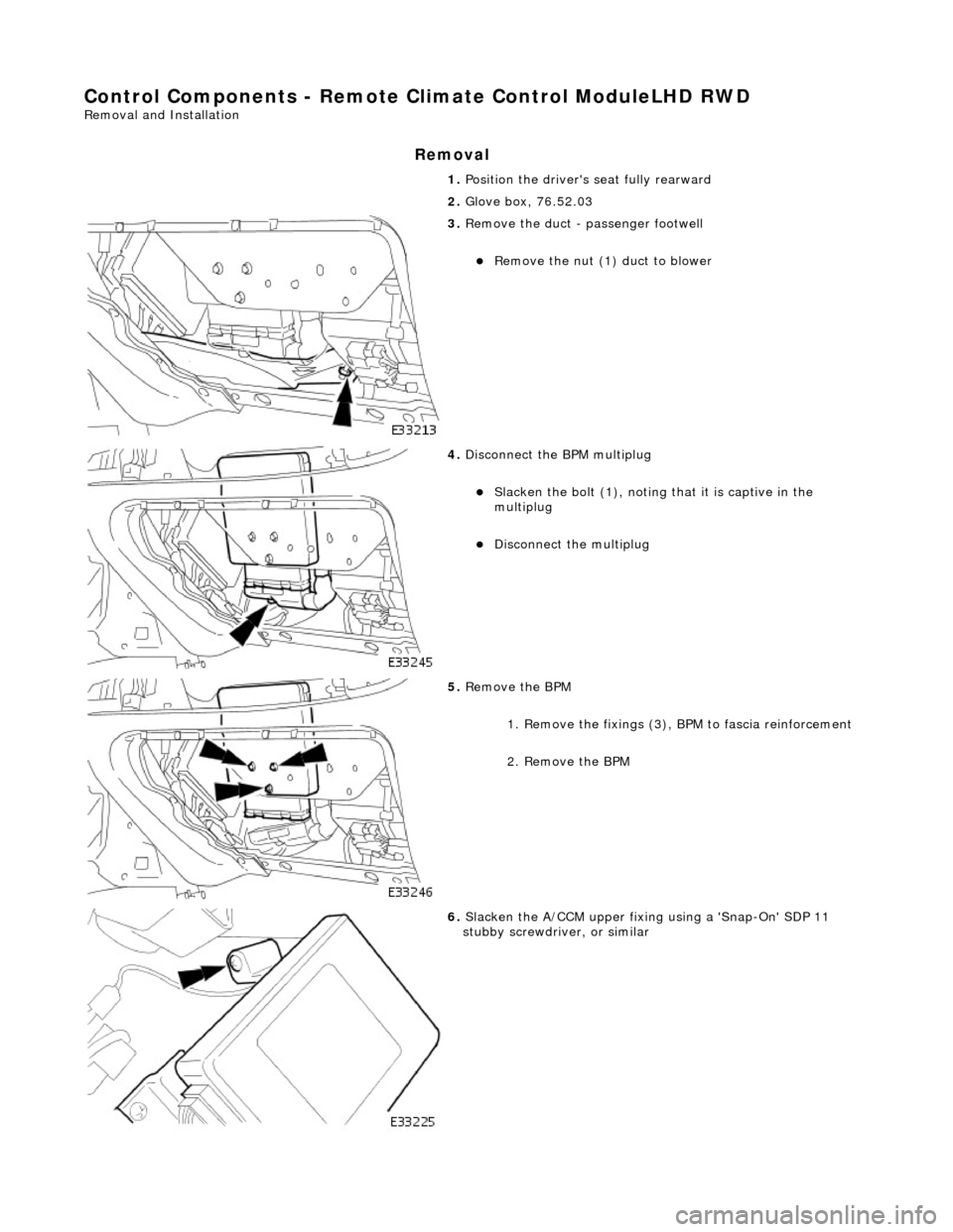
Control Components - Remote Climate Control ModuleLHD RWD
Removal and Installation
Removal
1. Position the driver's seat fully rearward
2. Glove box, 76.52.03
3. Remove the duct - passenger footwell
Remove the nut (1) duct to blower
4. Disconnect the BPM multiplug
Slacken the bolt (1), noting that it is captive in the
multiplug
Disconnect the multiplug
5. Remove the BPM
1. Remove the fixings (3), BPM to fascia reinforcement
2. Remove the BPM
6. Slacken the A/CCM upper fixing using a 'Snap-On' SDP 11
stubby screwdriver, or similar
Page 1848 of 2490
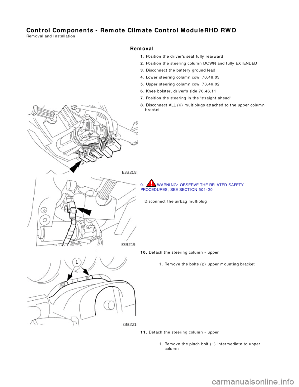
Control Components - Remote Climate Control ModuleRHD RWD
Removal and Installation
Removal
1. Position the driver's seat fully rearward
2. Position the steering column DOWN and fully EXTENDED
3. Disconnect the battery ground lead
4. Lower steering column cowl 76.46.03
5. Upper steering column cowl 76.46.02
6. Knee bolster, driver's side 76.46.11
7. Position the steering in the 'straight ahead'
8. Disconnect ALL (6) multiplugs attached to the upper column
bracket
9. WARNING: OBSERVE THE RELATED SAFETY
PROCEDURES, SEE SECTION 501-20
Disconnect the airbag multiplug
10. Detach the steering column - upper
1. Remove the bolts (2 ) upper mounting bracket
11. Detach the steering column - upper
1. Remove the pinch bolt (1) intermediate to upper column
Page 1853 of 2490
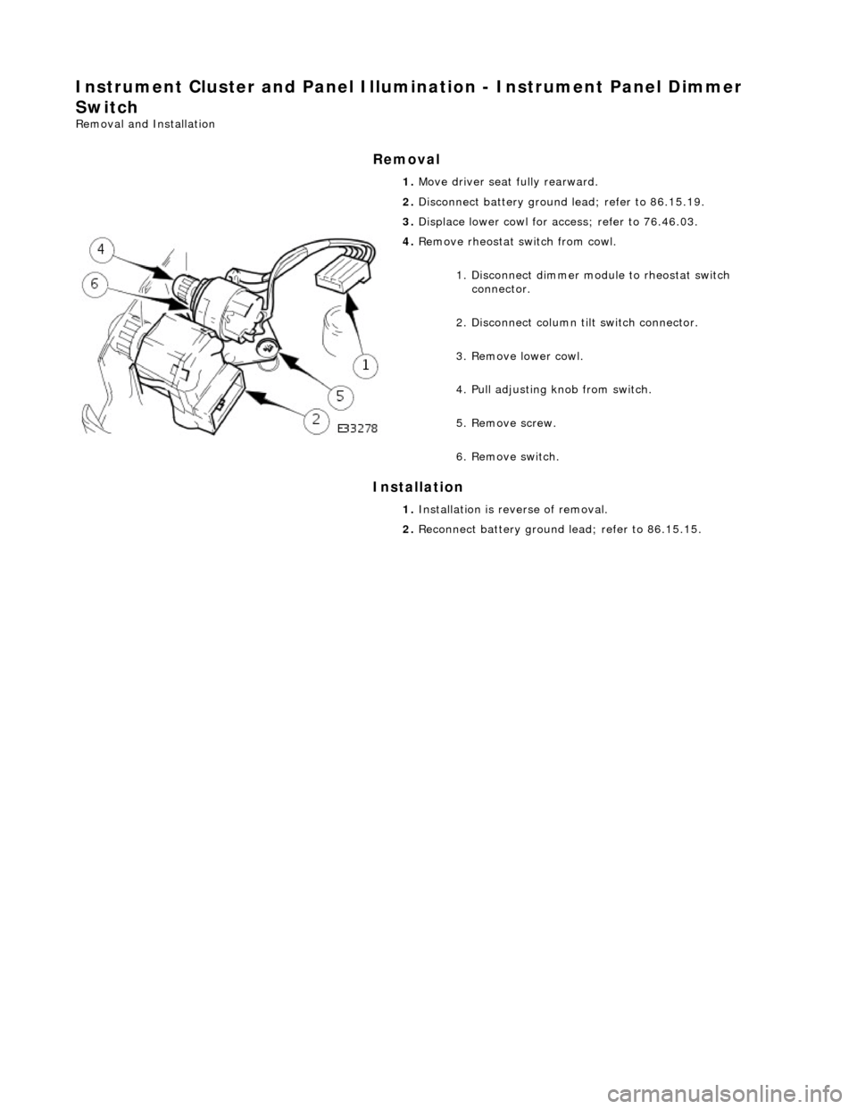
Instrument Cluster and Panel Illumination - Instrument Panel Dimmer
Switch
Removal and Installation
Removal
Installation
1.
Move driver seat fully rearward.
2. Disconnect battery ground lead; refer to 86.15.19.
3. Displace lower cowl for access; refer to 76.46.03.
4. Remove rheostat sw itch from cowl.
1. Disconnect dimmer module to rheostat switch connector.
2. Disconnect column tilt switch connector.
3. Remove lower cowl.
4. Pull adjusting knob from switch.
5. Remove screw.
6. Remove switch.
1. Installation is reverse of removal.
2. Reconnect battery ground lead; refer to 86.15.15.
Page 1858 of 2490
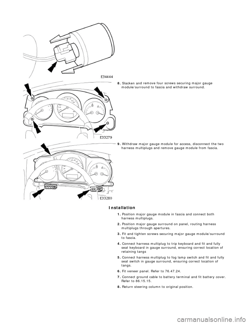
In
stallation
8.
Slac ken an
d remove four screws securing major gauge
module/surround to fascia and withdraw surround.
9. With draw major gau
ge module fo
r access, disconnect the two
harness multiplugs and remove gauge module from fascia.
1. Position major gauge module in fascia and connect both
harness multiplugs.
2. Position major gauge surround on panel, routing harness
multiplugs through apertures.
3. Fit and tighten screws securing major gauge module/surround
to fascia.
4. Connect harness multiplug to tr ip keyboard and fit and fully
seat keyboard in gauge surround, ensuring correct location of
retaining tangs
5. Connect harness multiplug to fog lamp switch and fit and fully
seat switch in gaug e surround, ensuring correct location of
tangs.
6. Fit veneer panel. Refer to 76.47.24.
7. Connect ground cable to battery terminal and fit battery cover.
Refer to 86.15.15.
8. Return steering column to original position.
Page 1925 of 2490
Exterior Lighting - Fog Lamp Switch
Removal and Installation
Removal
Installation
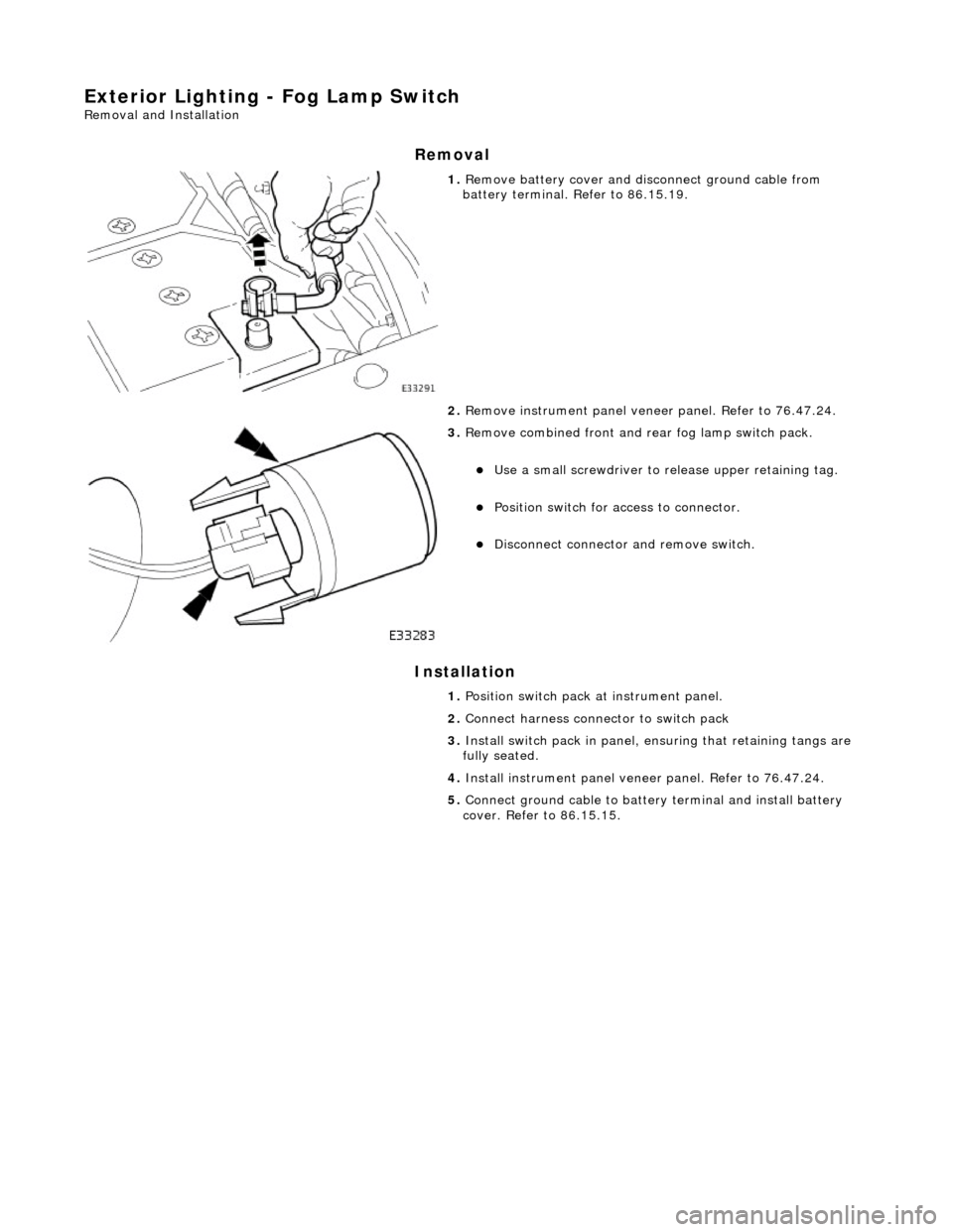
1. Remove battery cover and disc onnect ground cable from
battery terminal. Refer to 86.15.19.
2. Remove instrument pa nel veneer panel. Refer to 76.47.24.
3. Remove combined front and rear fog lamp switch pack.
Use a small screwdriver to re lease upper retaining tag.
Position switch for access to connector.
Disconnect connector and remove switch.
1. Position switch pack at instrument panel.
2. Connect harness connector to switch pack
3. Install switch pack in panel, ensuring that retaining tangs are
fully seated.
4. Install instrument panel veneer panel. Refer to 76.47.24.
5. Connect ground cable to batter y terminal and install battery
cover. Refer to 86.15.15.
Page 1927 of 2490
Exterior Lighting - Front Fog Lamp Bulb
Removal and Installation
Removal
Installation
1.
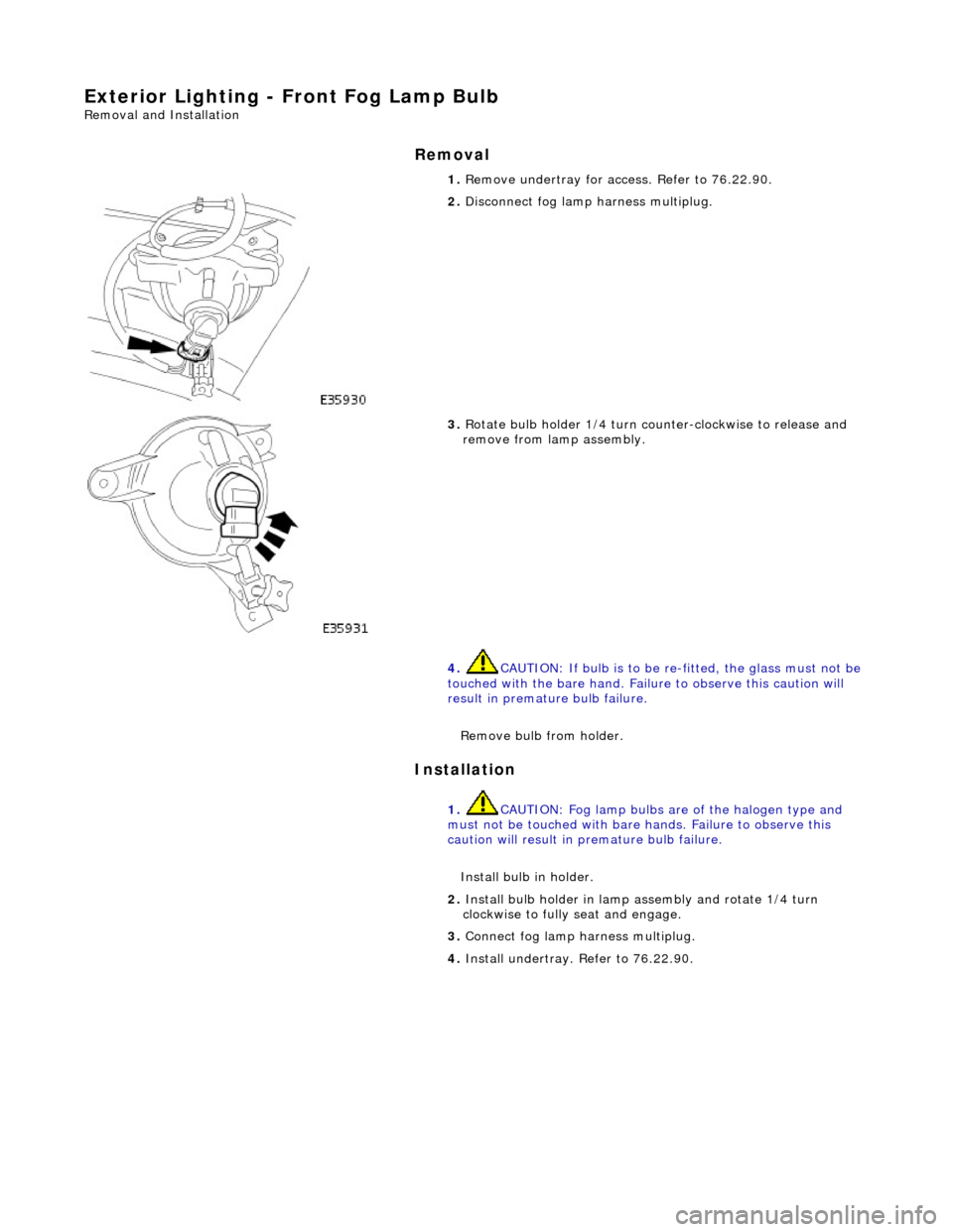
Remove undertray for ac cess. Refer to 76.22.90.
2. Disconnect fog lamp harness multiplug.
3. Rotate bulb holder 1/4 turn counter-clockwise to release and
remove from lamp assembly.
4. CAUTION: If bulb is to be re -fitted, the glass must not be
touched with the bare hand. Failure to observe this caution will
result in premature bulb failure.
Remove bulb from holder.
1. CAUTION: Fog lamp bulbs are of the halogen type and
must not be touched with bare hands. Failure to observe this
caution will result in premature bulb failure.
Install bulb in holder.
2. Install bulb holder in lamp assembly and rotate 1/4 turn
clockwise to fully seat and engage.
3. Connect fog lamp harness multiplug.
4. Install undertray. Refer to 76.22.90.