Seat JAGUAR X308 1998 2.G Workshop Manual
[x] Cancel search | Manufacturer: JAGUAR, Model Year: 1998, Model line: X308, Model: JAGUAR X308 1998 2.GPages: 2490, PDF Size: 69.81 MB
Page 1148 of 2490

Evaporative E
missions - Evaporative Emissions
Description an
d Operation
To reduce the emission of fuel vapour, th e fuel tank is vented to atmosphere through activated charcoal adsorption canister
(s) which collects the fuel droplets. The ch arcoal is periodically purged of fuel when the EVAP Canister Purge Valve opens
the vapour line between the canister(s) and the air intake induct ion elbow. This action allows manifold depression to draw
air through the canister atmospheric vent, taking up the deposited fuel from the charcoal adsorber and burning the resulting
fuel vapour in the engine.
The EVAP Canister Purge Valve is controlled by the engine management system ECM. Purging is carried out in accordance
with the engine management fu eling strategy (see below).
The fuel tank vapour outlet is via a removeable flange assemb ly on the top surface of the tank. The vapour storage canister
or canisters are fitted on the underside of the vehicle below the rear seats.
There are three variants of the evaporativ e system. All systems use the charcoal adsorber storage canisters and purge valve
and operate as described above. The specific features of each system are described below. The evaporative systems are
designated as :
sin g
le canister system
ru
nn
ing loss system
ru
nn
ing loss with On-board Re-fueling Vapour Recovery (ORVR) system
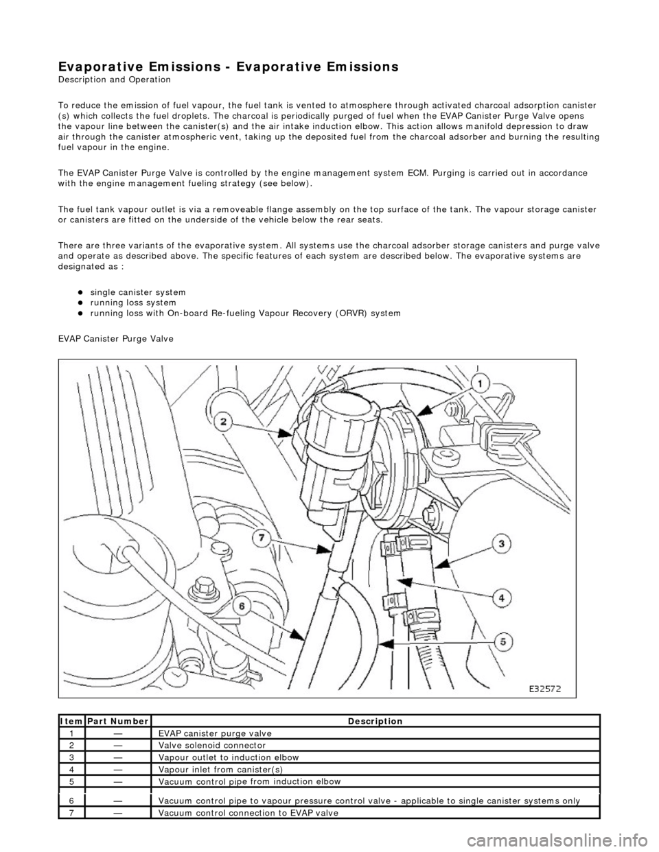
EVAP Canister Purge Valve
Ite
m
Par
t
Number
De
scr
iption
1—EVAP canister purge v
alve
2—Valve s
olenoid connector
3—Vapour outlet to indu
ction elbow
4—Vapour
inlet from canister(s)
5—Vacuum contro
l pi
pe from induction elbow
6—Vacuum contro
l pi
pe to vapour pressure control va
lve - applicable to single canister systems only
7—Vacuum
control connection to EVAP valve
Page 1174 of 2490

Installation
1.
Insta ll n
ew sealing ring. Make sure it is seated correctly.
2. Connect fuel pump link lead to flange connector.
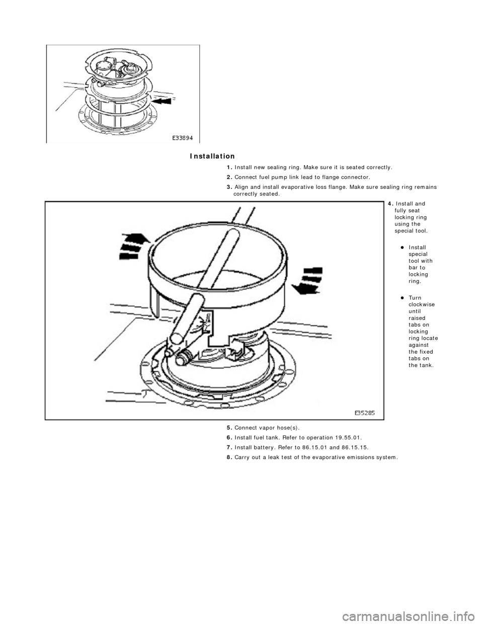
3. Align and install evaporative loss flange. Make sure sealing ring remains
correctly seated.
4. Insta ll a
nd
fully seat
locking ring
using the
special tool.
Insta ll
special
tool with
bar t
o
locking
ring.
Turn
clock w
ise
until
raised
tabs on
locking
ring locate
against
the fixed
tabs on
the tank.
5. Connect vapor hose(s).
6. Install fuel tank. Refer to operation 19.55.01.
7. Install battery. Refer to 86.15.01 and 86.15.15.
8. Carry out a leak test of the evaporative emissions system.
Page 1431 of 2490

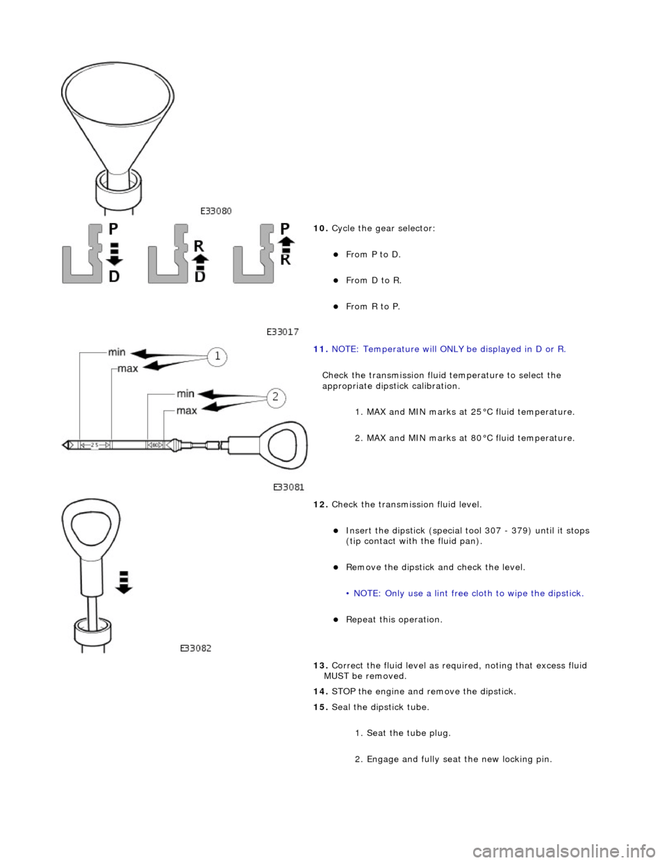
10. Cycle the gear selector:
From P to D.
From D to R.
From R to P.
11. NOTE: Temperature will ONLY be displayed in D or R.
Check the transmission fluid temperature to select the
appropriate dipstick calibration. 1. MAX and MIN marks at 25°C fluid temperature.
2. MAX and MIN marks at 80°C fluid temperature.
12. Check the transmission fluid level.
Insert the dipstick (special tool 307 - 379) until it stops
(tip contact with the fluid pan).
Remove the dipstick an d check the level.
• NOTE: Only use a lint free cloth to wipe the dipstick.
Repeat this operation.
13. Correct the fluid leve l as required, noting that excess fluid
MUST be removed.
14. STOP the engine and remove the dipstick.
15. Seal the dipstick tube.
1. Seat the tube plug.
2. Engage and fully seat the new locking pin.
Page 1487 of 2490

Automatic Transmission/Transaxle External Controls - 4.0L NA V8 -
AJ27/3.2L NA V8 - AJ 26 - Selector Lever Cable and Bracket
Removal and Installation
Removal
1. Position the selector to N.
2. Remove the J-gate surround, Section 501-05.
3. Remove the console finisher ve neer panel, Section 501-12.
4. Remove the center console assembly, Section 501-12.
5. Raise the vehicle for access.
6. Detach the selector cable from the transmission unit.
1. Remove the cable inner to selector lever nut.
2. Remove the cable to transmission casing fixings.
7. Reposition the selector cable.
8. Remove the LH front seat, Section 501-10.
9. Reposition the LH floo r carpet for access.
10. Remove the selector cable to tunnel clip tie strap.
11. Detach the selector cable from the gear shift assembly.
1. Remove the inner cable to shift lever nut.
2. Slacken the outer cable locknuts.
Page 1490 of 2490

Automatic Transmission/Transaxle External Controls - 4.0L NA V8 -
AJ27/3.2L NA V8 - AJ 26 - Selector Lever Gate Finish Panel
Removal and Installation
Removal
Installation
1.
Apply protective tape to veneer along each side of 'J' gate
finisher.
2. Using a screwdriver in the slot in front of the finisher,
carefully lift the finisher an d ease it from the 'J' gate
surround.
1. Position finisher over gear selector.
2. Firmly seat finisher on veneer panel.
3. Remove protective tape from ve neer panel and using a suitable
cleaner, remove any residual adhesive.
Page 1513 of 2490

Automatic Transmission/Transaxle External Contro ls - 4.0L SC V8 - AJ26 -
Selector Lever Cable and Bracket
Removal and Installation
Removal
1. Disconnect the vehicle battery ground lead.
2. Position the selector to N.
3. Remove the J-gate surround, Section 501-05.
4. Remove the console finisher ve neer panel, Section 501-12.
5. Remove the center console assembly, Section 501-12.
6. Raise the vehicle for access.
7. Detach the gear selector cable from the transmission unit.
1. Remove the nut which secures the selector cable ball pin to the selector lever.
2. Lower the transmissi on lift for access.
3. Remove the bolts which secure the selector cable to the transmission casing.
8. Reposition the selector cable.
9. Remove the LH front seat, Section 501-10.
10. Reposition the LH floo r carpet for access.
11. Remove the selector cable to tunnel clip tie strap.
12. Detach the selector cable from the gear shift assembly.
1. Remove the inner cable to shift lever nut.
Page 1516 of 2490

Automatic Transmission/Transaxle External Contro ls - 4.0L SC V8 - AJ26 -
Selector Lever Gate Finish Panel
Removal and Installation
Removal
Installation
1.
Apply protective tape to veneer along each side of 'J' gate
finisher.
2. Using a screwdriver in the slot in front of the finisher,
carefully lift the finisher an d ease it from the 'J' gate
surround.
1. Position finisher over gear selector.
2. Firmly seat finisher on veneer panel.
3. Remove protective tape from ve neer panel and using a suitable
cleaner, remove any residual adhesive.
Page 1738 of 2490

4. Full
y seat the tank into positi
on, ensuring that no harness
wiring is trapped.
5. On non-
ORVR vehicles, reconnec
t the trunk lid lefthand strut
rear pivot.
1. Fit the retaining clip on to the end of the trunk lid strut and fit the strut to the trunk lid pivot. Re-
position retaining clip to secure the strut.
Re
move any temporary trunk lid supports and check that
the lid operates correctly.
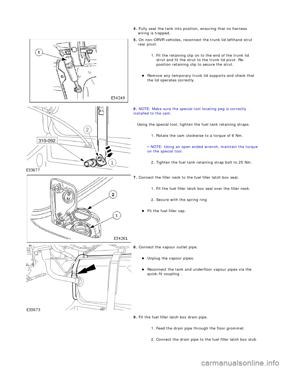
6. NOTE
: Make sure the special tool locating peg is correctly
installed to the cam.
Using the special tool, tighten the fuel tank retaining straps.
1. Rotate the cam clockwise to a torque of 6 Nm.
• NOTE: Using an open ended wrench, maintain the torque
on the special tool.
2. Tighten the fuel tank reta ining strap bolt to 25 Nm.
7. Connect the fi
ller neck to the fuel filler latch box seal.
1. Fit the fuel filler latch box seal over the filler neck.
2. Secure with the spring ring
F i
t the fuel filler cap.
8. Connect the vapour outlet pip
e.
Unplug the v
a
pour pipes.
Reconn
ect th
e tank and underfloor vapour pipes via the
quick-fit coupling .
9. Fit the fuel filler latch box drain pipe.
1. Feed the drain pipe th rough the floor grommet.
2. Connect the drain pipe to the fuel filler latch box stub
Page 1739 of 2490

pipe.
3
. Tie the drain pipe to th
e filler tube using a ratchet
strap. Trim strap.
10
.
Reconnect the trunk harness connections.
1. If fitted, connect the wi ring to the accelerometer.
2. Connect the wiring to the fuel level sensor harness.
3. Connect the wiring to th e fuel pump connector.
4. If fitted, connect the wiring to the pressure sensor connector.
11
.
Reconnect the lefthand side trunk harness if it has been
necessary to move it for access. Route the harness behind both
the filler tube and breather or pressure relief pipe.
1. Fit the harness securing cl ip to the mounting bracket.
2. Connect the fuel flap lock actuator connector.
3. Connect the lefthand rear lamp harness connector.
4. If applicable, feed the side marker lamp harness through the access hole in the floor and reseat the
sealing grommet.
On
the underside of the vehicl
e, fit the side marker lamp
connector and fix the harness to the securing clips.
12
.
On the underside of the vehicle, fit the drain pipe to the
securing clip.
13. On the underside of the vehicle, reconnect the fuel feed and
return pipes.
R
emove the plugs from the tank
and fuel feed and return
Page 1742 of 2490

In
stallation
8.
Ro
ute the throttle cable through the water deflector bracket.
9. Ensure the drivers seat is fully rearward.
10. Remove the A-Pillar lower trim pad.
11. Di
sconnect the throttle cable from the pedal.
1. Remove the throttle cable split pin.
2. Remove the throttle cable retaining sleeve.
3. Disconnect the throttle cable.
12. From under the hood, remove the cable from the vehicle.
1. Installation is th e reverse of the re moval procedure.
Adjust th
e throttle cabl
e, refer to 19.20.08.