Seat JAGUAR X308 1998 2.G Workshop Manual
[x] Cancel search | Manufacturer: JAGUAR, Model Year: 1998, Model line: X308, Model: JAGUAR X308 1998 2.GPages: 2490, PDF Size: 69.81 MB
Page 882 of 2490

Installation
20. Clean and inspect all relevant components.
1. Push the tensioner piston (secon dary chain) into the body to
provide clearance for fitting.
1. Insert a thin rigid wire th rough the hole in the end of
the tensioner piston to displace the ball from the non-
return valve seat.
2. With the wire in position, press the piston fully into the tensioner body.
Remove the wire.
2. Fit the VVT unit to the engine.
Assemble the VVT unit, the exhaust camshaft sprocket
and the secondary chain, in pr eparation for fitting to the
engine.
1. Fit the above assembly to the camshafts with the chain correctly positioned over the tensioner; VVT
unit to the inlet and the sprocket to the exhaust.
2. Fit, but do not tighten, each bolt which secures the VVT unit and the exhaust sprocket to the camshafts.
Allow the VVT unit sufficien t space to fit the primary
chain, in a la ter operation.
3. Fit the chain tensioning tool 303 - 532 to the exhaust camshaft
sprocket.
Reposition the sprocket (and the VVT unit) for the most
advantageous position for use of the tool.
Remove the tool.
4. Refit the primary timing chain.
1. Lift the primary chain an d position it over the VVT
unit sprocket (the VVT unit mu st be pulled forward to
clear the cylinder head casting). There must be no
slack on the drive side of the primary chain and the
VVT unit must not be rotated on the camshaft.
2. Slide the VVT unit fully on to the camshaft.
5. Fit the primary chain tensioner blade.
1. Position the tensioner blade to the cylinder block.
Page 887 of 2490

Installation
15. Remove the primary ch ain tensioner blade.
1. Remove the pivot bolt which secures the tensioner blade.
2. Remove the tensioner blade.
16. Disconnect the primary chain from the VVT unit and the
crankshaft sprocket, and remove it completely.
17. Do not tamper with the three bolts which secure the VVT
mechanism to the sprockets. It is sealed at the factory to the
correct valve timing specificatio n for the engine and is supplied
only as a complete unit.
18. Remove the VVT unit.
1. Remove the securing bolt from both the VVT unit and
the exhaust cam sprocket.
2. Remove the VVT unit, exhaust sprocket and secondary chain as an asse mbly (release the chain
from the tensioner which is still secured to the
cylinder head).
Remove the secondary chain from the VVT unit and the
sprocket.
19. Clean and inspect all relevant components.
1. Push the tensioner piston (secon dary chain) into the body to
provide clearance for fitting.
1. Insert a thin rigid wire th rough the hole in the end of
the tensioner piston to displace the ball from the non-
return valve seat.
2. With the wire in position, press the piston fully into the tensioner body.
Remove the wire.
2. Fit the VVT unit to the engine.
Assemble the VVT unit, the exhaust camshaft sprocket
and the secondary chain, in pr eparation for fitting to the
engine.
1. Fit the above assembly to the camshafts with the chain correctly positioned over the tensioner; VVT
unit to the inlet and the sprocket to the exhaust.
2. Fit, but do not tighten, each bolt which secures the VVT unit and the exhaust sprocket to the camshafts.
Page 919 of 2490
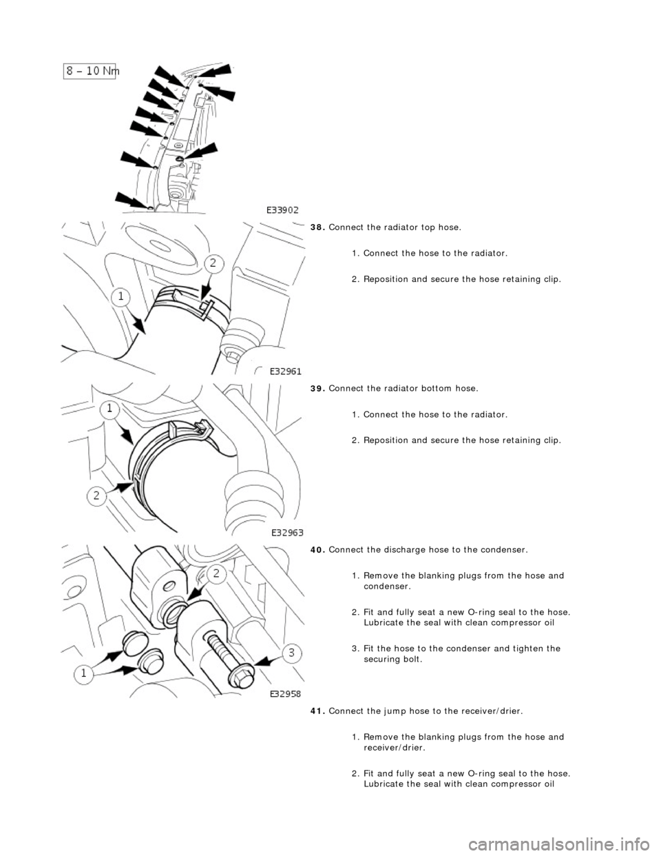
38
.
Connect the radiator top hose.
1. Connect the hose to the radiator.
2. Reposition and secure the hose retaining clip.
39
.
Connect the radiator bottom hose.
1. Connect the hose to the radiator.
2. Reposition and secure the hose retaining clip.
40
.
Connect the discharge hose to the condenser.
1. Remove the blanking plugs from the hose and condenser.
2. Fit and fully seat a new O-ring seal to the hose.
Lubricate the seal with clean compressor oil
3. Fit the hose to the condenser and tighten the securing bolt.
41. Connect the jump hose to the receiver/drier.
1. Remove the blanking plugs from the hose and receiver/drier.
2. Fit and fully seat a new O-ring seal to the hose.
Lubricate the seal with clean compressor oil
Page 920 of 2490
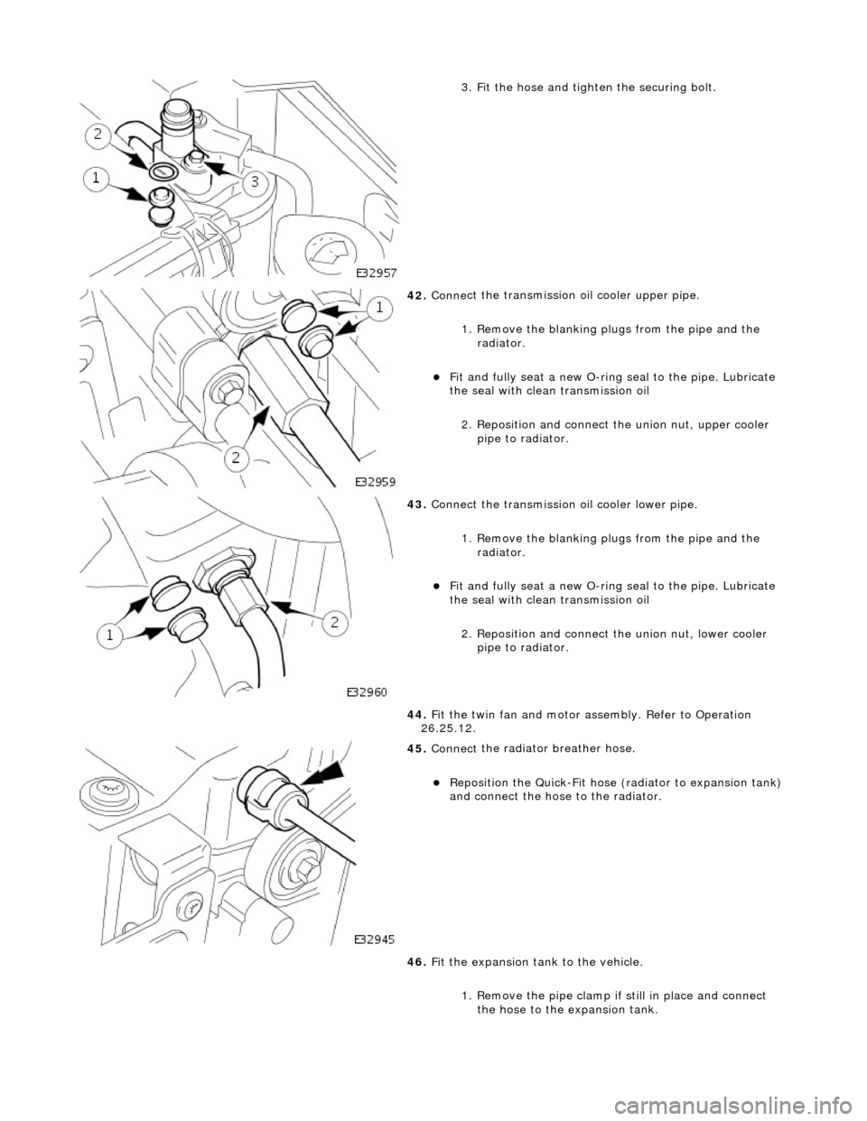
3.
Fit the hose and tighten the securing bolt.
42 . Conne
ct the transmission
oil cooler upper pipe.
1. Remove the blanking plugs from the pipe and the radiator.
Fit and
fully seat a new O-ring
seal to the pipe. Lubricate
the seal with clean transmission oil
2. Reposition and connect the union nut, upper cooler pipe to radiator.
43 . Conne
ct the transmission oil cooler lower pipe.
1. Remove the blanking plugs from the pipe and the radiator.
Fit and
fully seat a new O-ring
seal to the pipe. Lubricate
the seal with clean transmission oil
2. Reposition and connect the union nut, lower cooler
pipe to radiator.
44. Fit the twin fan and motor assembly. Refer to Operation
26.25.12.
45 . Connect
the radiator breather hose.
Re
po
sition the Quick-Fit hose (radiator to expansion tank)
and connect the hose to the radiator.
46. Fit the expansion tank to the vehicle.
1. Remove the pipe clamp if still in place and connect
the hose to the expansion tank.
Page 954 of 2490
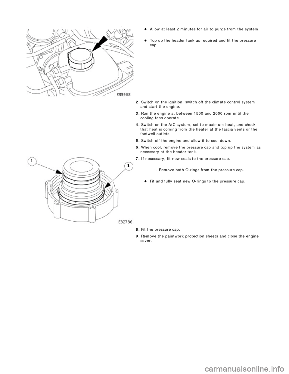
Allow at least 2 minutes f
or ai
r to purge from the system.
Top up the he
ader tank as re
quired and fit the pressure
cap.
2. Switch on the ignition, switch off the climate control system
and start the engine.
3. Run the engine at between 1500 and 2000 rpm until the
cooling fans operate.
4. Switch on the A/C system, set to maximum heat, and check
that heat is coming from the heat er at the fascia vents or the
footwell outlets.
5. Switch off the engine and allow it to cool down.
6. When cool, remove the pressure cap and top up the system as
necessary at the header tank.
7. If n e
cessary, fit new seals to the pressure cap.
1. Remove both O-rings from the pressure cap.
Fit and
fully seat new O-rings to the pressure cap.
8. Fit the pressure cap.
9. Remove the paintwork protection sheets and close the engine
cover.
Page 957 of 2490
9.
R
un the engine at between 1500 and 2000 rpm until the
cooling fans operate.
10. Switch on the climate control system, set to maximum heat,
and check that heat is coming from the heater at the fascia
vents or the footwell outlets.
11. Switch off the engine and allow it to cool down.
12. When cool, remove the pressure cap and top up the system
as necessary at the header tank.
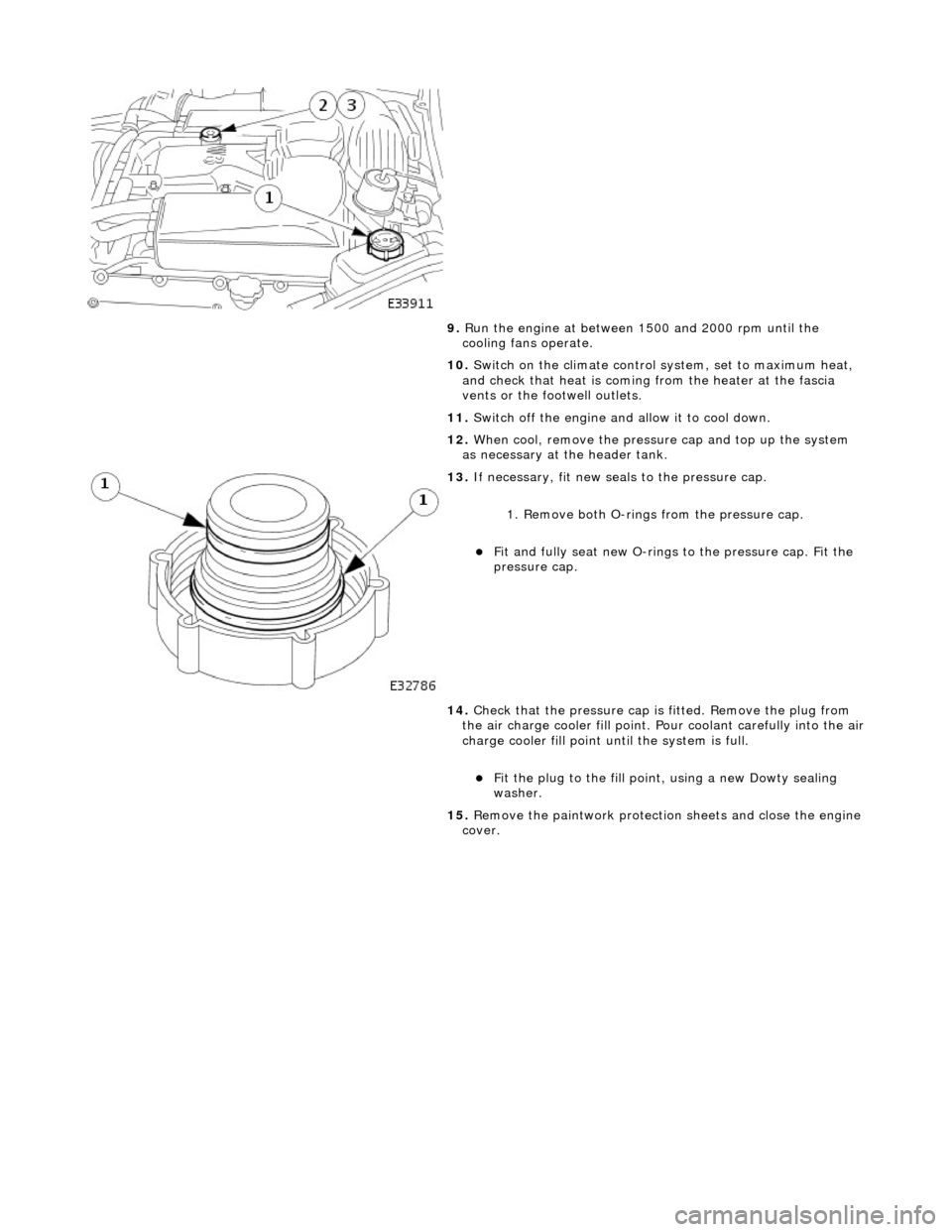
13
.
If necessary, fit new seals to the pressure cap.
1. Remove both O-rings from the pressure cap.
Fit and
fully seat new O-rings
to the pressure cap. Fit the
pressure cap.
14. Check that the pressure cap is fitted. Remove the plug from
the air charge cooler fill point. Pour coolant carefully into the air
charge cooler fill point until the system is full.
F
it the plug to the fill poin
t, using a new Dowty sealing
washer.
15. Remove the paintwork protection sheets and close the engine
cover.
Page 1032 of 2490
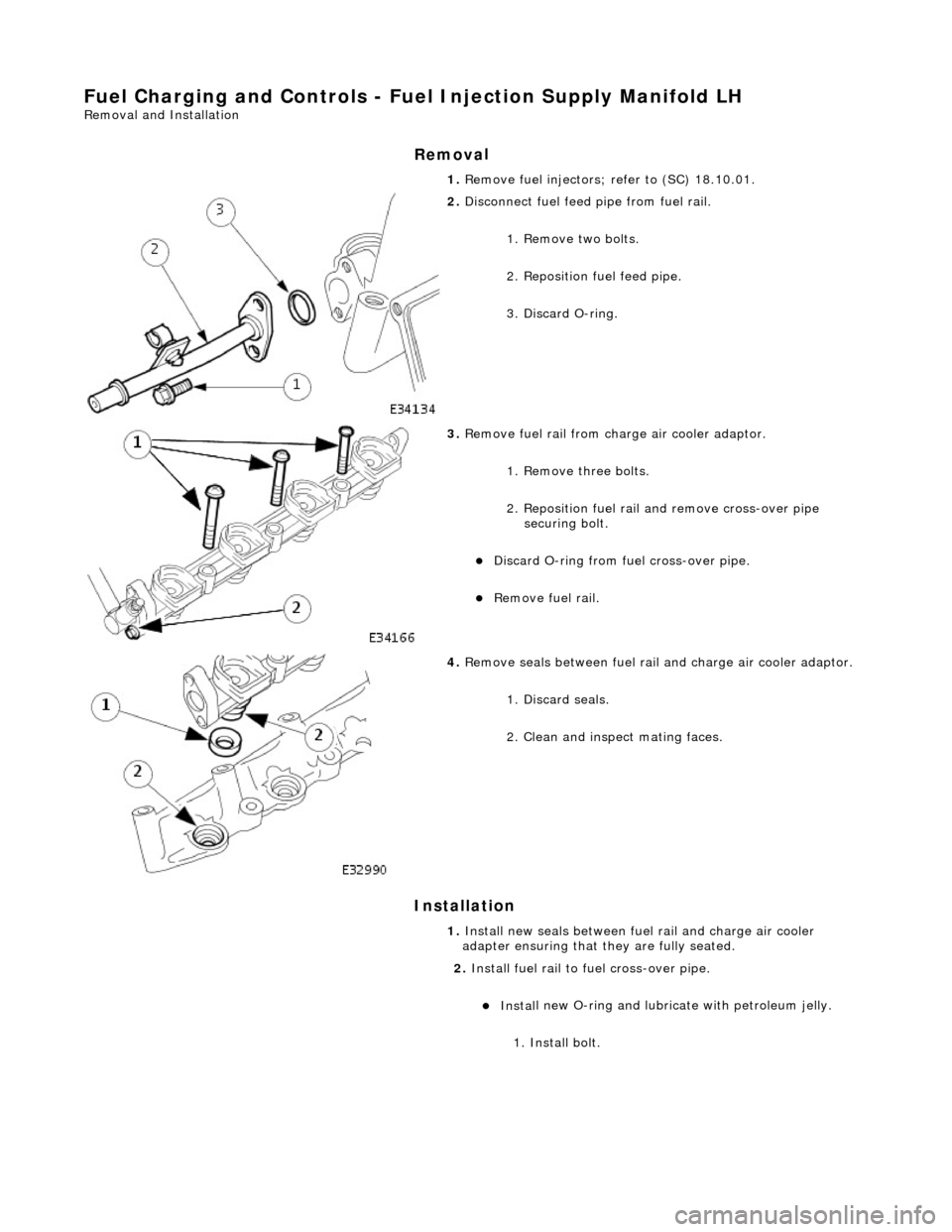
Fuel Char
ging and Controls - Fu
el Injection Supply Manifold LH
Remo
val and Installation
Remov
a
l
Installation
1. Re
move fuel injectors; refer to (SC) 18.10.01.
2. Disc
onnect fuel feed
pipe from fuel rail.
1. Remove two bolts.
2. Reposition fuel feed pipe.
3. Discard O-ring.
3. Re
move fuel rail from charge air cooler adaptor.
1. Remove three bolts.
2. Reposition fuel rail and remove cross-over pipe securing bolt.
Di
scard O-ring from fuel cross-over pipe.
R
e
move fuel rail.
4. Re
move seals between fuel rail
and charge air cooler adaptor.
1. Discard seals.
2. Clean and inspect mating faces.
1. Install new seals between fuel rail and charge air cooler
adapter ensuring that they are fully seated.
2. Install fuel rail to fuel cross-over pipe.
Inst al
l new O-ring and lubricate with petroleum jelly.
1. Install bolt.
Page 1035 of 2490

I
nstallation
1.
Inst
all new seals between fuel rail and charge air cooler
adapter, ensuring they are fully seated.
2. Install
fuel rail to fuel cross-over pipe.
1. Install new O-ring and lubricate with petroleum jelly.
2. Install bolt.
3. Install
fuel rail to charge air cooler adaptor.
1. Align fuel rail to adaptor; still connected to fuel crossover pipe and fuel return pipe. Locate fuel rail
into adaptor.
2. Install three bolts which se cure fuel rail to adaptor.
Tighten to 18-24 Nm.
4. Install
fuel pressure regulator.
Install a new O-r
ing to fu
el pressure regulator and
lubricate with petroleum jelly
1. Install bolts.
5. Install fuel injectors; refer to (SC) 18.10.01.
Page 1127 of 2490
I
nstallation
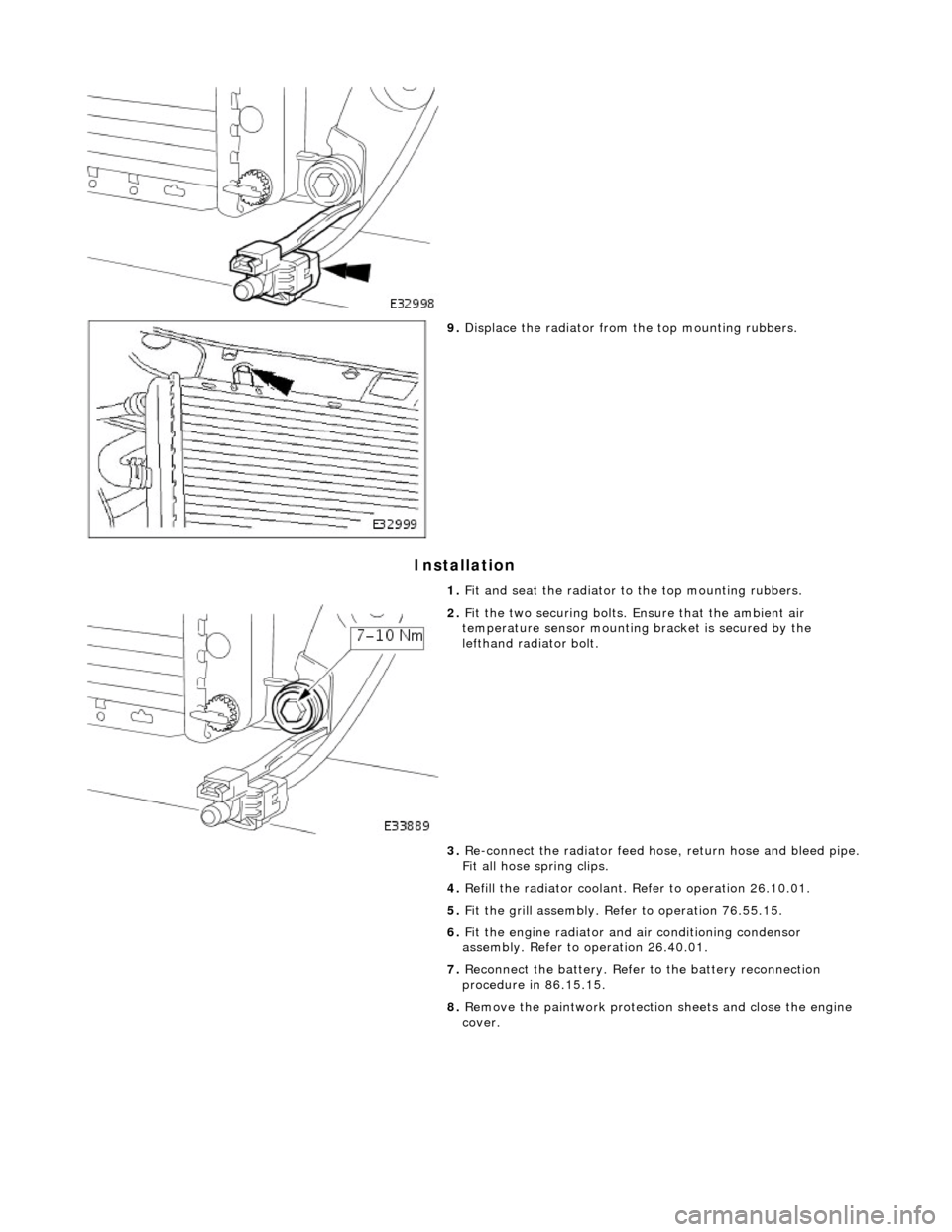
9.
Di
splace the radiator from
the top mounting rubbers.
1. Fit and seat the radiator to the top mounting rubbers.
2. F
it the two securing bolts.
Ensure that the ambient air
temperature sensor mounting bracket is secured by the
lefthand radiator bolt.
3. Re-connect the radiator feed ho se, return hose and bleed pipe.
Fit all hose spring clips.
4. Refill the radiator coolant. Refer to operation 26.10.01.
5. Fit the grill assembly. Refer to operation 76.55.15.
6. Fit the engine radiator and air conditioning condensor
assembly. Refer to operation 26.40.01.
7. Reconnect the battery. Refer to the battery reconnection
procedure in 86.15.15.
8. Remove the paintwork protection sheets and close the engine
cover.
Page 1140 of 2490
In
stallation
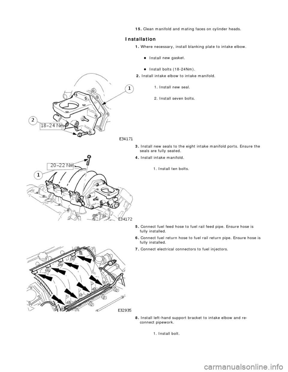
15.
Cle
an manifold and mating faces on cylinder heads.
1. Where necessary, install blanking plate to intake elbow.
Inst al
l new gasket.
Inst
al
l bolts (18-24Nm).
2. Inst al
l intake elbow to intake manifold.
1. Install new seal.
2. Install seven bolts.
3. Install new seals to the eight intake manifold ports. Ensure the
seals are fully seated.
4. Inst al
l intake manifold.
1. Install ten bolts.
5. Connect fuel feed hose to fuel rail feed pipe. Ensure hose is
fully installed.
6. Connect fuel return hose to fuel rail return pipe. Ensure hose is
fully installed.
7. Con n
ect electrical connectors to fuel injectors.
8. Install left-hand support brac ket to intake elbow and re-
connect pipework.
1. Install bolt.