torque JAGUAR X308 1998 2.G Workshop Manual
[x] Cancel search | Manufacturer: JAGUAR, Model Year: 1998, Model line: X308, Model: JAGUAR X308 1998 2.GPages: 2490, PDF Size: 69.81 MB
Page 1382 of 2490

Automatic Transmission/Transaxle - 4.0L NA V8 - AJ27/3.2L NA V8 - AJ26
- Torque Converter
Disassembly and Assembly of Subassemblies
Special Tool(s)
Lifting handle
307-139
1. Remove the transmission unit from the vehicle; 44.20.01.
2. Remove the torque converter from the transmission unit.
пЃ¬Install lifting handles 307 - 139.
3. Remove lifting handles 307 - 139 from the torque converter.
4. Clean the torque conver ter and mating faces.
5. CAUTIONS:
Use extreme care NOT to damage the oil seal with the
converter spigot.
Ensure that the conver ter is fully located.
Install the torque converter.
1. Install lifting handles 307 - 139.
2. Lubricate the front pump seal.
пЃ¬To facilitate location, rotate the converter as it is being
fitted and note the engagement of splines and oil pump
drive.
6. Check that the three conver ter fixing boss faces are
approximately 8,0 mm proud of the transmission mounting
face.
7. Remove lifting handles 307 - 139 from the torque converter.
8. Install the transmission unit; refer to Operation 44.20.01,
noting especially the alignment instructions.
Page 1383 of 2490
Automatic Transmission/Transaxle - 4.0L NA V8 - AJ27/3.2L NA V8 - AJ26
- Transmission
Installation
Installation
Special Tool(s)
Engine support
303-021
Engine lifting brackets
303-536
1. Clean all mating faces and relevant parts.
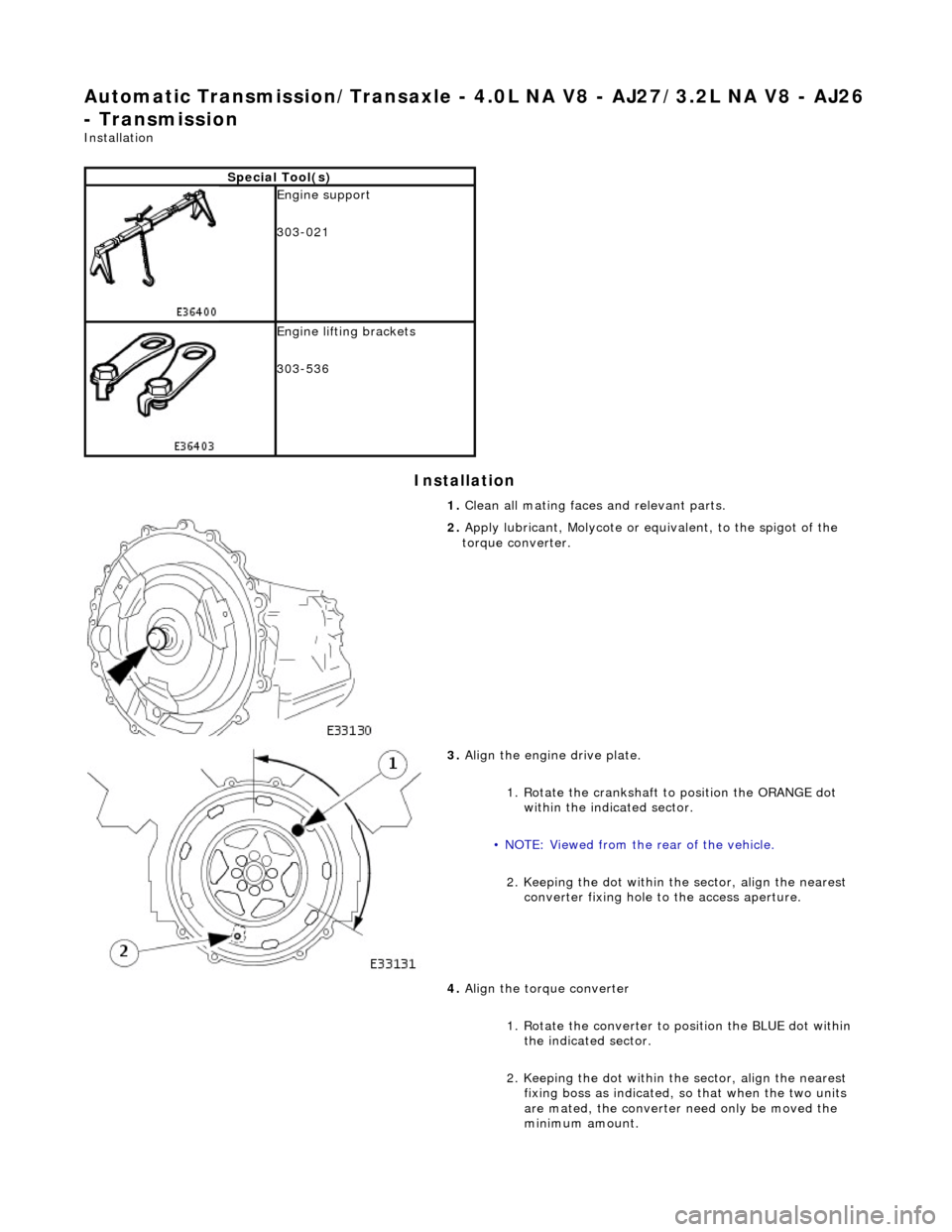
2. Apply lubricant, Molycote or equivalent, to the spigot of the
torque converter.
3. Align the engine drive plate.
1. Rotate the crankshaft to position the ORANGE dot
within the indicated sector.
• NOTE: Viewed from the rear of the vehicle.
2. Keeping the dot within the sector, align the nearest converter fixing hole to the access aperture.
4. Align the torque converter
1. Rotate the converter to position the BLUE dot within the indicated sector.
2. Keeping the dot within the sector, align the nearest fixing boss as indicated, so that when the two units
are mated, the converter need only be moved the
minimum amount.
Page 1384 of 2490
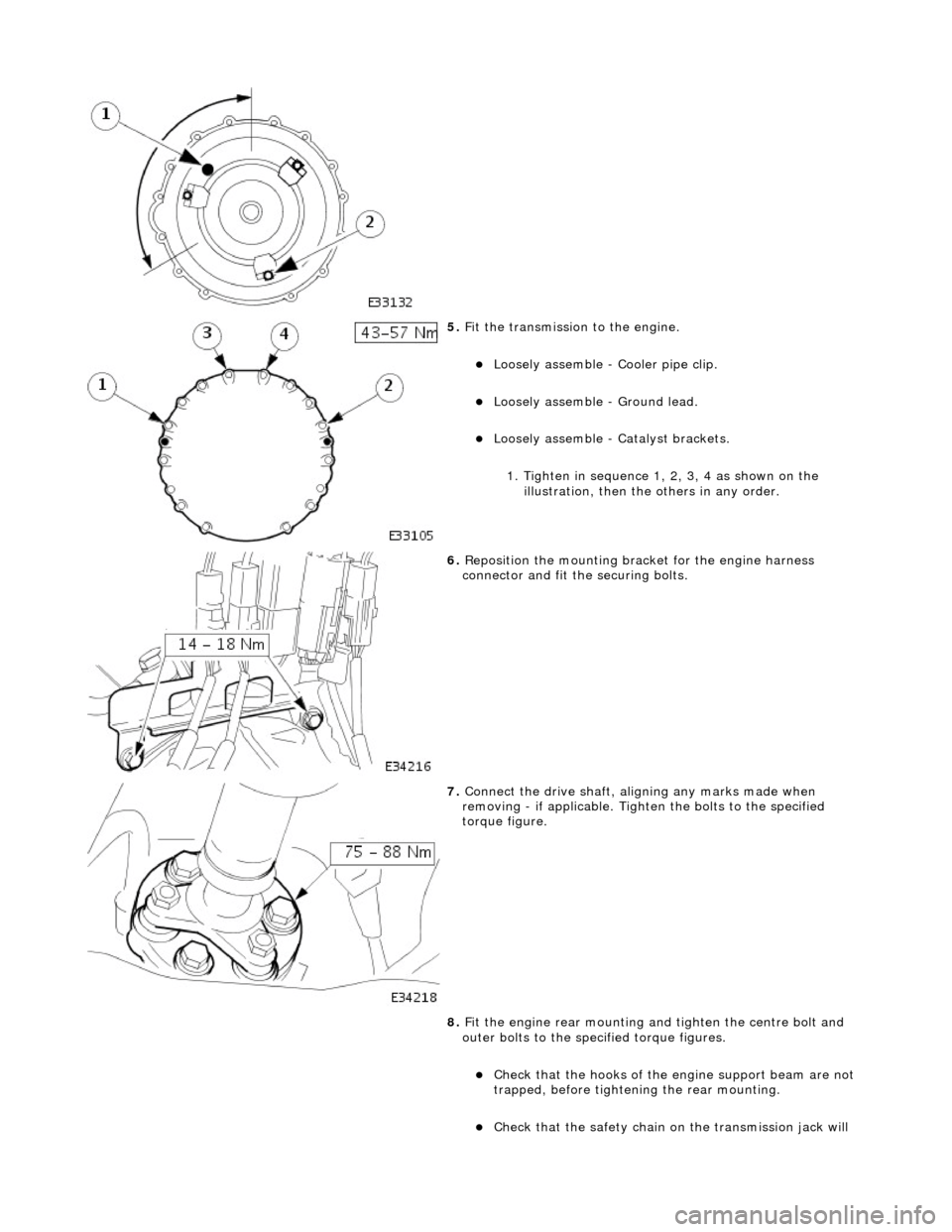
5. Fit the transmission to the engine.
пЃ¬Loosely assemble - Cooler pipe clip.
пЃ¬Loosely assemble - Ground lead.
пЃ¬Loosely assemble - Ca talyst brackets.
1. Tighten in sequence 1, 2, 3, 4 as shown on the illustration, then the others in any order.
6. Reposition the mounting brac ket for the engine harness
connector and fit the securing bolts.
7. Connect the drive shaft, aligning any marks made when
removing - if applicable. Tighten the bolts to the specified
torque figure.
8. Fit the engine rear mounting and tighten the centre bolt and
outer bolts to the specified torque figures.
пЃ¬Check that the hooks of the engine support beam are not
trapped, before tighteni ng the rear mounting.
пЃ¬Check that the safety chain on the transmission jack will
Page 1385 of 2490

not be trapped when the mounting is fitted.
9. Remove the transmission jack.
10. Fit the three bolts which secure the torque converter to the
drive plate.
1. Loosely assemble all three drive plate to torque converter bolts. Whilst preventing crankshaft
rotation, tighten the three converter bolts to the
specified torque figure.
2. Fit the blanking plug.
11. Connect the transmission harness multiplug.
1. Engage the multiplug.
2. Rotate the locking lever to secure.
12. Connect the selector cable to the selector lever and fit the
abutment bracket to the transmission casing. Tighten the nut
and two bolts to the specified torque figure.
Page 1386 of 2490
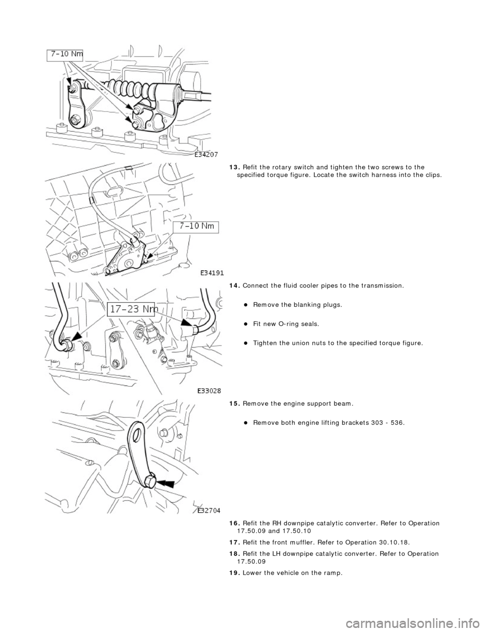
13. Refit the rotary switch and tighten the two screws to the
specified torque figure. Locate the switch harness into the clips.
14. Connect the fluid cooler pipes to the transmission.
пЃ¬Remove the blanking plugs.
пЃ¬Fit new O-ring seals.
пЃ¬Tighten the union nuts to the specified torque figure.
15. Remove the engine support beam.
пЃ¬Remove both engine lifting brackets 303 - 536.
16. Refit the RH downpipe catalytic converter. Refer to Operation
17.50.09 and 17.50.10
17. Refit the front muffler. Refer to Operation 30.10.18.
18. Refit the LH downpipe catalytic converter. Refer to Operation
17.50.09
19. Lower the vehicle on the ramp.
Page 1387 of 2490
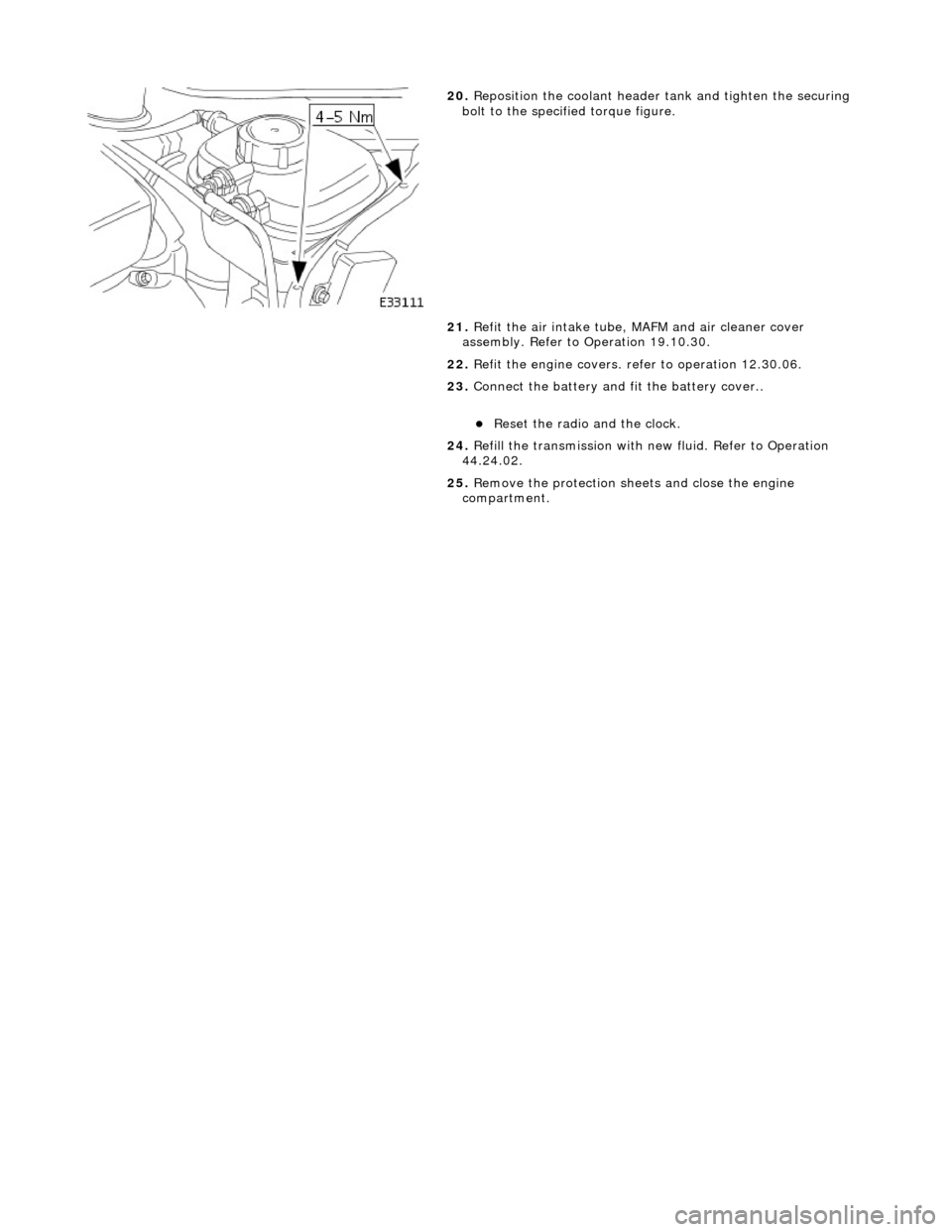
20. Reposition the coolant header tank and tighten the securing
bolt to the specified torque figure.
21. Refit the air intake tube, MAFM and air cleaner cover
assembly. Refer to Operation 19.10.30.
22. Refit the engine covers. re fer to operation 12.30.06.
23. Connect the battery and fit the battery cover..
пЃ¬Reset the radio and the clock.
24. Refill the transmission with new fluid. Refer to Operation
44.24.02.
25. Remove the protection sheets and close the engine
compartment.
Page 1388 of 2490
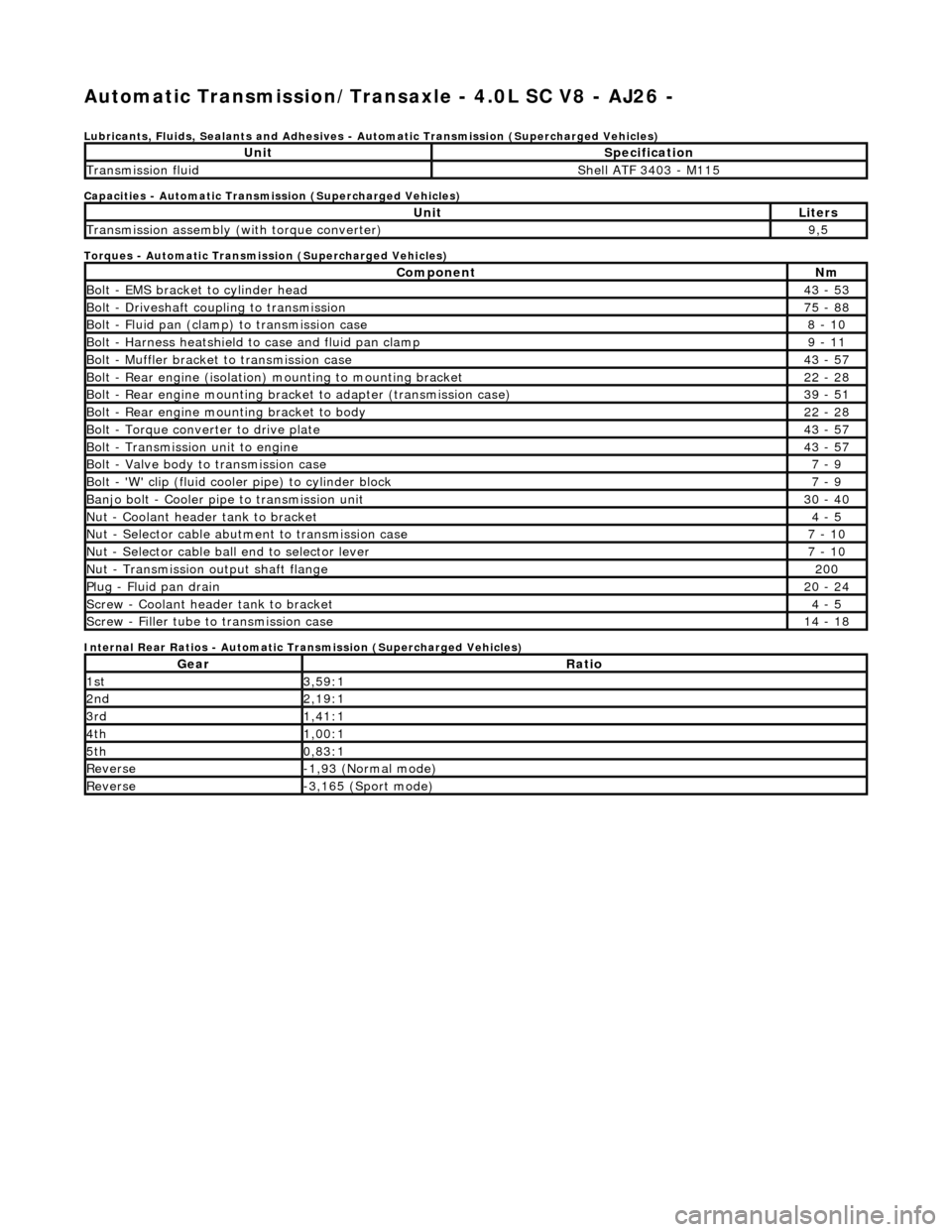
Automatic Transmission/Transaxle - 4.0L SC V8 - AJ26 -
Lubricants, Fluids, Sealants and Adhesives - Automatic Transmission (Supercharged Vehicles)
Capacities - Automatic Transmission (Supercharged Vehicles)
Torques - Automatic Transmission (Supercharged Vehicles)
Internal Rear Ratios - Automatic Transmission (Supercharged Vehicles)
UnitSpecification
Transmission fluidShell ATF 3403 - M115
UnitLiters
Transmission assembly (with torque converter)9,5
ComponentNm
Bolt - EMS bracket to cylinder head43 - 53
Bolt - Driveshaft coupling to transmission75 - 88
Bolt - Fluid pan (clamp) to transmission case8 - 10
Bolt - Harness heatshield to case and fluid pan clamp9 - 11
Bolt - Muffler bracket to transmission case43 - 57
Bolt - Rear engine (isolation) mounting to mounting bracket22 - 28
Bolt - Rear engine mounting brac ket to adapter (transmission case)39 - 51
Bolt - Rear engine mounting bracket to body22 - 28
Bolt - Torque converter to drive plate43 - 57
Bolt - Transmission unit to engine43 - 57
Bolt - Valve body to transmission case7 - 9
Bolt - 'W' clip (fluid cooler pipe) to cylinder block7 - 9
Banjo bolt - Cooler pipe to transmission unit30 - 40
Nut - Coolant header tank to bracket4 - 5
Nut - Selector cable abutment to transmission case7 - 10
Nut - Selector cable ball end to selector lever7 - 10
Nut - Transmission output shaft flange200
Plug - Fluid pan drain20 - 24
Screw - Coolant header tank to bracket4 - 5
Screw - Filler tube to transmission case14 - 18
GearRatio
1st3,59:1
2nd2,19:1
3rd1,41:1
4th1,00:1
5th0,83:1
Reverse-1,93 (Normal mode)
Reverse-3,165 (Sport mode)
Page 1389 of 2490
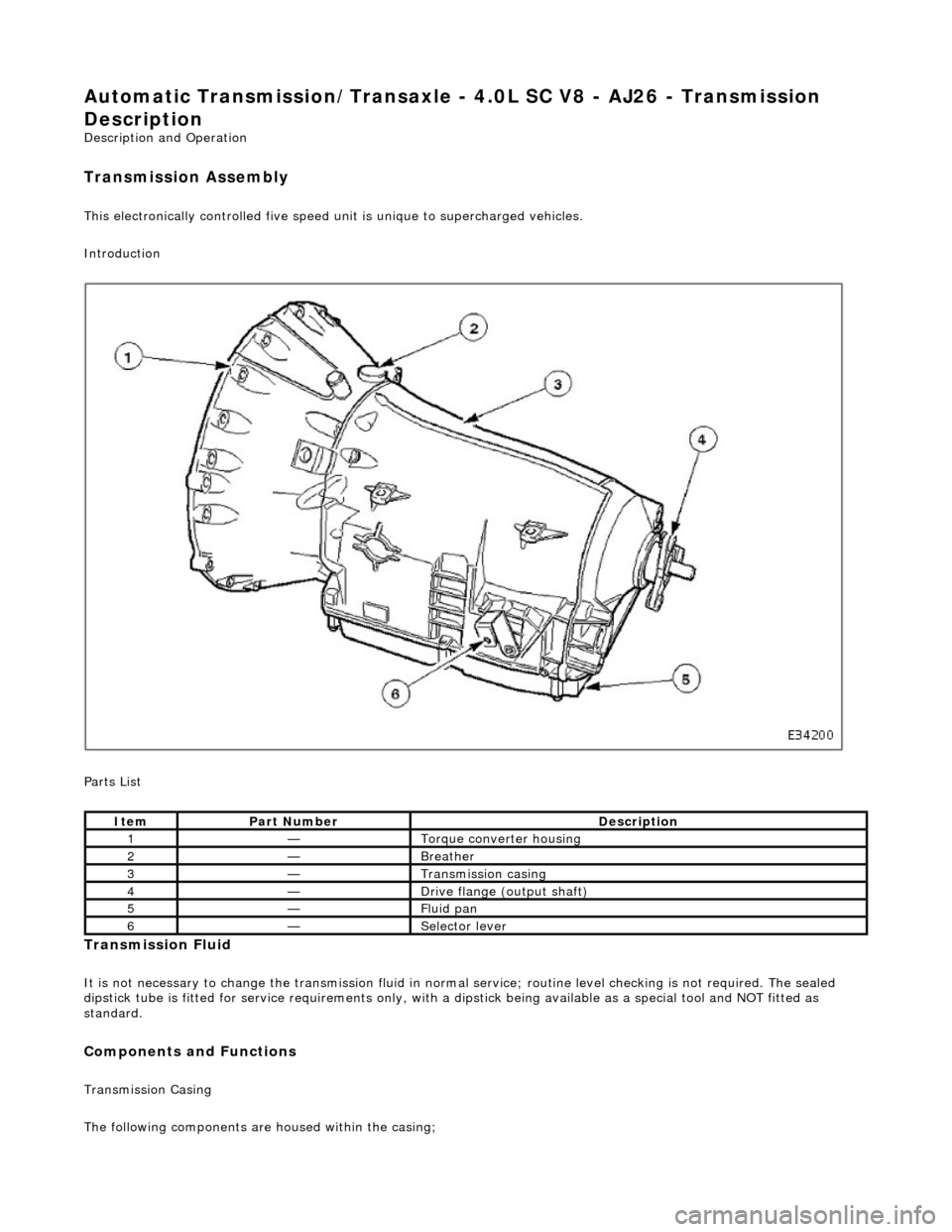
Automatic Transmission/Transaxle - 4.0L SC V8 - AJ26 - Transmission
Description
Description and Operation
Transmission Assembly
This electronically controlled five speed unit is unique to supercharged vehicles.
Introduction
Parts List
Transmission Fluid
It is not necessary to change the transmis sion fluid in normal service; routine level checking is not required. The sealed
dipstick tube is fitted for service requir ements only, with a dipstick being availa ble as a special tool and NOT fitted as
standard.
Components and Functions
Transmission Casing
The following components are housed within the casing;
ItemPart NumberDescription
1—Torque converter housing
2—Breather
3—Transmission casing
4—Drive flange (output shaft)
5—Fluid pan
6—Selector lever
Page 1392 of 2490
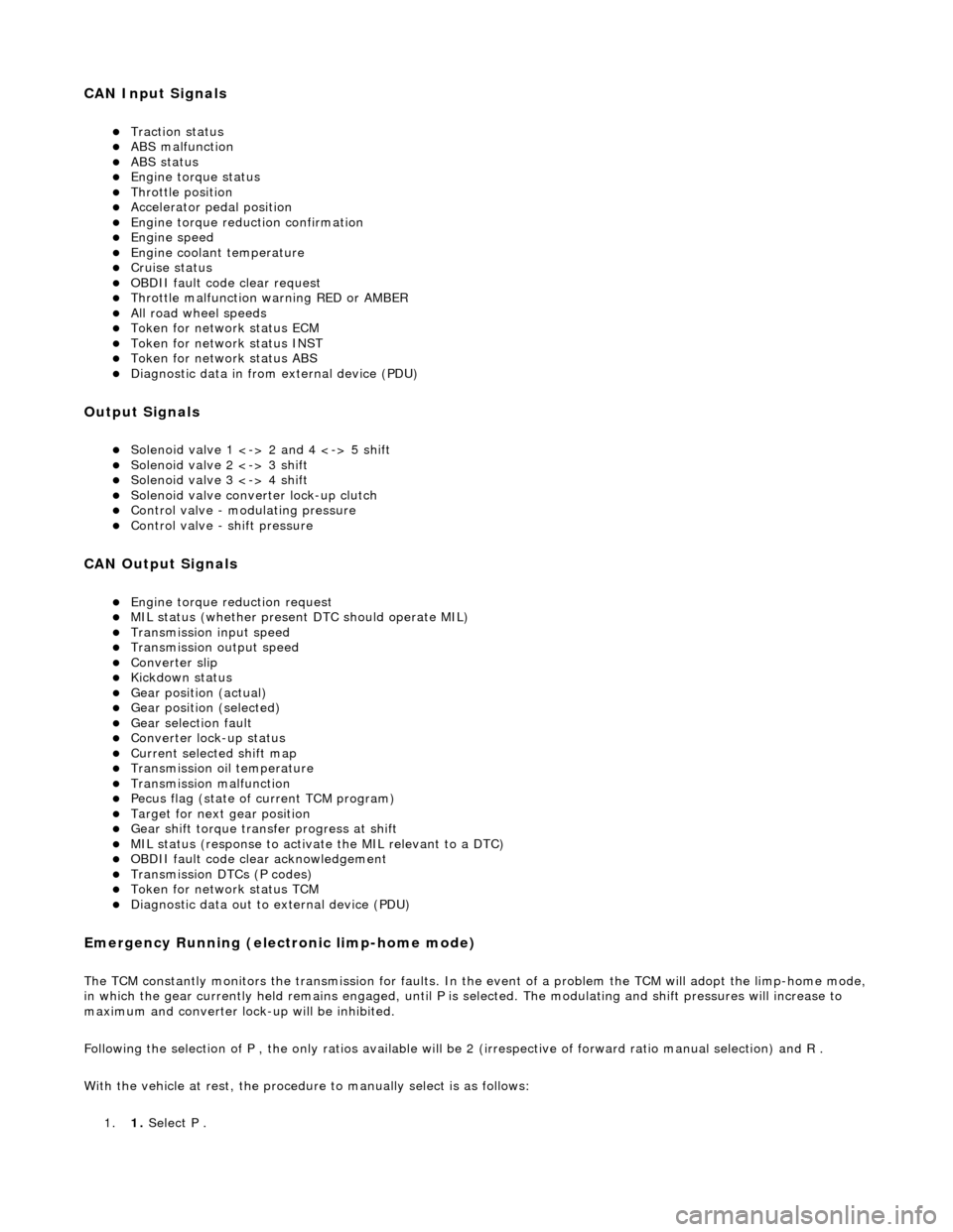
CAN Input Signals
пЃ¬Traction status пЃ¬ABS malfunction пЃ¬ABS status пЃ¬Engine torque status пЃ¬Throttle position пЃ¬Accelerator pedal position пЃ¬Engine torque reduction confirmation пЃ¬Engine speed пЃ¬Engine coolant temperature пЃ¬Cruise status пЃ¬OBDII fault code clear request пЃ¬Throttle malfunction warning RED or AMBER пЃ¬All road wheel speeds пЃ¬Token for network status ECM пЃ¬Token for network status INST пЃ¬Token for network status ABS пЃ¬Diagnostic data in from external device (PDU)
Output Signals
пЃ¬Solenoid valve 1 <-> 2 and 4 <-> 5 shift пЃ¬Solenoid valve 2 <-> 3 shift пЃ¬Solenoid valve 3 <-> 4 shift пЃ¬Solenoid valve converter lock-up clutch пЃ¬Control valve - modulating pressure пЃ¬Control valve - shift pressure
CAN Output Signals
пЃ¬Engine torque reduction request пЃ¬MIL status (whether present DTC should operate MIL) пЃ¬Transmission input speed пЃ¬Transmission output speed пЃ¬Converter slip пЃ¬Kickdown status пЃ¬Gear position (actual) пЃ¬Gear position (selected) пЃ¬Gear selection fault пЃ¬Converter lock-up status пЃ¬Current selected shift map пЃ¬Transmission oil temperature пЃ¬Transmission malfunction пЃ¬Pecus flag (state of current TCM program) пЃ¬Target for next gear position пЃ¬Gear shift torque transfer progress at shift пЃ¬MIL status (response to activate the MIL relevant to a DTC) пЃ¬OBDII fault code clear acknowledgement пЃ¬Transmission DTCs (P codes) пЃ¬Token for network status TCM пЃ¬Diagnostic data out to external device (PDU)
Emergency Running (elect ronic limp-home mode)
The TCM constantly monitors the transmissi on for faults. In the event of a problem the TCM will adopt the limp-home mode, in which the gear currently held remains engaged, until P is selected. The modulati ng and shift pressures will increase to
maximum and converter lock-up will be inhibited.
Following the selection of P , the only ratios available will be 2 (irrespective of forward ratio manual selection) and R .
With the vehicle at rest, the procedure to manually select is as follows:
1. 1. Select P .
Page 1397 of 2490
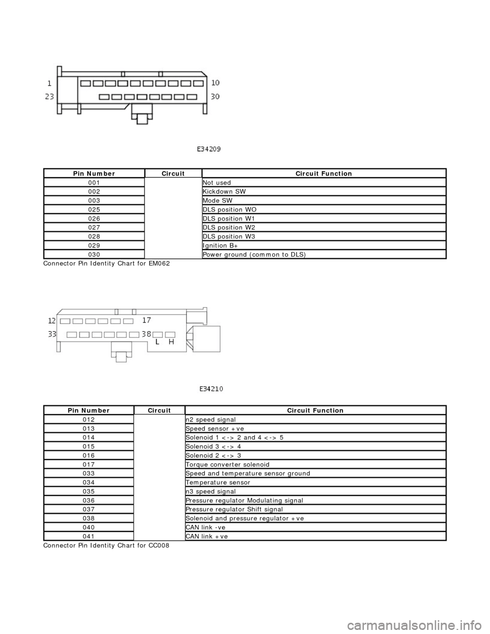
Connector Pin Identity Chart for EM062
Connector Pin Identity Chart for CC008
Pin NumberCircuitCircuit Function
001Not used
002Kickdown SW
003Mode SW
025DLS position WO
026DLS position W1
027DLS position W2
028DLS position W3
029Ignition B+
030Power ground (common to DLS)
Pin NumberCircuitCircuit Function
012n2 speed signal
013Speed sensor +ve
014Solenoid 1 <-> 2 and 4 <-> 5
015Solenoid 3 <-> 4
016Solenoid 2 <-> 3
017Torque converter solenoid
033Speed and temperature sensor ground
034Temperature sensor
035n3 speed signal
036Pressure regulator Modulating signal
037Pressure regulator Shift signal
038Solenoid and pressure regulator +ve
040CAN link -ve
041CAN link +ve