JAGUAR X308 1998 2.G Workshop Manual
X308 1998 2.G
JAGUAR
JAGUAR
https://www.carmanualsonline.info/img/21/7640/w960_7640-0.png
JAGUAR X308 1998 2.G Workshop Manual
Page 1466 of 2490
пЃ¬Is hard-wired to the transmission control module.
Kickdown Switch (where fitted)
The kickdown switch:
пЃ¬Is floor mounted under the accelerator pedal. пЃ¬Is operated by pressing the pedal to the full throttle position. пЃ¬Provides maximum acceleration on driver demand, by signal ling the transmission control module to select the lowest gear to give maximum wheel torque.
Transmission Unit Gear Selector
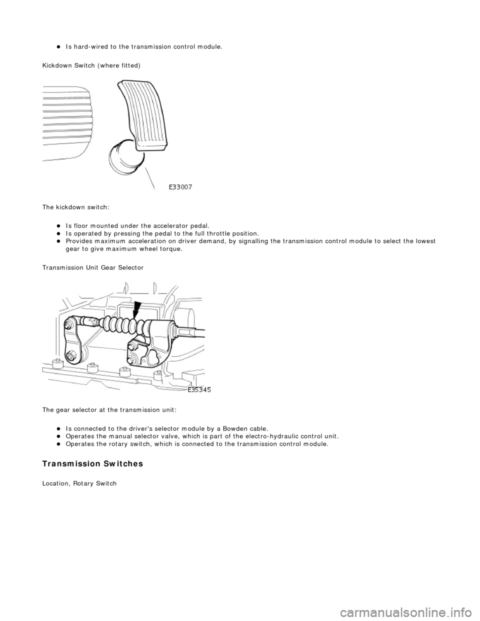
The gear selector at the transmission unit:
пЃ¬Is connected to the driver's selector module by a Bowden cable. пЃ¬Operates the manual selector valve, which is part of the electro-hydraulic control unit. пЃ¬Operates the rotary switch, which is connected to the transmission control module.
Transmission Switches
Location, Rotary Switch
Page 1483 of 2490
moving the set position of either the shift lever or the selector lever.
3. Tighten the locknuts to the specified torque figure
4. Verify the N setting.
11. Further installation is the reve rse of the removal procedure.
12. Connect the battery and fit the battery cover.
пЃ¬Reset the radio and the clock.
Page 1488 of 2490
Installation
12. Push the outer cable grommet through the transmission
tunnel aperture.
13. Remove the selector cable assembly from the vehicle.
1. Assemble the cable to the gear shift assembly.
1. Locate the outer cable.
2. Fit and tighten the cable securing nut to the specified torque figure.
2. Connect the selector cable to the transmission.
1. Fit the bolts which secure the cable to the transmission casing and tighten to the specified
torque figure.
Page 1489 of 2490
2. Fit and tighten the inner cable securing nut to the
specified torque figure.
3. Secure the outer cable.
4. Adjust the selector cable in accordance with 44.15.07.
5. Further installation is the reve rse of the removal procedure.
Page 1494 of 2490
Automatic Transmission/Transaxle External Controls - 4.0L NA V8 -
AJ27/3.2L NA V8 - AJ26 - Selector Lever Knob
Removal and Installation
Removal
Installation
1. Remove the select or lever knob.
1. Slacken the ferrule, rotate clock-wise.
2. Rotate the knob coun ter-clockwise to remove.
1. Refer to the illustration
1. Fit the knob.
2. Tighten the ferru le to the specified torque figure.
Page 1498 of 2490
19. Inst
all the slide plate.
пЃ¬Install
the four sl
ide plate screws.
20 . Fi
t the gear shift assembly.
пЃ¬Inst
all th
e four nuts.
21 . Asse
mble the cable to the gear shift assembly.
1. Locate the outer cable.
2. Fit and tighten the cable securing nut to the specified torque figure.
22. Adjust, or verify, the cable in accordance with 44.15.07.
23. Further installation is the reve rse of the removal procedure.
24. Connect the battery and fit the battery cover.
пЃ¬Reset the radio an
d the clock.
Page 1502 of 2490

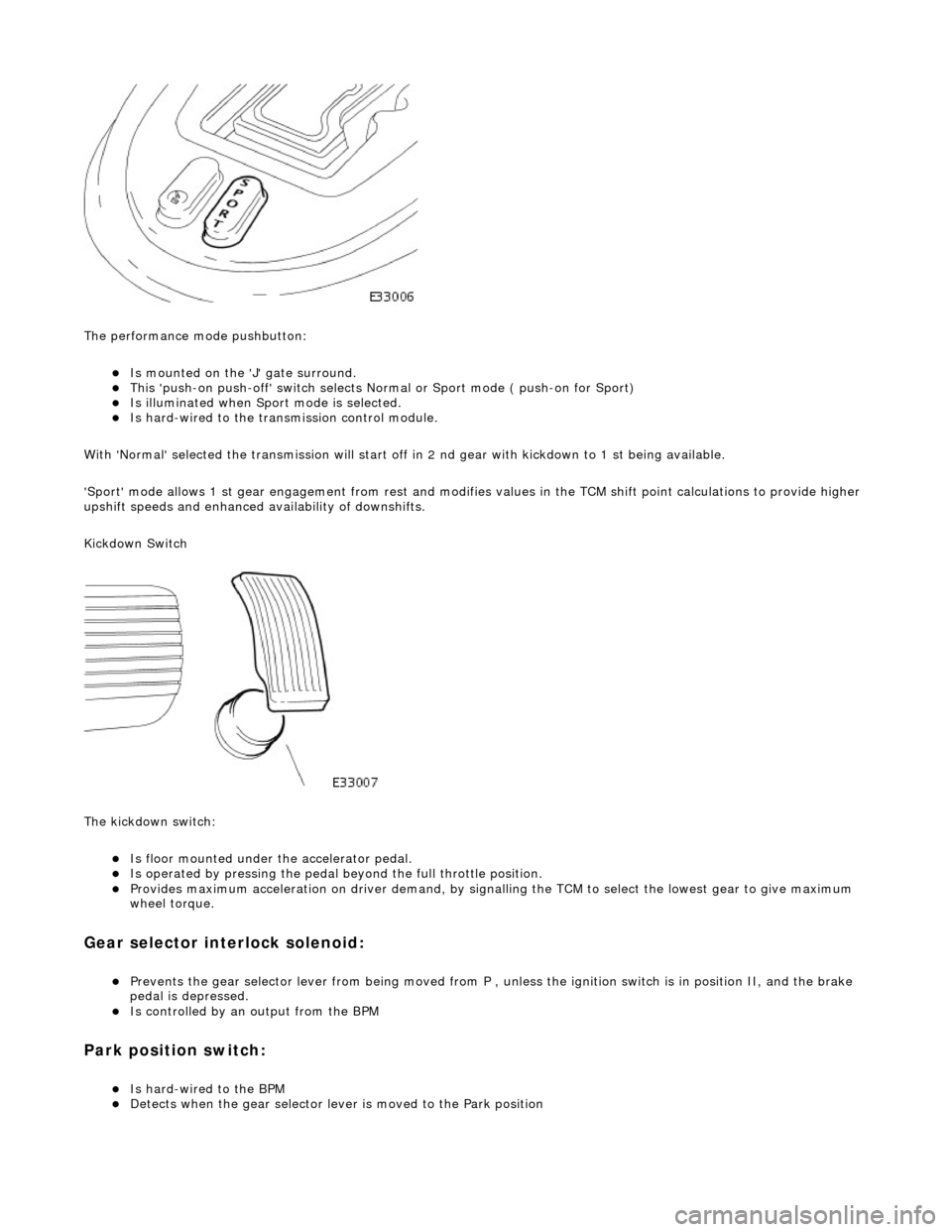
The performance mode pushbutton:
пЃ¬Is mounted on the 'J' gate surround. пЃ¬This 'push-on push-off' swit ch selects Normal or Sport mode ( push-on for Sport) пЃ¬Is illuminated when Sport mode is selected. пЃ¬Is hard-wired to the transmission control module.
With 'Normal' selected the transmissi on will start off in 2 nd gear with kickdown to 1 st being available.
'Sport' mode allows 1 st gear en gagement from rest and modifies values in the TCM shift point calculations to provide higher
upshift speeds and enhanced availability of downshifts.
Kickdown Switch
The kickdown switch:
пЃ¬Is floor mounted under th e accelerator pedal. пЃ¬Is operated by pressing the pedal beyond the full throttle position. пЃ¬Provides maximum acceleration on driver demand, by signalling the TCM to select the lowest gear to give maximum
wheel torque.
Gear selector interlock solenoid:
пЃ¬Prevents the gear selector lever from being moved from P , unless the ignition switch is in position II, and the brake
pedal is depressed.
пЃ¬Is controlled by an output from the BPM
Park position switch:
пЃ¬Is hard-wired to the BPM пЃ¬Detects when the gear selector lever is moved to the Park position
Page 1514 of 2490
Installation
2. Slacken the outer cable locknuts.
13. Push the outer cable grommet through the transmission
tunnel aperture.
14. Remove the selector cable assembly from the vehicle.
1. Assemble the cable to the gear shift assembly.
1. Locate the outer cable and fit the inner cable to the gear selector arm. Tighten to the specified torque
figure.
2. Position the abutment nuts to the approximate position, but do not tighten.
2. Fit the cable to the transmission and tighten the fixings to the
specified torque figure.
Page 1522 of 2490
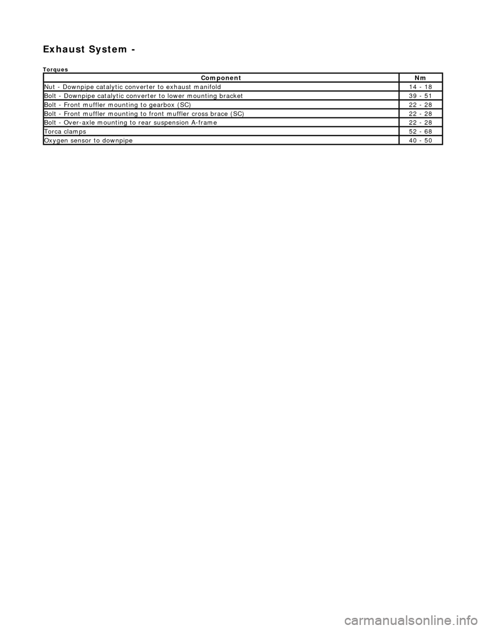
Exhaust System -
Torques
ComponentNm
Nut - Downpipe catalytic converter to exhaust manifold14 - 18
Bolt - Downpipe catalytic converter to lower mounting bracket39 - 51
Bolt - Front muffler mounting to gearbox (SC)22 - 28
Bolt - Front muffler mounting to front muffler cross brace (SC)22 - 28
Bolt - Over-axle mounting to rear suspension A-frame22 - 28
Torca clamps52 - 68
Oxygen sensor to downpipe40 - 50
Page 1525 of 2490
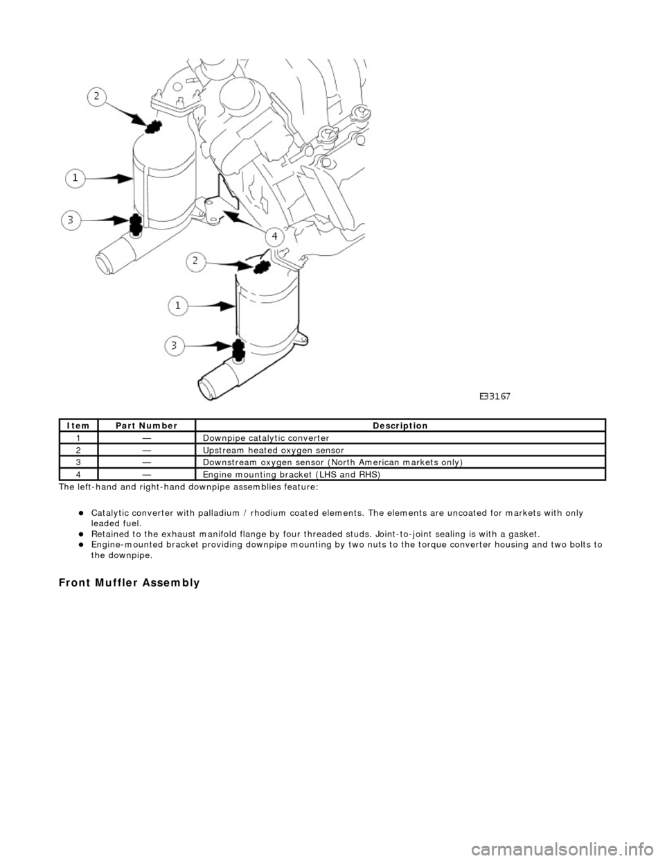
The left-hand and right-hand do wnpipe assemblies feature:
пЃ¬Catalytic converter with palladium / rhodium coated elem ents. The elements are uncoated for markets with only
leaded fuel.
пЃ¬Retained to the exhaust manifold flange by four thread ed studs. Joint-to-joint sealing is with a gasket. пЃ¬Engine-mounted bracket providing downpipe mounting by two nuts to the torque converter housing and two bolts to
the downpipe.
Front Muffler Assembly
ItemPart NumberDescription
1—Downpipe catalytic converter
2—Upstream heated oxygen sensor
3—Downstream oxygen sensor (North American markets only)
4—Engine mounting bracket (LHS and RHS)


