torque JAGUAR X308 1998 2.G Workshop Manual
[x] Cancel search | Manufacturer: JAGUAR, Model Year: 1998, Model line: X308, Model: JAGUAR X308 1998 2.GPages: 2490, PDF Size: 69.81 MB
Page 1738 of 2490
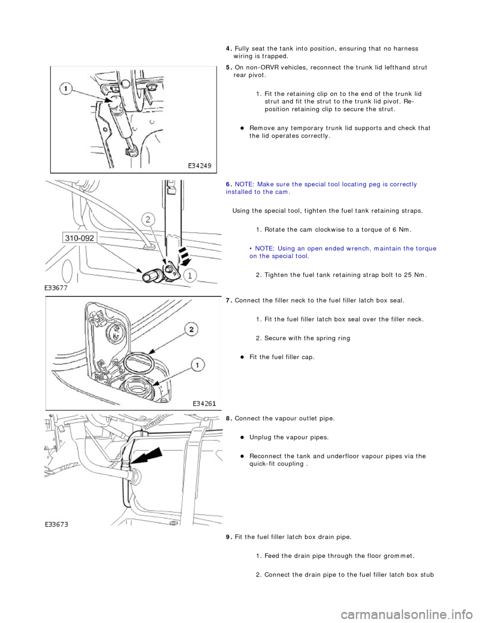
4. Full
y seat the tank into positi
on, ensuring that no harness
wiring is trapped.
5. On non-
ORVR vehicles, reconnec
t the trunk lid lefthand strut
rear pivot.
1. Fit the retaining clip on to the end of the trunk lid strut and fit the strut to the trunk lid pivot. Re-
position retaining clip to secure the strut.
пЃ¬Re
move any temporary trunk lid supports and check that
the lid operates correctly.
6. NOTE
: Make sure the special tool locating peg is correctly
installed to the cam.
Using the special tool, tighten the fuel tank retaining straps.
1. Rotate the cam clockwise to a torque of 6 Nm.
• NOTE: Using an open ended wrench, maintain the torque
on the special tool.
2. Tighten the fuel tank reta ining strap bolt to 25 Nm.
7. Connect the fi
ller neck to the fuel filler latch box seal.
1. Fit the fuel filler latch box seal over the filler neck.
2. Secure with the spring ring
пЃ¬F i
t the fuel filler cap.
8. Connect the vapour outlet pip
e.
пЃ¬Unplug the v
a
pour pipes.
пЃ¬Reconn
ect th
e tank and underfloor vapour pipes via the
quick-fit coupling .
9. Fit the fuel filler latch box drain pipe.
1. Feed the drain pipe th rough the floor grommet.
2. Connect the drain pipe to the fuel filler latch box stub
Page 1754 of 2490
WARNING: NEVER USE A CFC 12 ANALYZ
ER OR NAKED FLAME TYPE.
Leak tests should be carried out with a UV spot lamp or an electronic analyzer which is dedicated to HFC 134A refrigerant.
Handling Lubricati
ng Oil
Av
oid breathing lubricant mist; it can cau
s
e irritation to the respiratory system.
Always use fresh oil from a sealed containe r and do not leave oil exposed to the atmosphere for any reason other than to fill
or empty a system. PAG oil is very hygr oscopic (absorbs water) and will rapidly become contaminated by atmospheric
moisture.
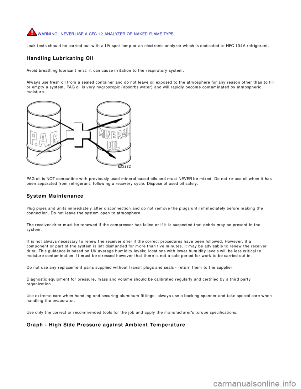
PAG oil is NOT compatible with previously used mineral based oi ls and must NEVER be mixed. Do not re-use oil when it has
been separated from refrigerant, following a re covery cycle. Dispose of used oil safely.
System Maintenance
Plug pipes an
d units immediatel
y after disconnection an d do not remove the plugs until immediately before making the
connection. Do not leave the system open to atmosphere.
The receiver drier must be renewed if the compressor has failed or if it is susp ected that debris may be present in the
system.
It is not always necessary to renew th e receiver drier if the correct procedur es have been followed. However, if a
component or part of the system is left dismantled for more than five minutes, it may be advisable to renew the receiver
drier. This guidance is based on UK average humidity levels; lo cations with lower humidity levels will be less critical to
moisture contamination. It must be stressed however th at there is not a safe period for work to be carried out in.
Do not use any replacement parts su pplied without transit plugs and seals - return them to the supplier.
Diagnostic equipment for pres sure, mass and volume should be calibrated regularly and certified by a third party
organization.
Use extreme care when handling and securi ng aluminum fittings; always use a backing spanner and take special care when
handling the evaporator.
Use only the correct or re commended tools for the job and apply the manufacturer's torque specifications.
Graph - High S
ide Pressure against Ambient Temperature
Page 1756 of 2490
Probable
causes of faults may be found by comparing actual
system pressures, registered on your manifold gauge set or
recovery / recharge / recycle station, and the relevant pressure to temperature relationship graph. The following chart
shows the interpretation that ma y be made by this difference.
• NOTE: The A/CCM will disengage the compressor clutch should the evaporator temperature fall to 0°C.
• NOTE: Graphs are typical for HFC 134A
The 'Normal' condition is that which is relevant to the prevailing evaporator temperature.
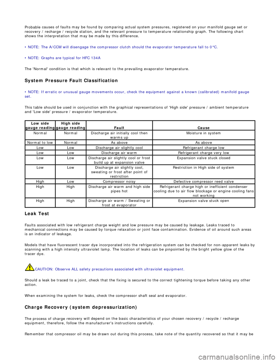
System Pressure Fault Classification
• NOTE
: If erratic or unusual gauge move
ments occur, check the equipment against a known (calibrated) manifold gauge
set.
This table should be used in conjunction with the graphical representations of 'High side' pressure / ambient temperature
and 'Low side' pressure / evaporator temperature.
Leak
Test
F
a
ults associated with low re
frigerant charge weight and low pressure ma y be caused by leakage. Leaks traced to
mechanical connections may be caused by to rque relaxation or joint face contamination. Evidence of oil around such areas
is an indicator of leakage.
Models that have fluorescent tracer dye incorporated into the refrigeration system can be checke d for non-apparent leaks by
scanning with a high intensity ultraviolet lamp. The location of leaks can be pinpointed by the bright yellow glow of the
tracer dye.
CAUTION: Observe ALL safety precautions associated with ultraviolet equipment.
Should a leak be traced to a joint, check that the fixing is secured to the correct tightening torque before taking any other
action.
When examining the system for leaks, chec k the compressor shaft seal and evaporator.
Charge Re
covery (system depressurization)
The process of
charge r
ecovery will depe
nd on the basic characteristics of your chosen recovery / recycle / recharge
equipment, therefore, follow the manu facturer's instructions carefully.
Remember that compressor oil may be drawn out during this process, take note of the quantity recovered so that it may be
Lo
w side
gauge reading
High s i
de
gauge reading
Fau l
t
Cause
No
r
mal
No
r
mal
Di
sc
harge air initially cool then
warms up
Mois
ture in system
N
ormal
to low
No
r
mal
As aboveAs above
LowLowD
i
scharge air slightly cool
Ref
r
igerant charge low
LowLowDi
scharge air warm
Refr
igerant charge very low
LowLowDi
scharge air slightly cool or frost
build up at expansion valve
Expansion valve st
uck closed
LowLowDi
scharge air slightly cool,
sweating or frost after point of restriction
Restri
ction in High side of system
HighLowCompressor noisyDe
fe
ctive compressor reed valve
HighHighD
i
scharge air warm and high side
pipes hot
Refri
gerant charge high or inefficient condenser
cooling due to air flow blockage or engine cooling fans
not working
HighHighD i
scharge air warm / Sweating or
frost at evaporator
Expans ion valve st
uck open
Page 1918 of 2490
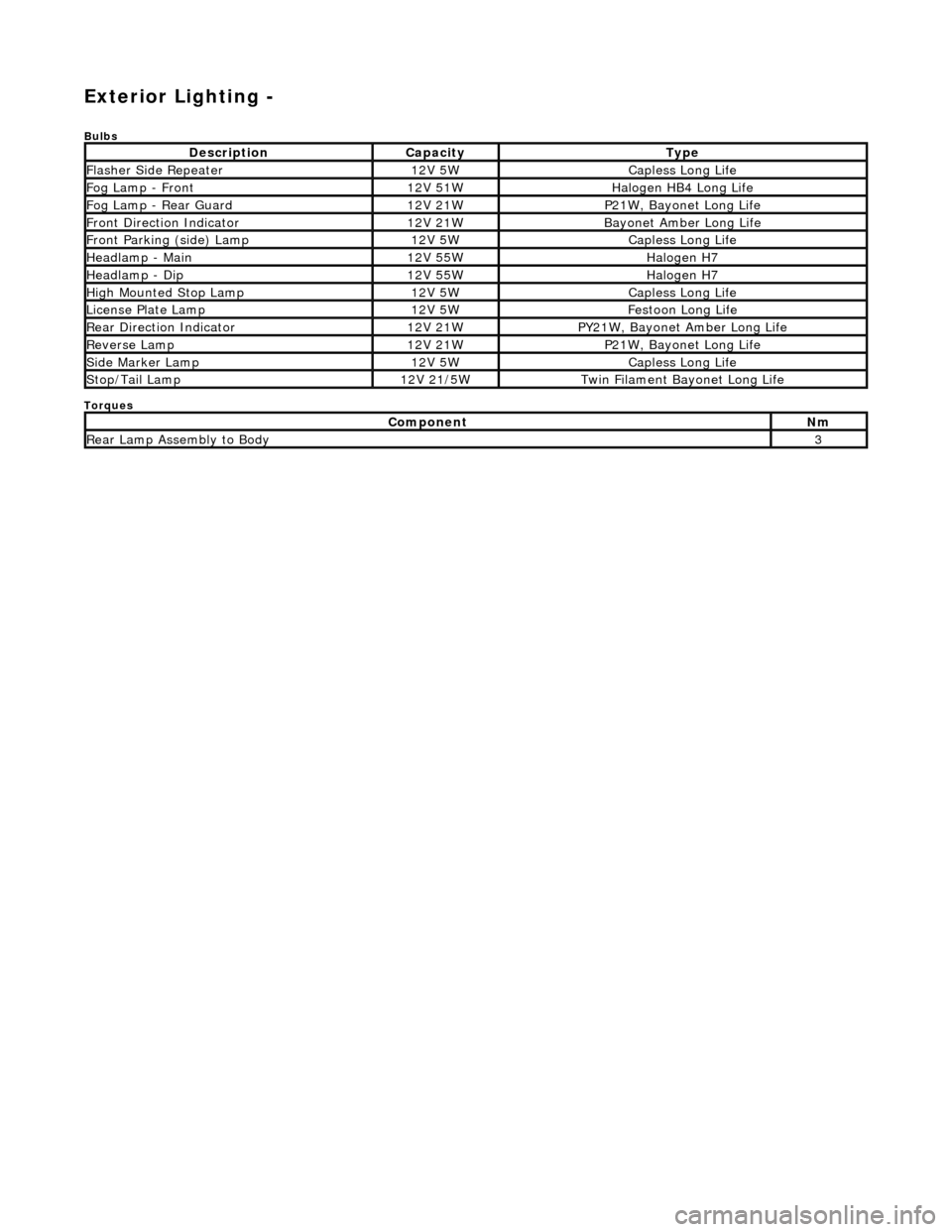
Exterior Lighting -
Bulbs
Torques
DescriptionCapacityType
Flasher Side Repeater12V 5WCapless Long Life
Fog Lamp - Front12V 51WHalogen HB4 Long Life
Fog Lamp - Rear Guard12V 21WP21W, Bayonet Long Life
Front Direction Indicator12V 21WBayonet Amber Long Life
Front Parking (side) Lamp12V 5WCapless Long Life
Headlamp - Main12V 55WHalogen H7
Headlamp - Dip12V 55WHalogen H7
High Mounted Stop Lamp12V 5WCapless Long Life
License Plate Lamp12V 5WFestoon Long Life
Rear Direction Indicator12V 21WPY21W, Bayonet Amber Long Life
Reverse Lamp12V 21WP21W, Bayonet Long Life
Side Marker Lamp12V 5WCapless Long Life
Stop/Tail Lamp12V 21/5WTwin Filament Bayonet Long Life
ComponentNm
Rear Lamp Assembly to Body3
Page 2019 of 2490
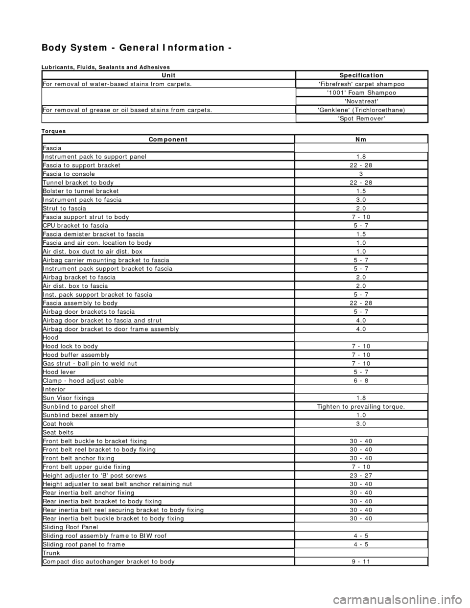
Body System - General Information -
Lubricants, Fluids, Sealants and Adhesives
Torques
UnitSpecification
For removal of water-based stains from carpets.'Fibrefresh' carpet shampoo
'1001' Foam Shampoo
'Novatreat'
For removal of grease or oil based stains from carpets.'Genklene' (Trichloroethane)
'Spot Remover'
ComponentNm
Fascia
Instrument pack to support panel1.8
Fascia to support bracket22 - 28
Fascia to console3
Tunnel bracket to body22 - 28
Bolster to tunnel bracket1.5
Instrument pack to fascia3.0
Strut to fascia2.0
Fascia support strut to body7 - 10
CPU bracket to fascia5 - 7
Fascia demister bracket to fascia1.5
Fascia and air con. location to body1.0
Air dist. box duct to air dist. box1.0
Airbag carrier mounting bracket to fascia5 - 7
Instrument pack suppo rt bracket to fascia5 - 7
Airbag bracket to fascia2.0
Air dist. box to fascia2.0
Inst. pack support bracket to fascia5 - 7
Fascia assembly to body22 - 28
Airbag door brackets to fascia5 - 7
Airbag door bracket to fascia and strut4.0
Airbag door bracket to door frame assembly4.0
Hood
Hood lock to body7 - 10
Hood buffer assembly7 - 10
Gas strut - ball pin to weld nut7 - 10
Hood lever5 - 7
Clamp - hood adjust cable6 - 8
Interior
Sun Visor fixings1.8
Sunblind to parcel shelfTighten to prevailing torque.
Sunblind bezel assembly1.0
Coat hook3.0
Seat belts
Front belt buckle to bracket fixing30 - 40
Front belt reel bracket to body fixing30 - 40
Front belt anchor fixing30 - 40
Front belt upper guide fixing7 - 10
Height adjuster to 'B' post screws23 - 27
Height adjuster to seat belt anchor retaining nut30 - 40
Rear inertia belt anchor fixing30 - 40
Rear inertia belt bracket to body fixing30 - 40
Rear inertia belt reel secu ring bracket to body fixing30 - 40
Rear inertia belt buckle bracket to body fixing30 - 40
Sliding Roof Panel
Sliding roof assembly frame to BIW roof4 - 5
Sliding roof panel to frame4 - 5
Trunk
Compact disc autochanger bracket to body9 - 11
Page 2343 of 2490
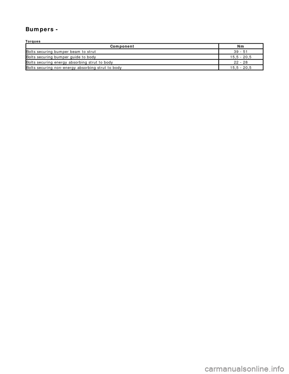
Bumpers -
Torques
ComponentNm
Bolts securing bumper beam to strut39 - 51
Bolts securing bumper guide to body15,5 - 20,5
Bolts securing energy absorbing strut to body22 - 28
Bolts securing non-energy absorbing strut to body15,5 - 20,5
Page 2359 of 2490
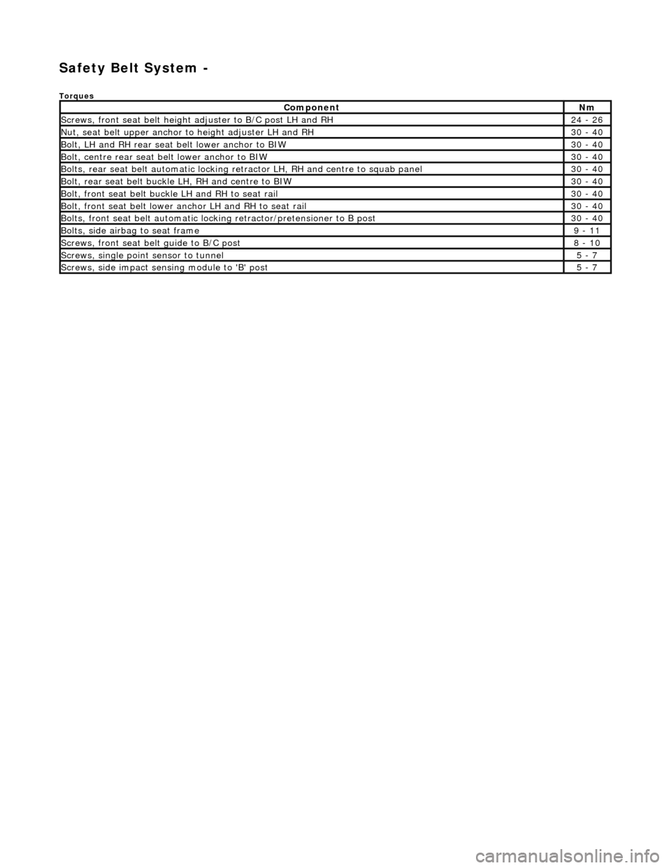
Safety Belt System -
Torques
ComponentNm
Screws, front seat belt height adjuster to B/C post LH and RH24 - 26
Nut, seat belt upper anchor to height adjuster LH and RH30 - 40
Bolt, LH and RH rear seat belt lower anchor to BIW30 - 40
Bolt, centre rear seat belt lower anchor to BIW30 - 40
Bolts, rear seat belt automatic locking re tractor LH, RH and centre to squab panel30 - 40
Bolt, rear seat belt buckle LH, RH and centre to BIW30 - 40
Bolt, front seat belt buckle LH and RH to seat rail30 - 40
Bolt, front seat belt lower an chor LH and RH to seat rail30 - 40
Bolts, front seat belt automatic lock ing retractor/pretensioner to B post30 - 40
Bolts, side airbag to seat frame9 - 11
Screws, front seat belt guide to B/C post8 - 10
Screws, single point sensor to tunnel5 - 7
Screws, side impact sens ing module to 'B' post5 - 7
Page 2368 of 2490
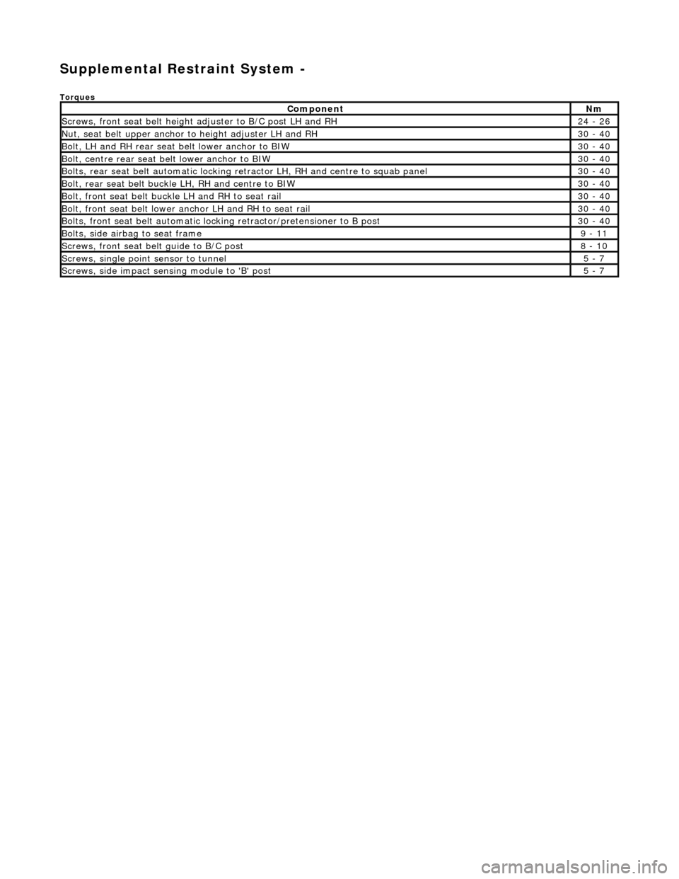
Supplemental Restraint System -
Torques
ComponentNm
Screws, front seat belt height adjuster to B/C post LH and RH24 - 26
Nut, seat belt upper anchor to height adjuster LH and RH30 - 40
Bolt, LH and RH rear seat belt lower anchor to BIW30 - 40
Bolt, centre rear seat belt lower anchor to BIW30 - 40
Bolts, rear seat belt automatic locking re tractor LH, RH and centre to squab panel30 - 40
Bolt, rear seat belt buckle LH, RH and centre to BIW30 - 40
Bolt, front seat belt buckle LH and RH to seat rail30 - 40
Bolt, front seat belt lower an chor LH and RH to seat rail30 - 40
Bolts, front seat belt automatic lock ing retractor/pretensioner to B post30 - 40
Bolts, side airbag to seat frame9 - 11
Screws, front seat belt guide to B/C post8 - 10
Screws, single point sensor to tunnel5 - 7
Screws, side impact sens ing module to 'B' post5 - 7