torque JAGUAR X308 1998 2.G Manual Online
[x] Cancel search | Manufacturer: JAGUAR, Model Year: 1998, Model line: X308, Model: JAGUAR X308 1998 2.GPages: 2490, PDF Size: 69.81 MB
Page 1054 of 2490

Accessory Drive - Accessory Drive Belt
4.0L SC V8 - AJ26
Re
mo
val and Installation
Remov
a
l
Installation
1.
Op
en the engine compartment and fit paintwork protection
sheets.
2. Remove the supercharger driv e belt, for access. Refer to
operation 18.50.08.
3. Check the belt wear indicator ma rks to confirm that the drive
belt is / is not within limits.
4. CAUTIO
N: When releasing the
belt tension, never apply
any torque in a clockwise direction to the pulley ce ntre bolt (left
hand thread) as it could subsequently loosen.
Remove the drive belt fro m the accessory drive.
1. Use a spanner e.g. Churchill JD-230 or Snap On XDHM 1415, on the centre bo lt of the belt tensioner
idler pulley, to turn the adju ster assembly to the left,
viewed from the front, against spring tension.
2. Whilst holding the tensioner against spring tension, remove the drive belt from the generator pulley.
Release the tensioner sl owly and remove the
spanner.
пЃ¬D i
sconnect the belt from the ot
her pulleys, as necessary.
1. Ins
tallation is the
reverse of the remova l procedure. Ensure
that the belt is correctly and sq uarely located on each pulley.
2. Refit the supercharger drive belt. Refer to operation 18.50.08.
Page 1072 of 2490

Engine Ignition -
General Spe
cifications
Torque Specifications
Ite
m / Model
Sp
ecification
F
i
ring Order (cylinder - bank)
1-
1
, 1-2, 4-1, 2-1, 2-2, 3-1, 3-2, 4-2
Spark P
l
ug Type
(Leaded markets -
service fit only)NGK BK
R5E-11
N
ormal
ly Aspirated
NG
K PF
R5G-11E
SuperchargedNG
K PF
R6G-13E
Spark P
l
ug Gap
mm
(i
n)
(Leaded markets -
service fit only)1.0 -
1.1 (0.039 - 0.043)
N
ormal
ly Aspirated
1.
0 -
1.1 (0.039 - 0.043)
Supercharged1.
2 -
1.3 (0.047 - 0.051)
High
Tem
perature Nickel Anti-Seize
Lubricant (Spark Plug Thread)
'Ne
verseez' (ESE-M12A4-A)
Com
p
onent
Nm
Spark P
l
ugs
25
-
29
Coil
on
Plug Bolts
4 -
6
Co
il
Cover Bolts
4 -
6
Page 1083 of 2490
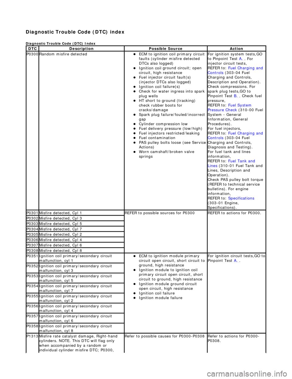
Diagnostic Trouble Code (D
TC) index
D
iagnostic Trouble Code (DTC) Index
DT
C
De
scription
Possib
le Source
Acti
on
P0300Ran
dom misfire detected
пЃ¬ECM t
o ignition coil primary circuit
faults (cylinder misfire detected
DTCs also logged)
пЃ¬Ignition coil
ground circuit; open
circuit, high resistance
пЃ¬F
uel injector circuit fault(s)
(injector DTCs also logged)
пЃ¬Ignition coil
failure(s)
пЃ¬Check f
or water ingress into spark
plug wells
пЃ¬HT sho
rt to ground (tracking)
check rubber boots for
cracks/damage
пЃ¬Spark plug
failure/fouled/incorrect
gap
пЃ¬Cy
linder compression low
пЃ¬F
uel delivery pressure (low/high)
пЃ¬F
uel injectors restricted/leaking
пЃ¬Fuel contamination
пЃ¬P
AS pulley bolts loose (see Service
Actions)
пЃ¬W
orn camshaft/broken valve
springs
For ign
ition system tests,GO
to Pinpoint Test A.
. For
inje
ctor circuit tests,
REFER to: Fuel Charging and
Controls (30
3-04 Fuel
Charging and Controls,
Description and Operation).
Check compressions. For
spark plug tests,GO to
Pinpoint Test B.
.
Check fuel
pressure,
REFER to: Fuel System
Pressure Check (31
0-00 Fuel
System - General
Information, General
Procedures).
For fuel injectors,
REFER to: Fuel Charging and
Controls (30
3-04 Fuel
Charging and Controls,
Diagnosis and Testing).
For fuel tank and lines
information,
REFER to: Fuel Tank and
Lin
es
(310-01 Fuel Tank and
Lines, Description and
Operation).
Check PAS pulley bolt torque
(REFER to technical service
bulletins). For engine
information,
REFER to: Specifications
(3
03-01 Engine,
Specifications).
P0301Misfire
detected, Cyl 1
R
EFER to possible sources for P0300
R
EFER to actions for P0300.
P0302Misfire
detected, Cyl 3
P0303Misfire
detected, Cyl 5
P0304Misfire
detected, Cyl 7
P0305Misfire
detected, Cyl 2
P0306Misfire
detected, Cyl 4
P0307Misfire
detected, Cyl 6
P0308Misfire
detected, Cyl 8
P0351Igni
tion coil primary/secondary circuit
malfunction, cyl 1
пЃ¬ECM to
ignition module primary
circuit open circuit, short circuit to
ground, high resistance
пЃ¬Igni
tion module to ignition coil
primary circuit open circuit, short
circuit to ground, high resistance
пЃ¬Ignition modu
le ground circuit
open circuit, hi gh resistance
пЃ¬Ignition coil
failure
пЃ¬Ignition modul
e failure
F
or ignition circuit tests,GO to
Pinpoint Test A.
.
P0352Igni
tion coil primary/secondary circuit
malfunction, cyl 3
P0353Igni
tion coil primary/secondary circuit
malfunction, cyl 5
P0354Igni
tion coil primary/secondary circuit
malfunction, cyl 7
P0355Igni
tion coil primary/secondary circuit
malfunction, cyl 2
P0356Igni
tion coil primary/secondary circuit
malfunction, cyl 4
P0357Igni
tion coil primary/secondary circuit
malfunction, cyl 6
P0358Igni
tion coil primary/secondary circuit
malfunction, cyl 8
P1313Misfire rate
catalyst damage, Right-hand
cylinders. NOTE. This DTC will flag only
when accompanied by a random or
individual cylinder misfire DTC; P0300,
R
efer to possible causes for P0300-P0308
R
efer to actions for P0300-
P0308.
Page 1093 of 2490

En
gine Emission Control -
Torque Specific
ations
De
scription
Nmlb
-ft
lb
-in
EGR valve tube to EGR valv
e retaining bolts
2115-
Exhaus
t manifold to EGR valve tube retaining bolts
2115-
Exhaus
t manifold to EGR valve tube retaining nuts
2115-
Evaporati
ve emission canister purge valve retaining bolts
6-53
EGR valve to th
rottle body elbow retaining bolts
129-
Page 1106 of 2490
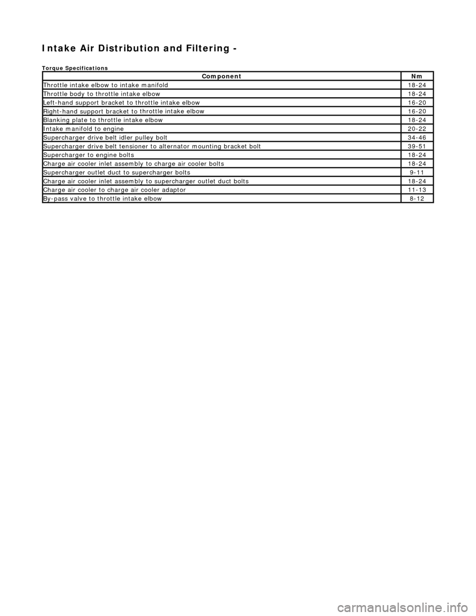
Intake Air Distribution and Filtering -
Torque Specificat
ions
Comp
onent
Nm
Thr
o
ttle intake elbow to intake manifold
18
-
24
Thro
tt
le body to throttle intake elbow
18
-
24
Left-hand support
bracket to
th
rottle intake elbow
16
-
20
Right-hand support
bracket to
throttle intake elbow
16
-
20
B
l
anking plate to throttle intake elbow
18
-
24
Inta
k
e manifold to engine
20
-
22
Supe
rcharger
drive belt idler pulley bolt
34
-
46
Supercharger
drive belt te
nsioner to alternator mounting bracket bolt
39
-
51
Supercharger
to eng
ine bolts
18
-
24
Charge air cooler in
let assembly to charge ai
r cooler bolts
18
-
24
Supercharger
outlet duct to supercharger bolts9-1
1
Charge air cooler in
let assembly to superchar
ger ou
tlet duct bolts
18-
24
Charge air cool
er to charge
air cooler adaptor
11
-
13
B
y
-pass valve to throttle intake elbow
8-
1
2
Page 1113 of 2490
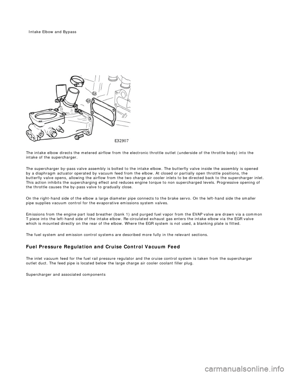
The intake elbow di
rects the metered airflow from the electronic throttle outlet (und
erside of the throttle body) into the
intake of the supercharger.
The supercharger by-pass valve assembly is bolted to the intake elbow. The butterfly valve inside the assembly is opened
by a diaphragm actuator operated by vacu um feed from the elbow. At closed or partially open throttle positions, the
butterfly valve opens, allowing th e airflow from the two charge air cooler inlets to be directed back to the supercharger inlet .
This action inhibits the supercharging e ffect and reduces engine torque to non supercharged levels. Progressive opening of
the throttle causes the by-pass valve to gradually close.
On the right-hand side of the elbow a la rge diameter pipe connects to the brake servo. On the left-hand side the smaller
pipe supplies vacuum control for the evaporative emissions system valves.
Emissions from the engine part load breather (bank 1) and pu rged fuel vapor from the EVAP valve are drawn via a common
T piece into the left-hand side of the intake elbow. Re-cir culated exhaust gas enters the intake elbow via the EGR valve
which is mounted directly on the rear of the elbow. Where the EGR system is not used, a blanking plate is fitted.
The fuel system and emission control systems are described more fully in the relevant sections.
Fuel Pressure Regula
tion and
Cruise Control Vacuum Feed
The inlet v
acuum feed fo
r the fuel rail pressure regula tor and the cruise control system is taken from the supercharger
outlet duct. The feed pipe is located below the large charge air cooler coolant filler plug.
Superchar
ger
and associated components
Inta
ke Elbow and Bypass
Page 1175 of 2490

E
lectronic Engine Controls -
Torque spe
cification
Com
ponent
Nm
Engine
coolant temperature sensor
15
- 19
Camshaft position
sensor
9 -
11
Cranksh
aft position sensor
8 -
12
Knock
sensor
31
- 41
O
xygen sensor to downpipe
40
- 50
Inta
ke air temperature sensor (SC only)
30
- 40
Page 1260 of 2490
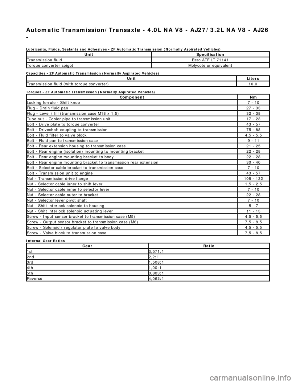
Automatic Transmission/Transaxle - 4.0L NA V8 - AJ27/3.2L NA V8 - AJ26
-
Lubri c
ants, Fluids, Sealants and Adhesives - ZF Au
tomatic Transmission (Normally Aspirated Vehicles)
Capacities - ZF Automatic Transmission (Normally Aspirated Vehicles)
Torques - ZF Automatic Transmission (Normally Aspirated Vehicles)
Internal Gear Ratios
UnitS p
ecification
Transmissi
on fluidEsso
ATF LT 71141
Torque converter spigotMolyc
o
te or equivalent
UnitLi
t
ers
Transmissi
on fluid (with
torque converter)
10
,0
Com p
onent
Nm
Locki
n
g ferrule - Shift knob
7 -
10
P
l
ug - Drain fluid pan
27
-
33
P
l
ug - Level / fill (transmission case M18 x 1.5)
32
-
38
Tu
be
nut - Cooler pipe to transmission unit
17
-
23
B
o
lt - Drive plate to torque converter
43
-
57
B
o
lt - Driveshaft coupling to transmission
75
-
88
Bo
lt
- Fluid filter to valve block
4,
5 -
5,5
Bolt
-
Fluid pan to transmission case
9 -
11
B
o
lt - Rear extension housing to transmission case
21
-
25
Bolt
-
Rear engine (isolation) mounting to mounting bracket
22
-
28
Bolt -
Rear engine moun
ting bracket to body
22
-
28
Bolt
-
Rear engine mounting bracke
t to transmission rear extension
30 -
40
B
o
lt - Selector cable bracket to transmission case
7 -
10
Bolt
-
Transmission unit to engine
43
-
57
Nu
t -
Transmission drive flange
1
08 -
132
Nu
t -
Selector cable inner to shift lever
1,
5 -
2,5
Nu
t -
Selector cable inner to selector lever
7 -
10
Nu
t -
Selector cable outer to bracket
22
-
28
Nu
t
- Selector lever pivot shaft
7 -
10
Nu
t -
Shift interlock solenoid to housing
5 -
7
Nut -
Shift interlock solenoid actuating lever
11
-
13
Sc
re
w - Input sensor bracket to transmission case (M5)
4,
5 -
5,5
Screw
-
Output sensor bracket to transmission case (M6)
7,
5 -
8,5
Screw
-
Solenoid / regulator plate to valve body
4,
5 -
5,5
Sc
re
w - Valve block to transmission case
7,
5 -
8,5
GearRatio
1s
t3,57
1:1
2n
d2,2:
1
3r
d1,50
8:1
4t
h1,00
:1
5t
h0,80
3:1
Re
ve
rse
4,
06
3:1
Page 1261 of 2490
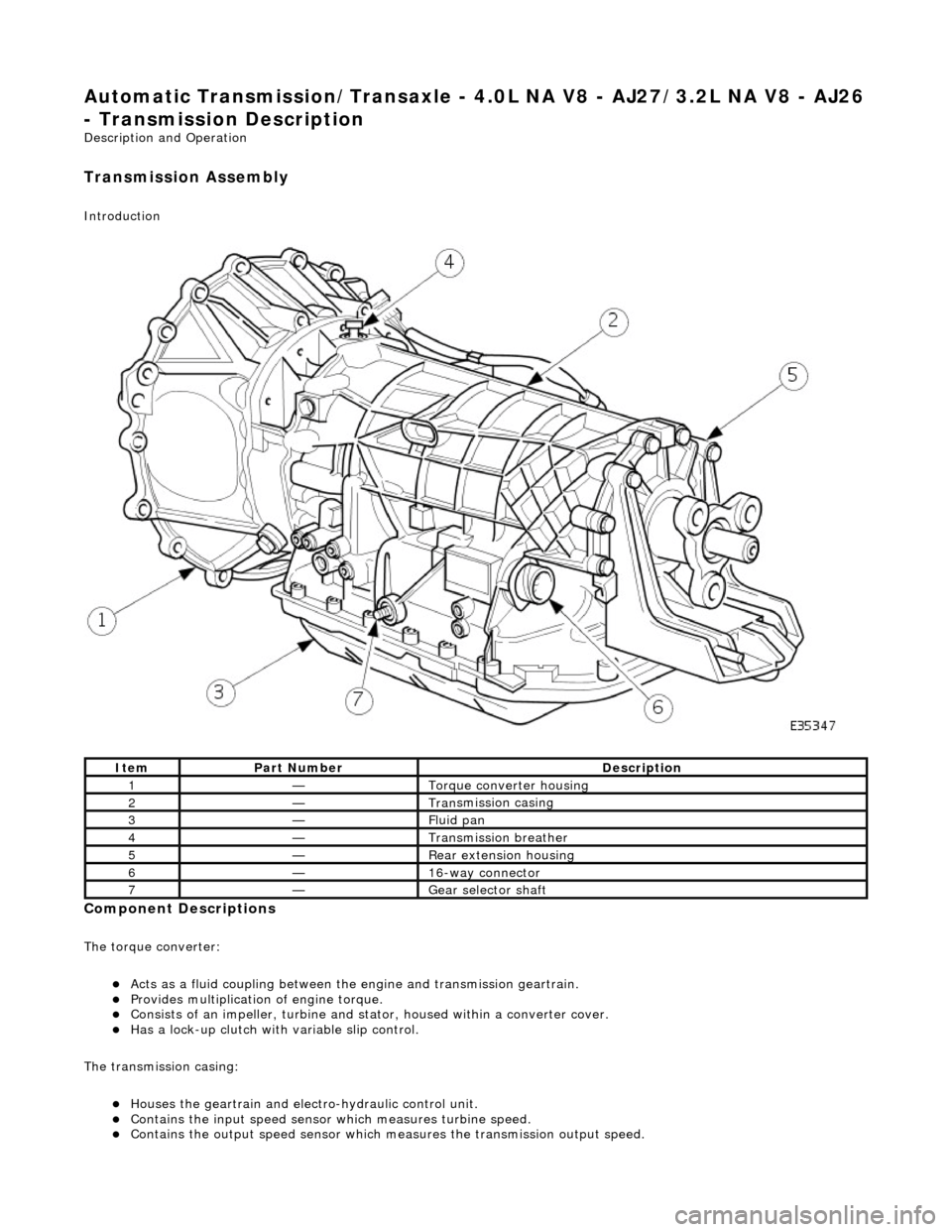
Automatic Transmission/Transaxle - 4.0L NA V8 - AJ27/3.2L NA V8 - AJ26
- Transmission Descriptio
n
Description an
d Operation
Transmission As
sembly
Int
roduction
Compon
ent Descriptions
The t
orque converter:
пЃ¬Acts as a fluid
coupling between the
engine and transmission geartrain.
пЃ¬P
rovides multiplication of engine torque.
пЃ¬Cons
ists of an impeller, turbine and stat
or, housed within a converter cover.
пЃ¬Has a l
ock-up clutch with variable slip control.
The transmission casing:
пЃ¬Houses the geartrain and elec t
ro-hydraulic control unit.
пЃ¬Contains
the input speed sensor which measures turbine speed.
пЃ¬Contai
ns the output speed sensor which measures the transmission output speed.
It
em
Par
t Number
De
scription
1—Torque c
onverter housing
2—Tran
smission casing
3—Fluid pan
4—Transmission bre
ather
5—Re
ar extension housing
6—16
-way connector
7—Gear s
elector shaft
Page 1262 of 2490
пЃ¬Contains th
e hydraulic system pump.
пЃ¬Contains
th
e fluid temperature sensor.
The epicyclic geartrain:
пЃ¬Provi des fi
ve forward gears and Reverse.
пЃ¬Has
h
ydraulically actuated, multi-disk clutches, to select the required gear ratios.
пЃ¬Feature
s clutch-to-clutch operation to permit
gear shifts for uninterrupted power flow.
The electro-hydraulic control unit:
пЃ¬Is lo c
ated in the lower part of
the unit, within the fluid pan.
пЃ¬Is controlled
by the TCM (transmissio
n control module), and the manual selector valve which is cable operated.
пЃ¬Re
gulates the flow of fluid to the ge
artrain clutches via three solenoid-operated valv es and the manual selector
valve.
пЃ¬Has fi ve pressure
regulators for controll
ing fluid pressures within the system.
пЃ¬Is con
nected to the TCM via a 16-way connector mounted on
the left-hand side of the transmission casing. Refer to
Connector Pins Identification, Section 307-01A.
The hydraulic system pump:
пЃ¬Is l o
cated at the front of the transmission casing.
пЃ¬Is dri
v
en from the impeller hub,
pressurising the fluid whenever the engine is running.
пЃ¬Supplie
s fluid under pressure to the torq
ue converter, geartrain, electro-hydr aulic control unit and the lubrication
circuit.
пЃ¬D r
aws fluid from the fluid pa
n below the transmission casing, through a filter.
The rear extension housing:
пЃ¬Is bolt
ed to the rear of the transmission casing.
пЃ¬Provides the rear engine / transmi
ssion mo
unting point; refer to section 303-01.
пЃ¬Carrie
s the transmission output shaft oil seal.
Filled-for-l
i
fe Fluid System
The
transm
ission is 'filled for life' and
does not require fluid changes, except where extreme driving conditions prevail.
Routine level checking is not required and a dipstick is not pr ovided. A level / filler plug is fitted for level checking and
replenishment, following service actions; see 303-01 General Procedures.
Transmission Torque Converter