engine oil JAGUAR X308 1998 2.G Workshop Manual
[x] Cancel search | Manufacturer: JAGUAR, Model Year: 1998, Model line: X308, Model: JAGUAR X308 1998 2.GPages: 2490, PDF Size: 69.81 MB
Page 1258 of 2490

El
ectronic Engine Controls - Variable
Camshaft Timing (VCT) Oil Control
Solenoid
Re mo
val and Installation
Remova
l
1.
Op
en the engine compartment and fit paintwork protection
sheets.
2. Disc
onnect the batt
ery ground cable.
Re
move the battery cover.
3. Disc
onnect the VVT solenoid connector.
4. Re
move the two bolts which secure the VVT solenoid to the
timing cover.
5. Pull the VVT solenoid clear and discard the O-ring.
Page 1262 of 2490
Contains th
e hydraulic system pump.
Contains
th
e fluid temperature sensor.
The epicyclic geartrain:
Provi des fi
ve forward gears and Reverse.
Has
h
ydraulically actuated, multi-disk clutches, to select the required gear ratios.
Feature
s clutch-to-clutch operation to permit
gear shifts for uninterrupted power flow.
The electro-hydraulic control unit:
Is lo c
ated in the lower part of
the unit, within the fluid pan.
Is controlled
by the TCM (transmissio
n control module), and the manual selector valve which is cable operated.
Re
gulates the flow of fluid to the ge
artrain clutches via three solenoid-operated valv es and the manual selector
valve.
Has fi ve pressure
regulators for controll
ing fluid pressures within the system.
Is con
nected to the TCM via a 16-way connector mounted on
the left-hand side of the transmission casing. Refer to
Connector Pins Identification, Section 307-01A.
The hydraulic system pump:
Is l o
cated at the front of the transmission casing.
Is dri
v
en from the impeller hub,
pressurising the fluid whenever the engine is running.
Supplie
s fluid under pressure to the torq
ue converter, geartrain, electro-hydr aulic control unit and the lubrication
circuit.
D r
aws fluid from the fluid pa
n below the transmission casing, through a filter.
The rear extension housing:
Is bolt
ed to the rear of the transmission casing.
Provides the rear engine / transmi
ssion mo
unting point; refer to section 303-01.
Carrie
s the transmission output shaft oil seal.
Filled-for-l
i
fe Fluid System
The
transm
ission is 'filled for life' and
does not require fluid changes, except where extreme driving conditions prevail.
Routine level checking is not required and a dipstick is not pr ovided. A level / filler plug is fitted for level checking and
replenishment, following service actions; see 303-01 General Procedures.
Transmission Torque Converter
Page 1269 of 2490
2.2. Check on non-volatile diagnostic memory by wr iting a test pattern and then reading it back.
3. 3. Internal 'watchdog' hardware to check whether the TCM has crashed.
Transmission Control Module Supply Voltage
The TCM monitors battery and igni tion switched supply voltages.
A permanent supply is used to maintain a battery backed 'memor y'. Should this supply be cut, due to battery disconnection
perhaps, the 'adaptive shift' valu es will be lost. This will result in a small reduction in shift quality for a period until th e
adaptions are 're-learned'
The TCM will adopt 'limp home' mode as a result of the supply voltage being >16V or <7V with an engine speed >1600
rpm.
Should the ignition supply be >7V but <9V the TCM will hold the gear that it has currently selected. If after 2.5 seconds,
with the engine speed >1600 rpm, the voltage remains at this level, 'limp home' mode will be adopted. The 2.5 second
delay is built in to prevent reaction to a momentary voltage fluctuation.
Operation
CAUTION: Disconnection of the TCM and / or the vehicle batt ery will cause system adaptions to be lost; this may be
apparent by shift quality degradation. Fo llowing reconnection, a period of 'varied' driving will reinstate adaptions and thus
normal operation. Please ensure that the customer is made aware that the adaption period is variable and may occur after
handover, as the transmission re-learns the prevailing driving style.
• NOTE: Should the TCM fail, please ensure that the control housing cooling fan is operating correctly. Failure of the cooling
fan MUST be rectified before renewing the TCM and details of a fan fa ilure should accompany the returned TCM.
The TCM processes information received in both analogue and digital form, such as:
Transmission input speed Transmission output speed Throttle position Pedal demand Gear selector position Engine torque Engine speed Transmission oil temperature Mode switch
This information is then used by the TC M to control shift energy management and decide which shift program to implement
and which gear to select.
The TCM uses the various sensors and inpu ts to monitor the correct operation of the system an d is programmed to take
default action and inform the operator when a fault occurs.
Safety Functions
The safety functions are designed to safeguard against inappr opriate actions by the operator as well as against system
malfunctions. The system prevents reve rse gear from being engaged at high forward speeds and prevents manual
downshifting at excessive engine speeds; these functions are not operational in mechanical limp-home mode.
The TCM constantly monitors the transmissi on for faults. In the event of a problem the TCM will adopt a 'limp home' mode
in which only P R N D - (selector in D but only fourth gear is enabled) are available. The operator will be made aware of
certain faults by an in strument panel warning.
The electrical and diagnostic system has been designed such that system integrity is protected at all times, the safety
concept being based on th e following three points:
Page 1270 of 2490
1.1. The hydraulic system has 'fail-safe' characteristics regardin g its electrical operation, such that should the power
supply be lost to the electro-hydraulic actuators the transmission will initiate a limp-home mode.
2. 2. Recognition of critical shift operation by monitoring the last element in the signal path, ie the solenoid valve, and
checking by means of redundant me asured variables, ie engine speed, input speed and output speed.
3. 3. Each time the vehicle is started there is a check on the entire safety hardware and the associated program parts
and signal paths. A malfunction in this part of the system, or triggering of the safety circuit, is communicated to
the operator through the illumination of the transmission warning lamp.
TCM Inputs
Input Speed Sensor (Torque Converter Turbine)
The input speed sensor provides the TCM with transmission inpu t shaft speed information. This signal is produced from an
inductive pick-up, generating 30 pulses per revolution.
Transmission Output Speed Sensor
The output speed sensor provides the TCM with transmission ou tput shaft speed information. This signal is produced from
an inductive pick-up, generati ng 36 pulses per revolution.
Transmission Oil Temperature Sensor
A thermistor which provides an electrical indication of the oi l temperature to the TCM. The signal is measured as a voltage
with reference to analog ue ground in the TCM.
Kickdown Switch (where fitted)
Kickdown is intended to provide maximum vehicle acceleration , via the appropriate downshift(s), when the operator uses
full throttle. A kickdown switch provides an electrical signal to the TCM wh en the accelerator pedal is fully pressed. The
switch is normally open, connected to vehicle ground. Should the switch fail the TCM will detect kickdown using the
accelerator pedal position.
Throttle Pedal Stop (where fitted)
This component, used where the kickdown switch is not fitted, limits throttle pedal travel .in the same way. The kickdown
feature is retained, but is controlled by throttle position only. The pedal stop must be set, using the PDU, in the same way
as the kickdown switch to optimize performance.
Mode Selection Switch
The mode selection switch is a two position switch indicati ng to the TCM the current performance mode selected by the
driver. The switch generates a tw o-bit digital input to the TCM.
Rotary Position Switch
The rotary position switch detects the position of the transmis sion selector shaft. The switch is supplied as part of a new
transmission assembly, mounted on the transmission body. The swit ch is used to indicate to the TCM the six positions of the shaft: Park, Reverse, Neutral, Drive, Third and Second. The switch provides a four-bit input to the TCM.
Drive to Fourth Switch
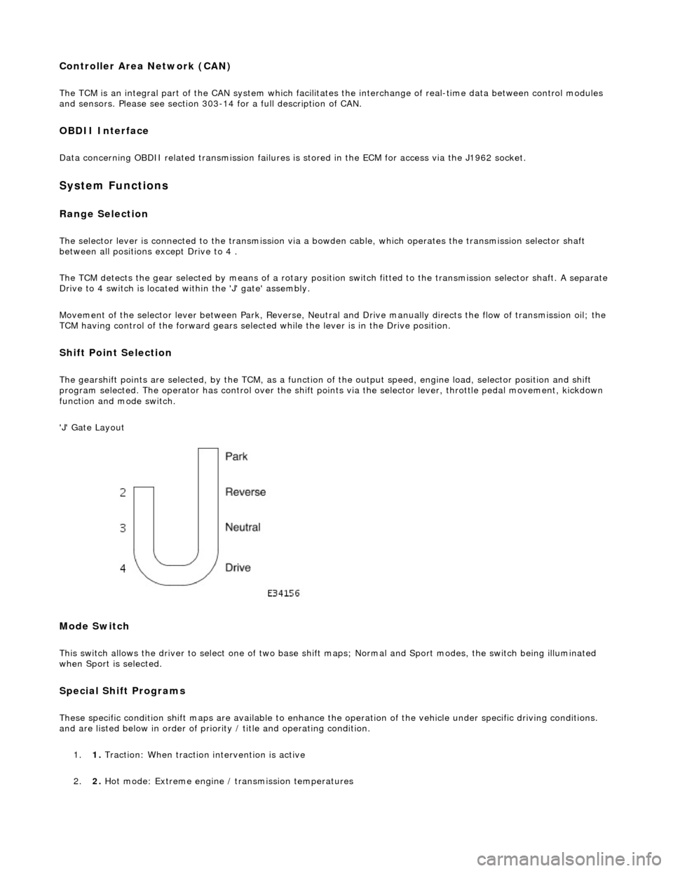
Detects the movement of the selector lever from Drive to Fourth position. The selector cable, and therefore the transmission selector shaft, does not move as the lever is operated between these two positions. The switch is located within the 'J-gate'
assembly, producing a digital output to indicate to the TCM that the lever has moved from D to 4 .
Serial Communications Interfaces
Page 1271 of 2490
Controller Area Network (CAN)
The TCM is an integral part of the CAN system which facilitates the interchange of real-time data between control modules
and sensors. Please see section 303- 14 for a full description of CAN.
OBDII Interface
Data concerning OBDII related transmission failures is stored in the ECM for access via the J1962 socket.
System Functions
Range Selection
The selector lever is connected to the transmission via a bowden cable, which operates the transmission selector shaft
between all positions except Drive to 4 .
The TCM detects the gear selected by means of a rotary position switch fitted to the transmission selector shaft. A separate
Drive to 4 switch is located within the 'J' gate' assembly.
Movement of the selector lever between Park, Reverse, Neutral and Drive manually directs th e flow of transmission oil; the
TCM having control of the forward gears selected while the lever is in the Drive position.
Shift Point Selection
The gearshift points are selected, by the TCM, as a function of the output speed, engine load, selector position and shift
program selected. The operator has control over the shift points via the selector lever, throttle pedal movement, kickdown
function and mode switch.
'J' Gate Layout
Mode Switch
This switch allows the driver to select one of two base shift maps; Normal and Sport modes, the switch being illuminated
when Sport is selected.
Special Shift Programs
These specific condition shift maps are available to enhance the operation of the vehicle under specific driving conditions.
and are listed below in order of priority / title and operating condition.
1. 1. Traction: When traction intervention is active
2. 2. Hot mode: Extreme engine / transmission temperatures
Page 1336 of 2490
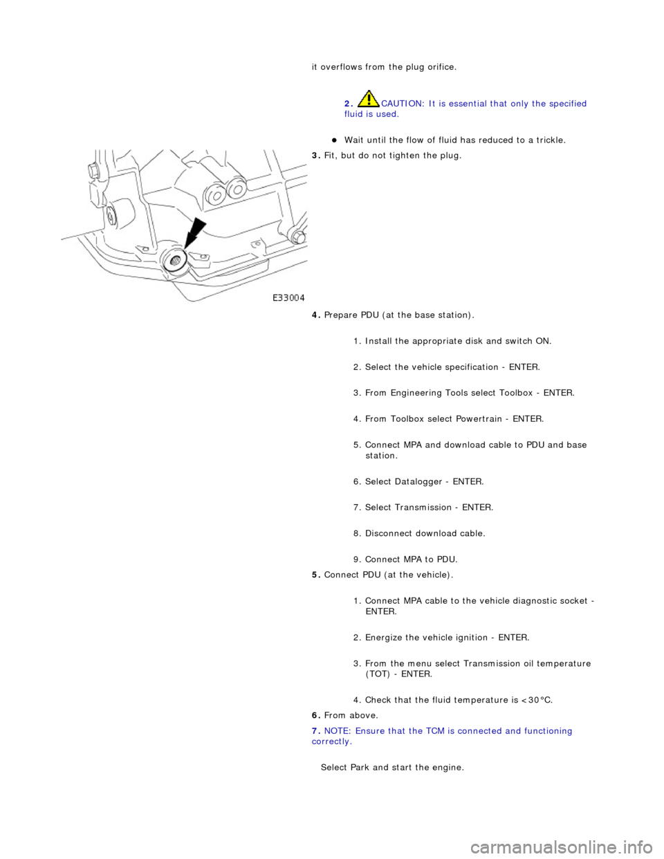
it overflows from the plug orifice. 2. CAUTION: It is essential that only the specified
fluid is used.
Wait until the flow of fluid has reduced to a trickle.
3. Fit, but do not tighten the plug.
4. Prepare PDU (at the base station).
1. Install the appropriat e disk and switch ON.
2. Select the vehicle specification - ENTER.
3. From Engineering Tools select Toolbox - ENTER.
4. From Toolbox select Powertrain - ENTER.
5. Connect MPA and download cable to PDU and base station.
6. Select Datalogger - ENTER.
7. Select Transmission - ENTER.
8. Disconnect download cable.
9. Connect MPA to PDU.
5. Connect PDU (at the vehicle).
1. Connect MPA cable to the vehicle diagnostic socket -
ENTER.
2. Energize the vehicle ignition - ENTER.
3. From the menu select Transmission oil temperature (TOT) - ENTER.
4. Check that the fluid temperature is <30°C.
6. From above.
7. NOTE: Ensure that the TCM is connected and functioning
correctly.
Select Park and start the engine.
Page 1391 of 2490
In the event of a system fault, the TCM will adopt 'limp home' mode.
Electrical control
Refer to Section 307-01B.
Transmission Control Components
Transmission Control Module (TCM)
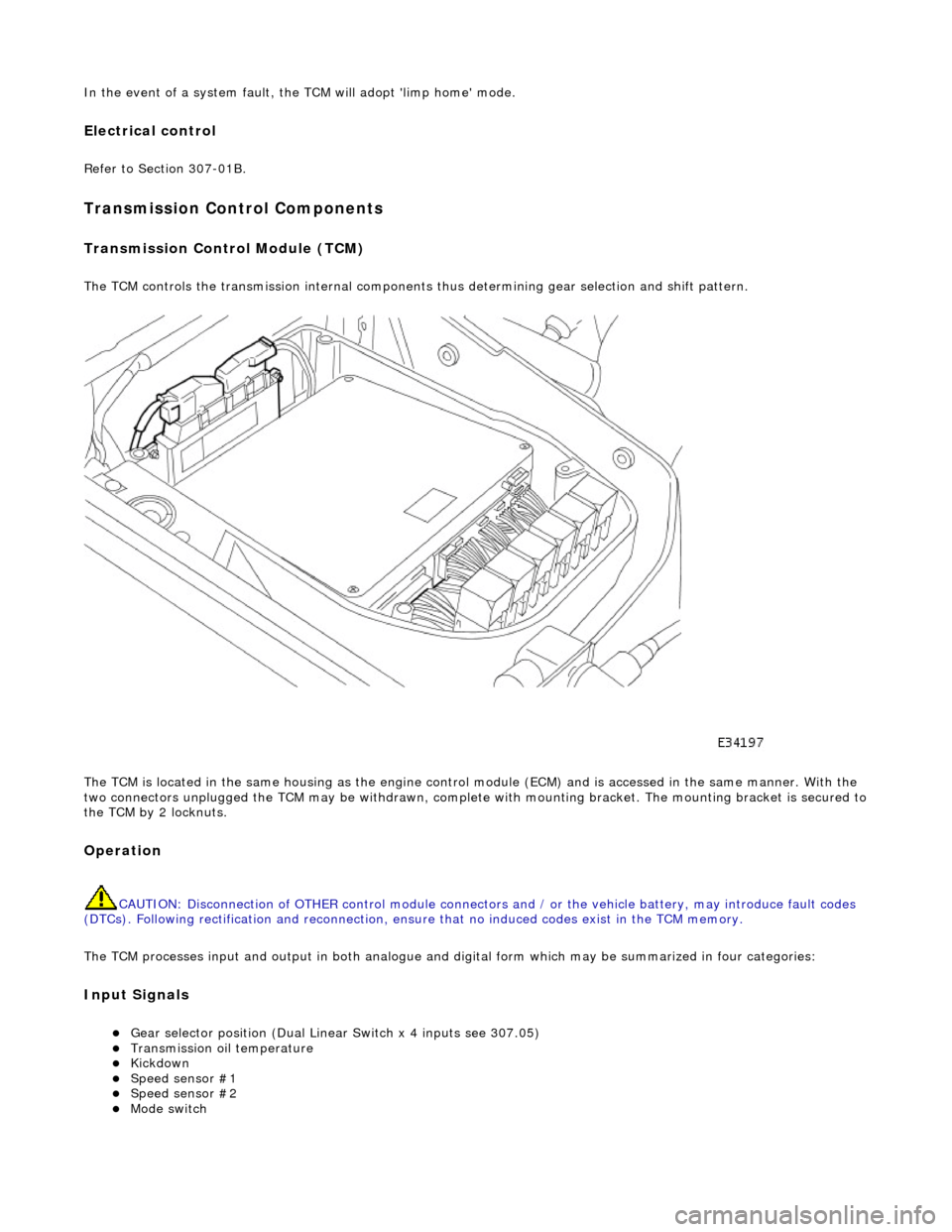
The TCM controls the transmission internal components thus determining gear selection and shift pattern.
The TCM is located in the same housing as the engine control module (ECM) and is accessed in the same manner. With the
two connectors unplugged the TCM may be withdrawn, complete with mounting bracket. The mounting bracket is secured to
the TCM by 2 locknuts.
Operation
CAUTION: Disconnection of OTHER contro l module connectors and / or the vehicle battery, may introduce fault codes
(DTCs). Following rectification and reconnection, ensu re that no induced codes exist in the TCM memory.
The TCM processes input and output in both analogue and di gital form which may be summarized in four categories:
Input Signals
Gear selector position (Dual Linear Switch x 4 inputs see 307.05) Transmission oil temperature Kickdown Speed sensor #1 Speed sensor #2 Mode switch
Page 1392 of 2490
CAN Input Signals
Traction status ABS malfunction ABS status Engine torque status Throttle position Accelerator pedal position Engine torque reduction confirmation Engine speed Engine coolant temperature Cruise status OBDII fault code clear request Throttle malfunction warning RED or AMBER All road wheel speeds Token for network status ECM Token for network status INST Token for network status ABS Diagnostic data in from external device (PDU)
Output Signals
Solenoid valve 1 <-> 2 and 4 <-> 5 shift Solenoid valve 2 <-> 3 shift Solenoid valve 3 <-> 4 shift Solenoid valve converter lock-up clutch Control valve - modulating pressure Control valve - shift pressure
CAN Output Signals
Engine torque reduction request MIL status (whether present DTC should operate MIL) Transmission input speed Transmission output speed Converter slip Kickdown status Gear position (actual) Gear position (selected) Gear selection fault Converter lock-up status Current selected shift map Transmission oil temperature Transmission malfunction Pecus flag (state of current TCM program) Target for next gear position Gear shift torque transfer progress at shift MIL status (response to activate the MIL relevant to a DTC) OBDII fault code clear acknowledgement Transmission DTCs (P codes) Token for network status TCM Diagnostic data out to external device (PDU)
Emergency Running (elect ronic limp-home mode)
The TCM constantly monitors the transmissi on for faults. In the event of a problem the TCM will adopt the limp-home mode, in which the gear currently held remains engaged, until P is selected. The modulati ng and shift pressures will increase to
maximum and converter lock-up will be inhibited.
Following the selection of P , the only ratios available will be 2 (irrespective of forward ratio manual selection) and R .
With the vehicle at rest, the procedure to manually select is as follows:
1. 1. Select P .
Page 1433 of 2490

Automatic Transmission/Transaxle - 4.0L SC V8 - AJ26 - Extension
Housing Seal
In-vehicle Repair
Removal
Special Tool(s)
Oil seal replacer
307-378
Driveshaft wrench
205-053
1. Disconnect the battery ground lead.
2. Select N and choc the road wheels.
3. Remove the front muffler, re fer to Operation 30.10.18.
4. Remove the engine rear mounting bracket.
1. Support the transmission.
2. Remove the bolt, engine rear mounting to transmission.
3. Remove the four bolts which secure the mounting
cross member to the body.
5. Detach the driveshaft from th e transmission drive flange.
1. If the transmission is to be refitted, mark the position of the coupling relative to the drive flange.
5. CAUTION: Under no circ umstances remove the
driveshaft to flexible coupling fixings.
2. Remove the three bolts, tr ansmission drive flange to
flexible coupling.
6. Secure the driveshaft wrench 205 - 053 to the output shaft
flange.
Page 1459 of 2490

6. Fit the mounting bracket for th e front muffler. Tighten the two
bolts to the specified torque figure.
7. Secure the transmission to the engine.
Loosely assemble - Cooler pipe clip bolt.
Loosely assemble - Ground lead bolt.
Loosely assemble - Starter cable clips, two bolts.
Loosely assemble - Catalyst bracket bolts, two each side.
Loosely assemble - Rema ining eight bolts.
Refer to the illustration - tighten in sequence 1,2,3,4 then
in any order.
8. Secure the torque converter to the engine.
1. Fit, but do not tighten, the three bolts which secure the torque converter to the drive plate.
Prevent crankshaft rotation and tighten ALL converter
bolts to the specified torque figure.
2. Fit the blanking plug to the cylinder block access aperture.
9. Secure the oil cooler pipes.
Fit new Dowty washers to each union. Connect the upper
and lower cooler pipes.
Tighten to the specified torque figure.