air control JAGUAR X308 1998 2.G Workshop Manual
[x] Cancel search | Manufacturer: JAGUAR, Model Year: 1998, Model line: X308, Model: JAGUAR X308 1998 2.GPages: 2490, PDF Size: 69.81 MB
Page 1848 of 2490
Control Components - Remote Climate Control ModuleRHD RWD
Removal and Installation
Removal
1. Position the driver's seat fully rearward
2. Position the steering column DOWN and fully EXTENDED
3. Disconnect the battery ground lead
4. Lower steering column cowl 76.46.03
5. Upper steering column cowl 76.46.02
6. Knee bolster, driver's side 76.46.11
7. Position the steering in the 'straight ahead'
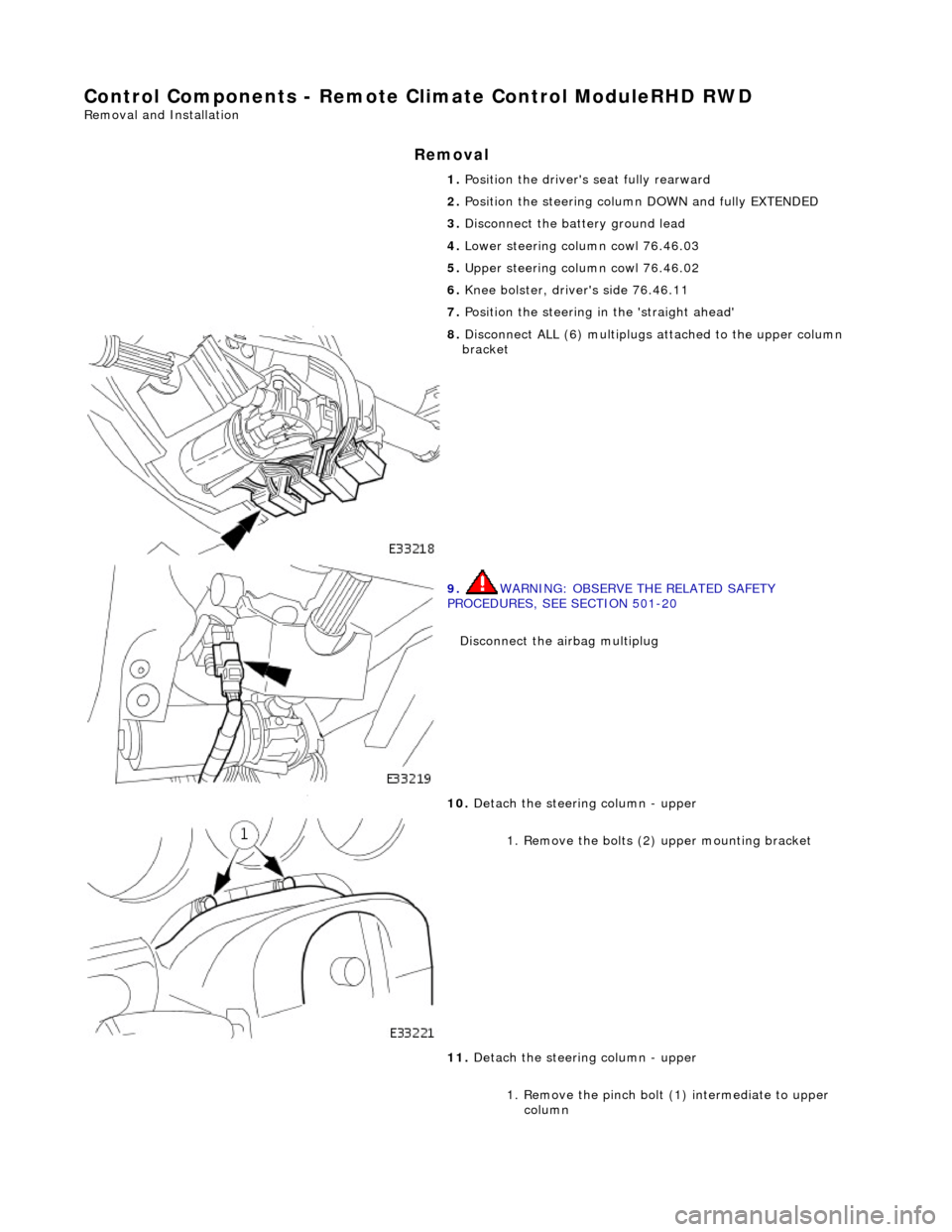
8. Disconnect ALL (6) multiplugs attached to the upper column
bracket
9. WARNING: OBSERVE THE RELATED SAFETY
PROCEDURES, SEE SECTION 501-20
Disconnect the airbag multiplug
10. Detach the steering column - upper
1. Remove the bolts (2 ) upper mounting bracket
11. Detach the steering column - upper
1. Remove the pinch bolt (1) intermediate to upper column
Page 1855 of 2490
The In
strument Cluster is the primary electronic control module for the speedomete
r, tachometer, coolant temperature, fuel
level, driver information (Message Centre) and warning lamps.
The Instrument Cluster also:
- provides input / output informatio n signals for use by other modules.
- acts as a protocol converter (software language translator - the languages used on each network are very similar, but
neither can be directly interp reted by the opposite system) for communication between all modules on both the CAN and
SCP multiplexed networks. The Instrument Cluster is the only module on the vehicle which communicates between the two
networks.
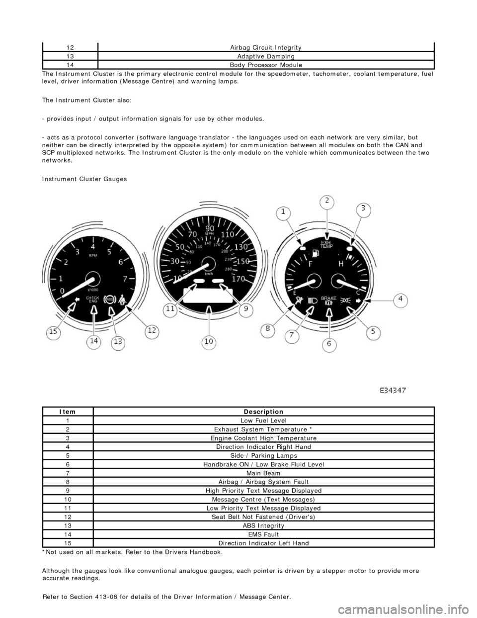
Instrument Cluster Gauges
*Not used on all markets. Refer to the Drivers Handbook.
Although the gauges look like conventional analogue gauges, each pointer is driven by a stepper motor to provide more
12Ai
rbag Circuit Integrity
13Adaptive Damping
14Body Processor
Module
It
em
De
scription
1Low Fu
el Level
2Exhaus
t System Temperature *
3E
ngine Coolant High Temperature
4Di
rection Indicator Right Hand
5Side
/ Parking Lamps
6Handbrake ON / Low
Bra
ke Fluid Level
7Main
Beam
8Ai
rbag / Airbag System Fault
9Hi
gh Priority Text
Message Displayed
10M
essage Centre (Text Messages)
11Low Pri
ority Text Message Displayed
12Se
at Belt Not Fa
stened (Driver's)
13ABS Integrity
14EMS Fault
15D
irection Indicator Left Hand
accu
rate readings.
Refer to Section 413-08 for details of the Driver Information / Message Center.
Page 1889 of 2490
CAUTION: The engine must not be running when multiplugs are connected or disconnected.
Check that the main B+ terminal is clean and tight.
Check that the IG terminal is clean and ma king good contact; if this connection is faulty, the generator will never function
correctly.
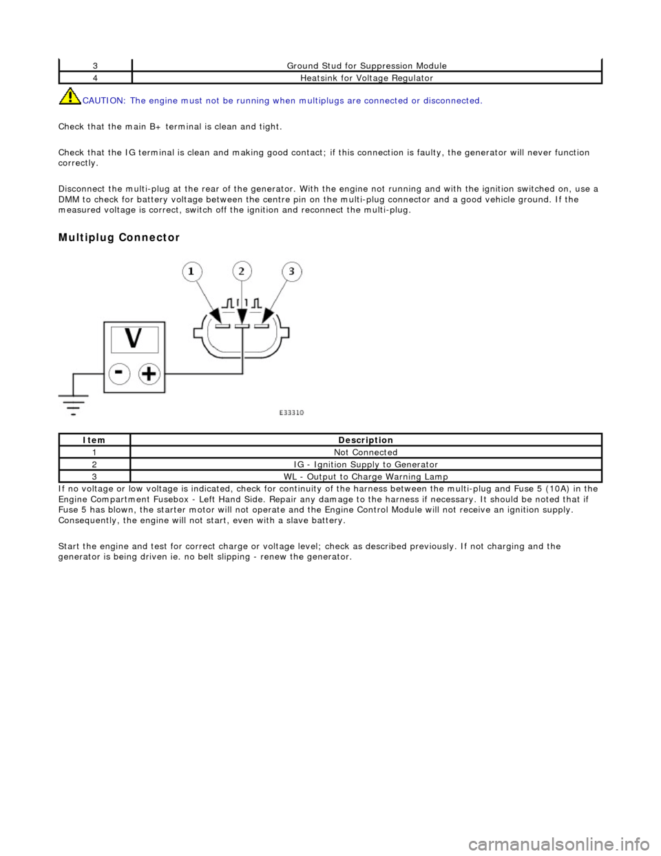
Disconnect the multi-plug at th e rear of the generator. With the engine not running and with the ignition switched on, use a
DMM to check for battery voltage between the centre pin on the multi-plug connector and a good vehicle ground. If the
measured voltage is correct, switch off the ignition and reconnect the multi-plug.
Multiplug Connector
If no voltage or low voltage is indicated, check for continuity of the harness between the multi-plug and Fuse 5 (10A) in the
Engine Compartment Fusebox - Left Hand Si de. Repair any damage to the harness if necessary. It should be noted that if
Fuse 5 has blown, the starter motor will not operate and the Engine Control Module will not receive an ignition supply.
Consequently, the engine will not st art, even with a slave battery.
Start the engine and test for correct ch arge or voltage level; check as described previously. If not charging and the
generator is being driven ie. no be lt slipping - renew the generator.
3Ground Stud for Suppression Module
4Heatsink for Voltage Regulator
ItemDescription
1Not Connected
2IG - Ignition Supply to Generator
3WL - Output to Charge Warning Lamp
Page 1904 of 2490
Audio Unit - Audio System
Description and Operation
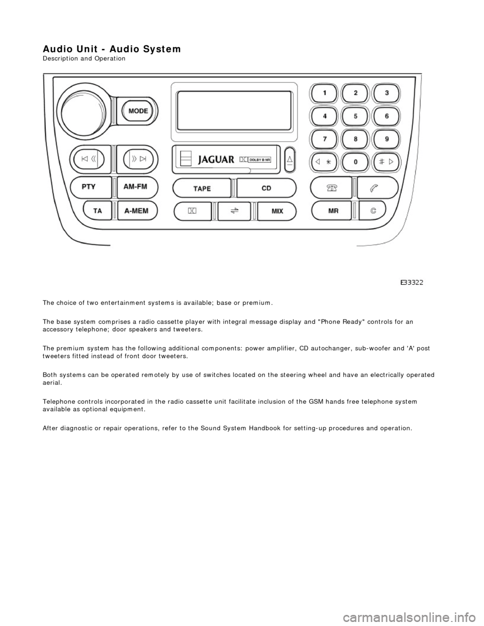
The choice of two entertainment system s is available; base or premium.
The base system comprises a radio cassette player with in tegral message display and "Phone Ready" controls for an
accessory telephone; door speakers and tweeters.
The premium system has the following additional components: power amplifier, CD autochanger, sub-woofer and 'A' post
tweeters fitted instead of front door tweeters.
Both systems can be operated remotely by use of switches loca ted on the steering wheel and have an electrically operated
aerial.
Telephone controls incorporated in the ra dio cassette unit facilitate inclusion of the GSM hands free telephone system
available as optional equipment.
After diagnostic or repair operations, refer to the Sound System Handbook for setting-up procedures and operation.
Page 1975 of 2490
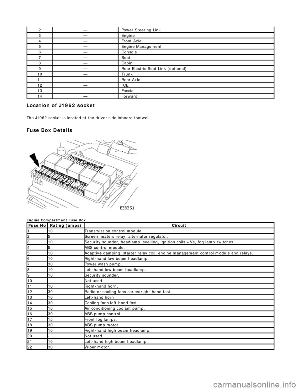
Location of J1962 socket
The J1962 socket is located at the driver side inboard footwell.
Fuse Box Details
Engine Compartment Fuse Box
2—Power Steering Link
3—Engine
4—Front Axle
5—Engine Management
6—Console
7—Seat
8—Cabin
9—Rear Electric Seat Link (optional)
10—Trunk
11—Rear Axle
12—ICE
13—Fascia
14—Forward
Fuse NoRating (amps)Circuit
110Transmission control module.
25Screen heaters relay, alternator regulator.
310Security sounder, headlamp levelling, ignition coils +Ve, fog lamp switches.
45ABS control module.
510Adaptive damping, starter relay coil, engine management control module and relays.
610Right-hand low beam headlamp.
730Power wash pump.
810Left-hand low beam headlamp.
910Security sounder.
10-Not used.
1110Right-hand horn.
1230Radiator cooling fans series/right-hand fast.
1310Left-hand horn
1430Cooling fans left-hand fast.
1510Air conditioning coolant pump.
1630ABS pump control.
1715Front fog lamps.
1830ABS pump motor.
1910Right-hand high beam headlamp.
20-Not used.
2110Left-hand high beam headlamp.
2230Wiper motor.
Page 1976 of 2490
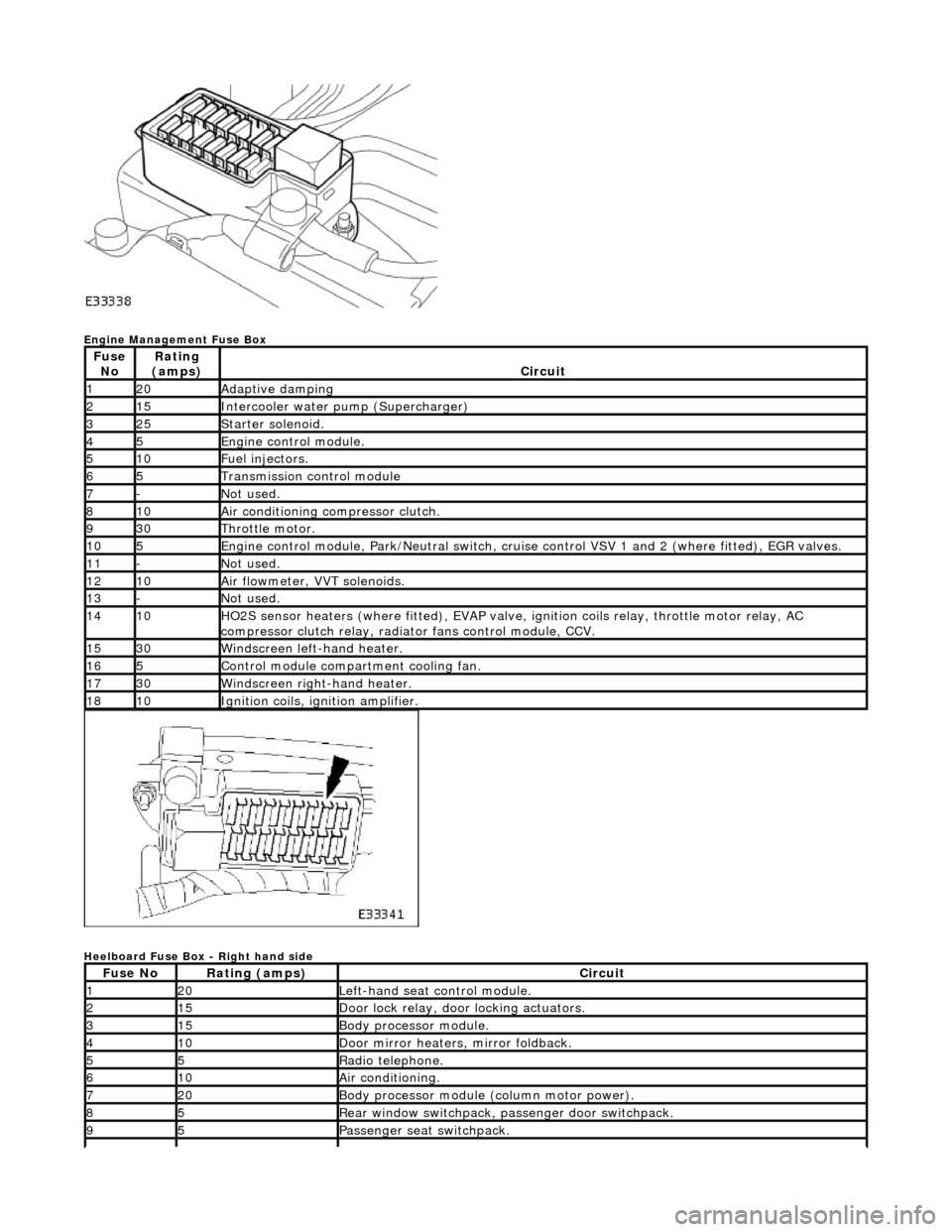
Engine Management Fuse Box
Heelboard Fuse Box - Right hand side
Fuse NoRating
(amps)Circuit
120Adaptive damping
215Intercooler water pump (Supercharger)
325Starter solenoid.
45Engine control module.
510Fuel injectors.
65Transmission control module
7-Not used.
810Air conditioning compressor clutch.
930Throttle motor.
105Engine control module, Park/Neutr al switch, cruise control VSV 1 and 2 (where fitted), EGR valves.
11-Not used.
1210Air flowmeter, VVT solenoids.
13-Not used.
1410HO2S sensor heaters (where fitted ), EVAP valve, ignition coils relay, throttle motor relay, AC
compressor clutch relay, radi ator fans control module, CCV.
1530Windscreen left-hand heater.
165Control module compartment cooling fan.
1730Windscreen right-hand heater.
1810Ignition coils, ignition amplifier.
Fuse NoRating (amps)Circuit
120Left-hand seat control module.
215Door lock relay, door locking actuators.
315Body processor module.
410Door mirror heaters, mirror foldback.
55Radio telephone.
610Air conditioning.
720Body processor module (column motor power).
85Rear window switchpack, passenger door switchpack.
95Passenger seat switchpack.
Page 1977 of 2490
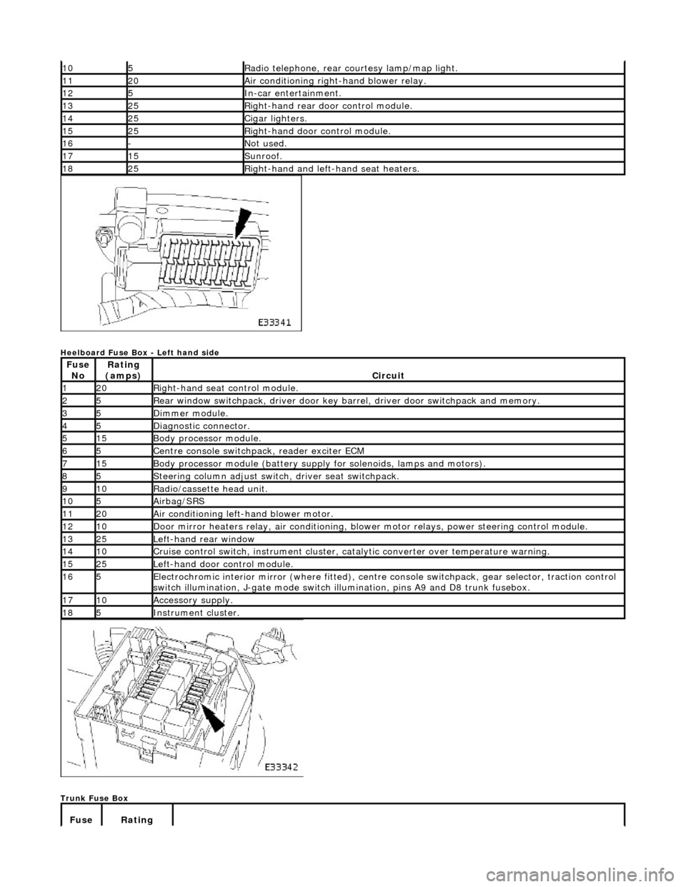
Heelboard Fuse Box - Left hand side
Trunk Fuse Box
105Radio telephone, rear courtesy lamp/map light.
1120Air conditioning right-hand blower relay.
125In-car entertainment.
1325Right-hand rear door control module.
1425Cigar lighters.
1525Right-hand door control module.
16-Not used.
1715Sunroof.
1825Right-hand and left-hand seat heaters.
Fuse NoRating
(amps)Circuit
120Right-hand seat control module.
25Rear window switchpack, driver door key ba rrel, driver door switchpack and memory.
35Dimmer module.
45Diagnostic connector.
515Body processor module.
65Centre console switchpack, reader exciter ECM
715Body processor module (battery supply for solenoids, lamps and motors).
85Steering column adjust switch, driver seat switchpack.
910Radio/cassette head unit.
105Airbag/SRS
1120Air conditioning left-hand blower motor.
1210Door mirror heaters relay, air conditioning, blow er motor relays, power steering control module.
1325Left-hand rear window
1410Cruise control switch, instrument cluster, catalytic converter over temperature warning.
1525Left-hand door control module.
165Electrochromic interior mirror (where fitted), centre console switchpack, gear selector, traction control
switch illumination, J-gate mode switch illumination, pins A9 and D8 trunk fusebox.
1710Accessory supply.
185Instrument cluster.
Fuse Rating
Page 1978 of 2490
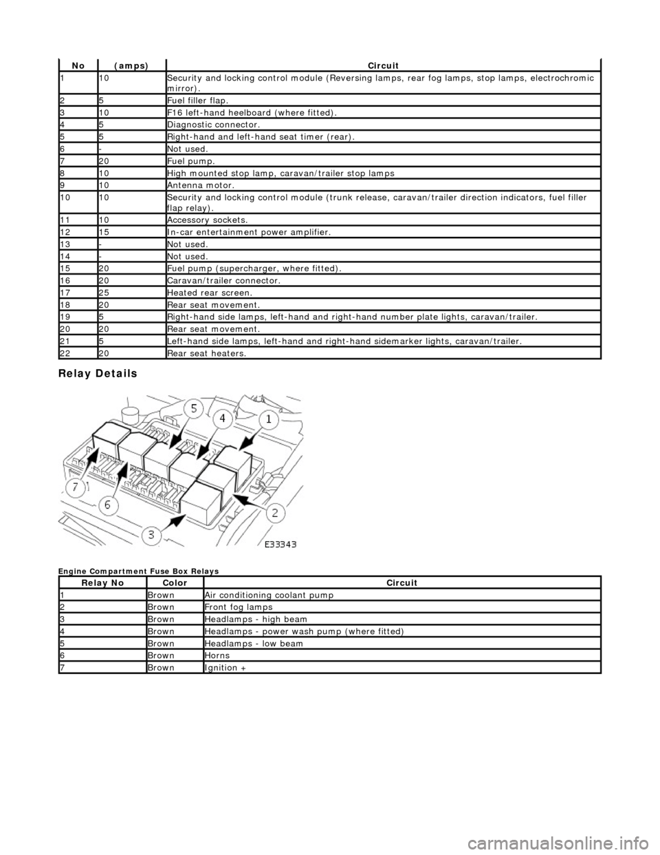
Relay Details
Engine Compartment Fuse Box Relays
No(amps)Circuit
110Security and locking control module (Reversing lamps, rear fog lamps, stop lamps, electrochromic
mirror).
25Fuel filler flap.
310F16 left-hand heelboard (where fitted).
45Diagnostic connector.
55Right-hand and left-han d seat timer (rear).
6-Not used.
720Fuel pump.
810High mounted stop lamp, caravan/trailer stop lamps
910Antenna motor.
1010Security and locking control module (trunk release, caravan/trailer direction indicators, fuel filler
flap relay).
1110Accessory sockets.
1215In-car entertainment power amplifier.
13-Not used.
14-Not used.
1520Fuel pump (supercharger, where fitted).
1620Caravan/trailer connector.
1725Heated rear screen.
1820Rear seat movement.
195Right-hand side lamps, left-h and and right-hand number pl ate lights, caravan/trailer.
2020Rear seat movement.
215Left-hand side lamps, left-hand and right-hand sidemarker lights, caravan/trailer.
2220Rear seat heaters.
Relay NoColorCircuit
1BrownAir conditioning coolant pump
2BrownFront fog lamps
3BrownHeadlamps - high beam
4BrownHeadlamps - power wash pump (where fitted)
5BrownHeadlamps - low beam
6BrownHorns
7BrownIgnition +
Page 1979 of 2490
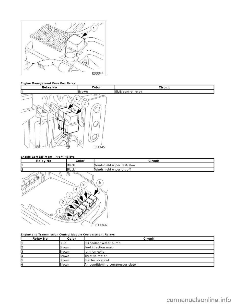
Engine Management Fuse Box Relay
Engine Compartment - Front Relays
Engine and Transmission Control Module Compartment Relays
Relay NoColorCircuit
1BrownEMS control relay
Relay NoColorCircuit
1BlackWindshield wiper fast/slow
2BlackWindshield wiper on/off
Relay NoColorCircuit
1BlueSC coolant water pump
2BrownFuel injection main
3BrownIgnition coils
4BrownThrottle motor
5BrownStarter solenoid
6BrownAir conditioning compressor clutch
Page 2022 of 2490
Body closures
Each front and rear door consists of a welded, mild steel inner frame and an outer panel. The outer panel is welded to the
waist rail and cheater of the inner frame, then bonded and clinched to fo rm the door assembly. Cosmetic PVC bead is
applied to all clinch joints. Sp onge rubber seals are mounted on the doors. Inte rnal insulation is provided by a foam water
shedder attached to the door by double-sided adhesive tape.
The door aperture B/C posts are reinforced over their full height to fully satisfy all forthcoming European and Federal side
impact legislation. The hood consists of one piece inner and outer panels clinched and bonded together, with cosmetic bead
PVC sealant applied to all clinch joints. Th e hood pivots at the front on two hinges each secured by bolts to the hood front
underside and the BIW front upper crossmem ber. Two gas struts secured to the hood by pivot pins and snap-on couplings,
support the hood in the open position. A full width insulating pad is secured by screws to the underside of the hood. A
sponge rubber tubular seal is mounted tran sversely towards the front of the hood underside. The trunk lid is of similar
construction to the hood, consisting of inner and outer pa nels clinched and bonded together and PVC bead sealed.
Incorporating a removable moulded liner and two trunk illuminati on lights, the trunk lid is supported when open, by two gas
struts, each secured to the inner wheel arch and trunk hinge by snap fittin gs. For some markets, a warning triangle is
attached to a bracket on the trunk lid underside and is retained in the open position by a rubber block.
Fascia
One-piece slush-moulded fascia on inject ion moulded armature and steel cross-rail reinforcement. Fascia support brackets
set with BIW to achieve close tolerance fit of fascia to bo dy eliminate necessity for adjustment following removal and
installation..
Fuel Filler Flap
The fuel filler comprising a hinged flap attached to the body decking panel by tw o nuts, incorporates a rubber buffer, snap-
in striker, hinge spring and fuel cap stowage magnet. The rubber fuel bowl moulding is attached via a steel armature to the
body reinforcement panel by five M5 nuts and is retained at the filler neck by a clip. The mating drain tube is fitted with an
internal filter. The fuel filler flap latch mechanism attached to the fuel bowl armatu re by two M5 nuts, includes a locking pin
and actuator which are both se rviceable items. The latch actuator operates independently from the central locking system;
it is driven directly by the se curity and locking control module. Locking of the fuel filler flap is achi eved only by operation of
the key or by the remote rf transmitter.
Seating
All front seats are equipped with electric height adjustment. In addition, both seats are available with manual or power
forward and rearward adjustment, manual or power operated headrest adjustment, 12 way electric adjustment, memory
controlled 12 way seat adjustment and integral seat heating. A side air bag module is installe d in the outboard squab wing
of each front seat. Each front seat has a non-handed, one-piece frame incorporatin g cushion and squab frames, side air bag
support bracket and seat adjuster mechanis ms. Seat switchpacks are installed on the outboard side of driver and passenger
seats and control modules are installed in the base of each seat . The standard rear seat is of fixed, bench type with full
width removable cushion. For certain mark ets, two individual rear seats are available as an option on long wheelbase
models. Both type s of rear seat are available with th ermostatically controlled heating of the cushion and sq uab. Individual
rear seats are electrically adjustable fo r squab re cline (via cushion fore and af t movement), head restraint height and
lumbar support. Separate motors provide ad justment of each seat cushion and head restraint and an electrically driven air
compressor provides variation of lumbar support. Seat adjustment is controlled via switches installed on a panel in an
extension to the centre console.Both the driver and front pass enger seat are secured to the vehicle floor at four points.
Interior Trim
The one-piece door casings are trimmed in UEV to match the seating, with wood veneer at the waistline and a carpet insert
at the front lower corner. Each casing is secured to the door inner panel by fir tree fastener s along the lower section, two
armrest fixings at the centre and veneer panel dowels and fixings at the top. The armrests which are common to front and
rear doors, are trimmed in matc hing leather or UEV according to specification. Switchpacks dedicated to driver and front or
rear passenger, are incorporated in the ar mrests. A speaker is installed in the lower section of each door and a tweeter is
incorporated behind each interior door handle escutcheon. where premium ICE is fitted, the front tweeters are installed in
the upper A posts. On each side, a graine d UEV finisher trimmed to match the head lining is secured to the 'A' post and
cantrail by fir tree fasteners locating in BIW apertures. Th e upper 'D' post finisher is trimmed and secured in the same
manner. The single piece'B' post finishers, also finished in grained matching UEV, each have a front seat belt exit aperture
and are secured to the BIW by four spring clips and two fir tree fasteners. The one-piece headlining consists of a 6mm thick
polyurethane foam membrane covered with suede effect knitted polyester. The headlining is secured to the BIW roof by
body tangs, the roof console, sun visors, combined grab handles and coat hooks, th e cantrail finishers and where fitted, the