lower JAGUAR X308 1998 2.G Workshop Manual
[x] Cancel search | Manufacturer: JAGUAR, Model Year: 1998, Model line: X308, Model: JAGUAR X308 1998 2.GPages: 2490, PDF Size: 69.81 MB
Page 678 of 2490

6. Rotate the crankshaft until the triangular arrow indent on
the drive plate is visible thro ugh the access hole; confirm
that the timing flat on ea ch camshaft is uppermost.
7. Install the crankshaft setting peg 303-531 to the crankshaft
position sensor location.
1. Install the crankshaft setting peg 303-531.
Position the crankshaft so that the setting peg engages
fully into the timing slot.
2. Install and tighten the bolt to secure the setting peg.
8. Lower the vehicle on the ramp.
9. Install the camshaft locking tool 303-530 to Bank 1 camshafts,
aligning the shafts sl ightly as necessary.
10. CAUTION: Use a length of steel strip that will not fall
into the timing cover.
Protect the upper face of the ti ming cover from scratches, when
Page 681 of 2490

Whilst applying the opposing force to the sprocket and
chain, tighten the sprocket securing bolt to 115-125 Nm.
Remove the chain tensioning tool.
6. Remove the tape and steel stri p from the timing cover upper
face. Wipe any residue of tape from the joint face.
7. Remove the camshaft locking tool.
8. Install the Cam Cover to Bank 1. Refer to Operation 12.29.44.
9. Raise the vehicle on the ramp.
10. Remove the crankshaft setting tool 303-531.
11. Install the crankshaft position sensor.
1. Install the sensor to the flywheel housing and fit the
securing bolt. Tighten to 8-12 Nm.
2. Install the access grommet to the housing.
12. Lower the ramp.
13. Remove the paint protection sheets and close the engine
compartment cover.
14. Connect the battery and in stall the battery cover.
Refer to the Battery Reconnection Procedure 86.15.15.
Page 708 of 2490
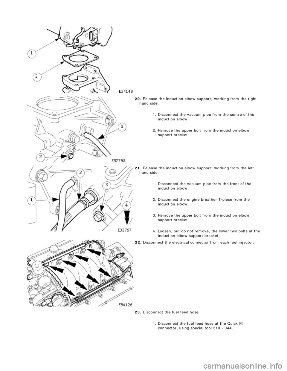
20. Release the induction elbow su pport; working from the right
hand side.
1. Disconnect the vacuum pi pe from the centre of the
induction elbow.
2. Remove the upper bolt from the induction elbow support bracket.
21. Release the induction elbow su pport; working from the left
hand side.
1. Disconnect the vacuum pipe from the front of the
induction elbow.
2. Disconnect the engine breather T-piece from the induction elbow.
3. Remove the upper bolt from the induction elbow support bracket.
4. Loosen, but do not remove , the lower two bolts at the
induction elbow support bracket.
22. Disconnect the electrical conne ctor from each fuel injector.
23. Disconnect the fuel feed hose.
1. Disconnect the fuel f eed hose at the Quick Fit
connector, using special tool 310 - 044.
Page 714 of 2490
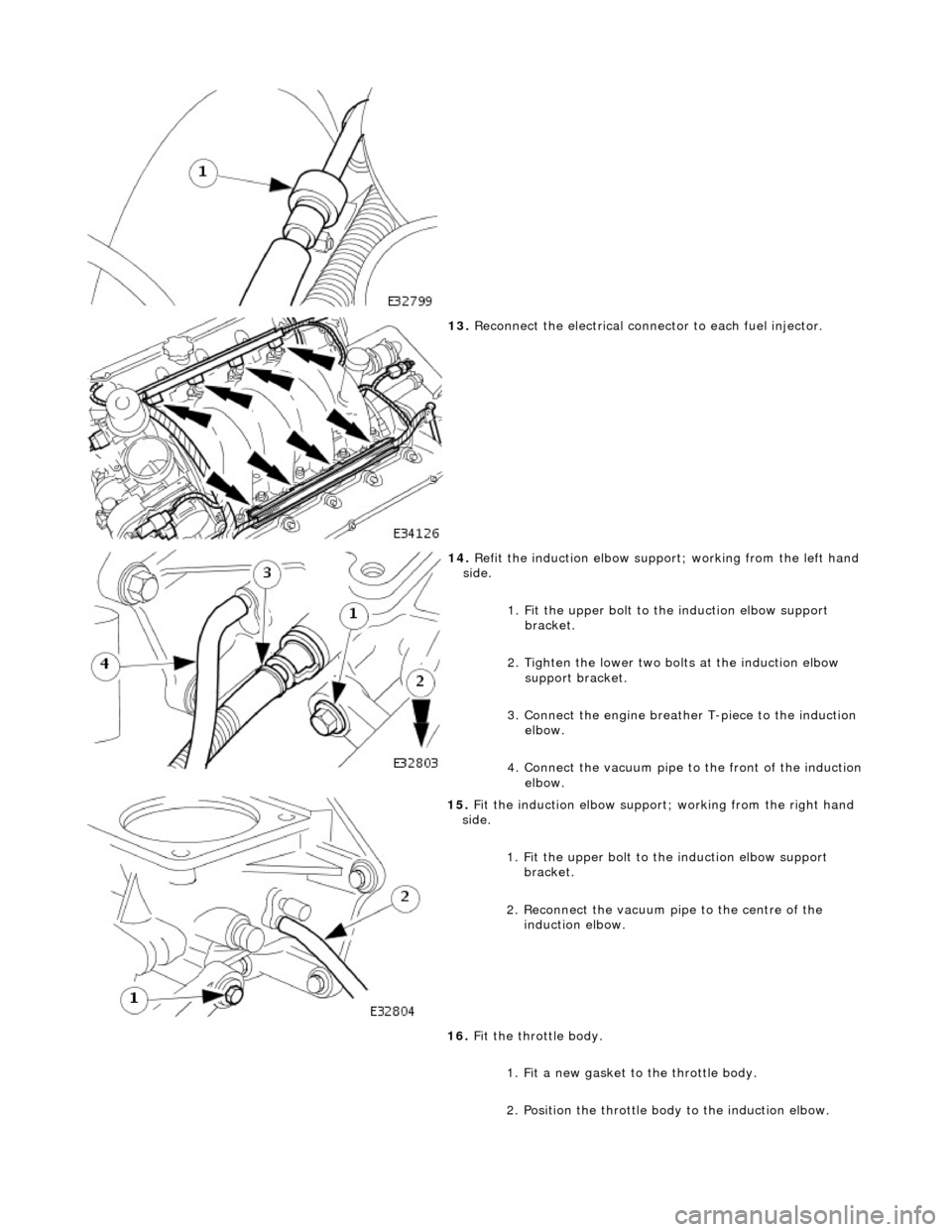
13. Reconnect the electrical connector to each fuel injector.
14. Refit the induction elbow support ; working from the left hand
side.
1. Fit the upper bolt to the induction elbow support
bracket.
2. Tighten the lower two bolts at the induction elbow support bracket.
3. Connect the engine breather T-piece to the induction elbow.
4. Connect the vacuum pipe to the front of the induction
elbow.
15. Fit the induction elbow support; working from the right hand
side.
1. Fit the upper bolt to the induction elbow support
bracket.
2. Reconnect the vacuum pi pe to the centre of the
induction elbow.
16. Fit the throttle body.
1. Fit a new gasket to the throttle body.
2. Position the throttle body to the induction elbow.
Page 722 of 2490
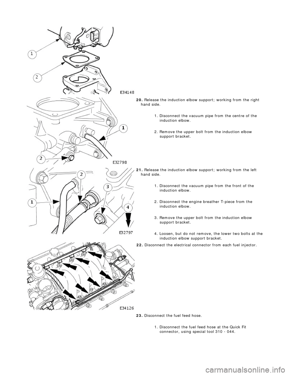
20. Release the induction elbow su pport; working from the right
hand side.
1. Disconnect the vacuum pi pe from the centre of the
induction elbow.
2. Remove the upper bolt from the induction elbow support bracket.
21. Release the induction elbow su pport; working from the left
hand side.
1. Disconnect the vacuum pipe from the front of the
induction elbow.
2. Disconnect the engine breather T-piece from the induction elbow.
3. Remove the upper bolt from the induction elbow support bracket.
4. Loosen, but do not remove , the lower two bolts at the
induction elbow support bracket.
22. Disconnect the electrical conne ctor from each fuel injector.
23. Disconnect the fuel feed hose.
1. Disconnect the fuel f eed hose at the Quick Fit
connector, using special tool 310 - 044.
Page 725 of 2490

7. Refit the induction elbow support ; working from the left hand
side.
1. Fit the upper bolt to the induction elbow support
bracket.
2. Tighten the lower two bolts at the induction elbow support bracket.
3. Connect the engine breather T-piece to the induction elbow.
4. Connect the vacuum pipe to the front of the induction
elbow.
8. Fit the induction elbow support; working from the right hand
side.
1. Fit the upper bolt to the induction elbow support
bracket.
2. Reconnect the vacuum pi pe to the centre of the
induction elbow.
9. Fit the throttle body.
1. Fit a new gasket to the throttle body.
2. Position the throttle body to the induction elbow.
10. Fit the throttle body securing bolts.
Page 751 of 2490
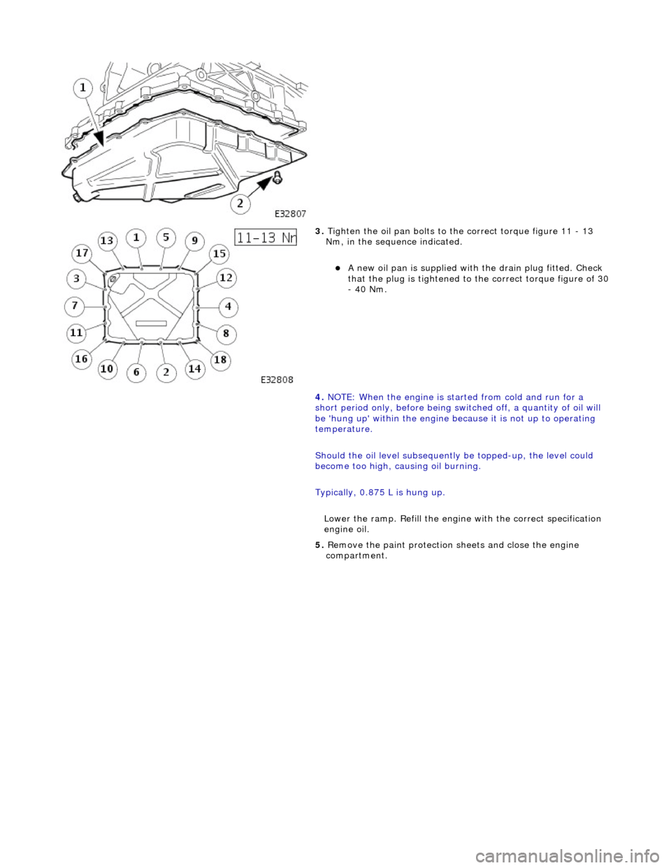
3. Tighten the oil pan bolts to the correct torque figure 11 - 13
Nm, in the sequence indicated.
A new oil pan is supplied with the drain plug fitted. Check
that the plug is tightened to the correct torque figure of 30 - 40 Nm.
4. NOTE: When the engine is star ted from cold and run for a
short period only, before being swit ched off, a quantity of oil will
be 'hung up' within the engine because it is not up to operating
temperature.
Should the oil level subsequently be topped-up, the level could
become too high, causing oil burning.
Typically, 0.875 L is hung up.
Lower the ramp. Refill the engine with the correct specification
engine oil.
5. Remove the paint protection sheets and close the engine
compartment.
Page 753 of 2490
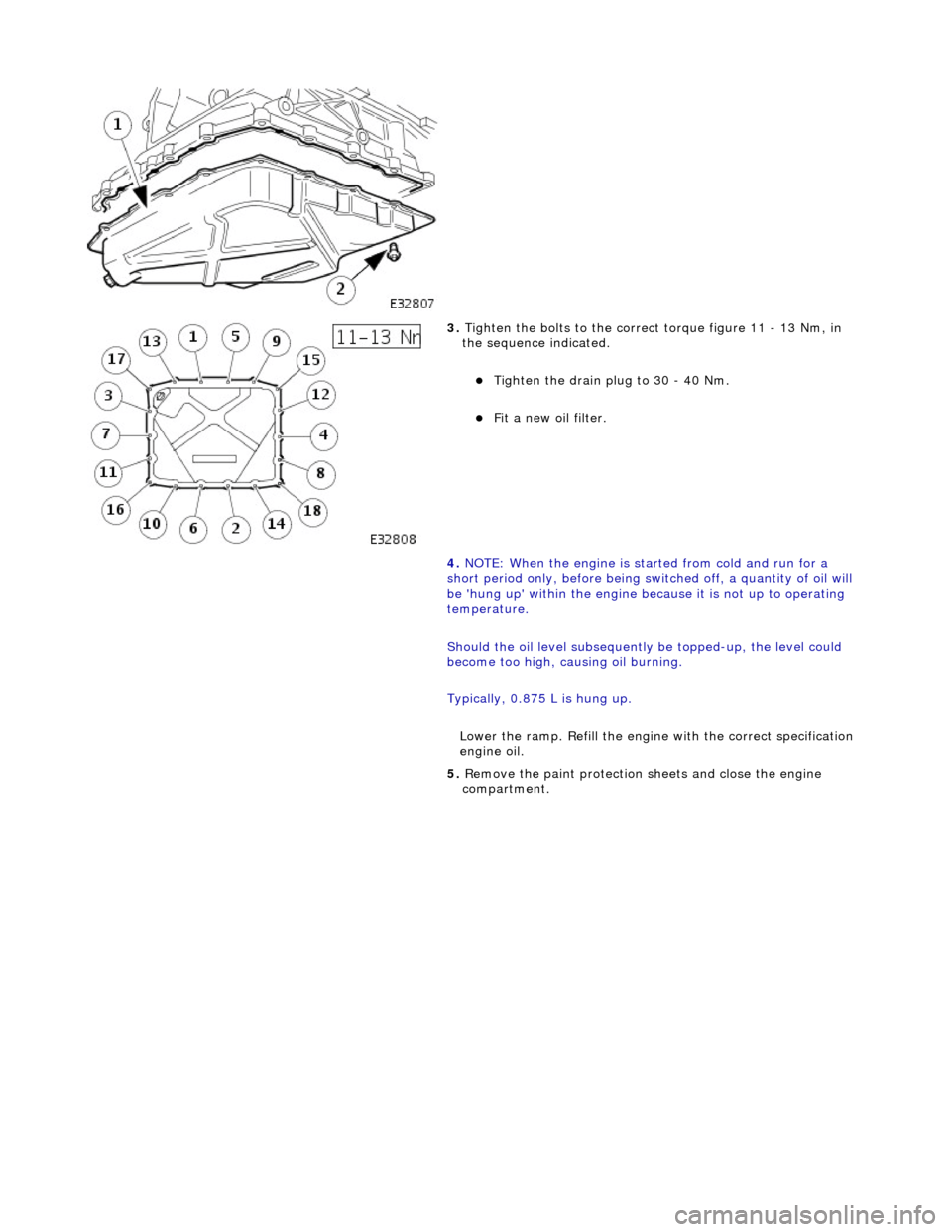
3. Tighten the bolts to the correct torque figure 11 - 13 Nm, in
the sequence indicated.
Tighten the drain plug to 30 - 40 Nm.
Fit a new oil filter.
4. NOTE: When the engine is star ted from cold and run for a
short period only, before being swit ched off, a quantity of oil will
be 'hung up' within the engine because it is not up to operating
temperature.
Should the oil level subsequently be topped-up, the level could
become too high, causing oil burning.
Typically, 0.875 L is hung up.
Lower the ramp. Refill the engine with the correct specification
engine oil.
5. Remove the paint protection sheets and close the engine
compartment.
Page 761 of 2490

2. Remove the access grommet (for torque converter bolts) from the housing.
11. Fit the damper securing bolt (old one) to the crankshaft,
hand-tight only.
12. Rotate the crankshaft until the triangular arrow indent on
the drive plate is visible thro ugh the access hole; confirm
that the timing flat on ea ch camshaft is uppermost.
13. Fit the crankshaft setting peg 303 - 531 to the crankshaft
position sensor location.
1. Fit the crankshaft setting peg 303 - 531.
1. Position the crankshaft so that the setting peg engages fully into the timing slot.
2. Fit and tighten the bolt to secure the setting peg.
14. Remove the damper securing bolt from the crankshaft.
15. Lower the vehicle on the ramp.
16. Fit the camshaft locking tool 303 - 530 to the A-Bank
camshafts, aligning the shafts slightly as necessary.
17. Loosen the bolt which secures the sprocket to the camshaft.
Page 768 of 2490
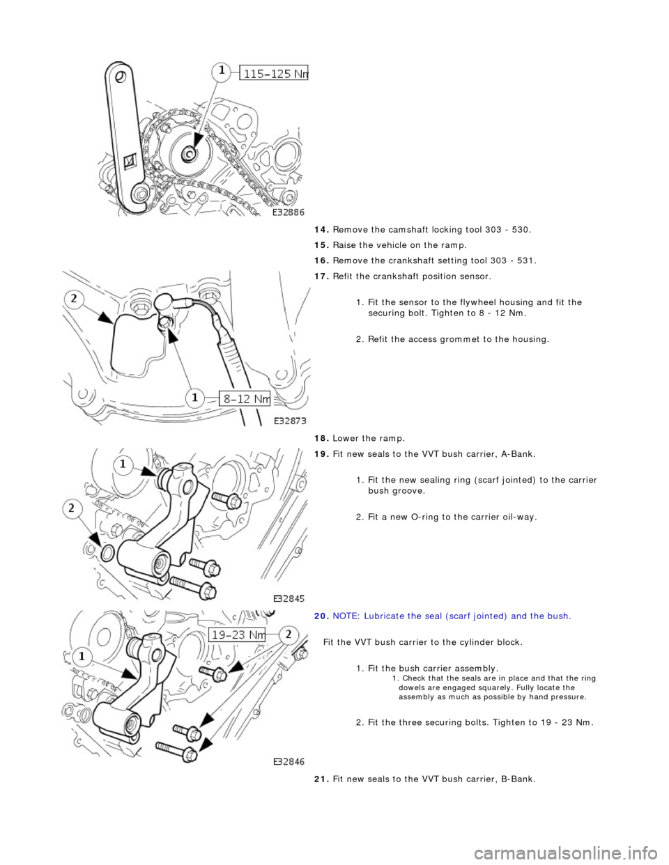
14. Remove the camshaft locking tool 303 - 530.
15. Raise the vehicle on the ramp.
16. Remove the crankshaft setting tool 303 - 531.
17. Refit the crankshaft position sensor.
1. Fit the sensor to the fl ywheel housing and fit the
securing bolt. Tighten to 8 - 12 Nm.
2. Refit the access grommet to the housing.
18. Lower the ramp.
19. Fit new seals to the VVT bush carrier, A-Bank.
1. Fit the new sealing ring ( scarf jointed) to the carrier
bush groove.
2. Fit a new O-ring to the carrier oil-way.
20. NOTE: Lubricate the seal (s carf jointed) and the bush.
Fit the VVT bush carrier to the cylinder block.
1. Fit the bush carrier assembly.
1. Check that the seals are in place and that the ring dowels are engaged squa rely. Fully locate the
assembly as much as possible by hand pressure.
2. Fit the three securing bolts. Tighten to 19 - 23 Nm.
21. Fit new seals to the VVT bush carrier, B-Bank.