lock JAGUAR X308 1998 2.G Workshop Manual
[x] Cancel search | Manufacturer: JAGUAR, Model Year: 1998, Model line: X308, Model: JAGUAR X308 1998 2.GPages: 2490, PDF Size: 69.81 MB
Page 625 of 2490

d
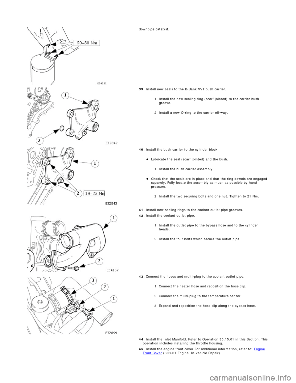
ownpipe catalyst.
39
.
Install new seals to the B-Bank VVT bush carrier.
1. Install the new sealing ring (scarf jointed) to the carrier bush groove.
2. Install a new O-ring to the carrier oil-way.
40
.
Install the bush carrier to the cylinder block.
Lu
bricate the seal (scarf
jointed) and the bush.
1. Install the bush carrier assembly.
Chec
k that the seals are
in place and that the ri ng dowels are engaged
squarely. Fully locate the assembly as much as possible by hand
pressure.
2. Install the two securing bolts and one nut. Tighten to 21 Nm.
41. Install new sealing rings to the coolant outlet pipe grooves.
42
.
Install the coolant outlet pipe.
1. Install the outlet pipe to the bypass hose and to the cylinder heads.
2. Install the four bolts which secure the outlet pipe.
43
.
Connect the hoses and multi-plug to the coolant outlet pipe.
1. Connect the heater hose and reposition the hose clip.
2. Connect the multi-plug to the temperature sensor.
3. Expand and reposition the hose clip along the bypass hose.
44. Install the Inlet Manifold. Refer to Operation 30.15.01 in this Section. This
operation includes installing the throttle housing.
45. Install the engine front cover.For additional information, refer to: Engine
Front Cover (303-01 Engi
ne, In-vehicle Repair).
Page 628 of 2490

7.
Remove the coolant outlet pipe.
1. Remove the four bolts which secure the outlet pipe.
2. Remove the outlet pipe from the bypass hose and from the cylinder heads.
8. Remove and discard the sealing ring s from the outlet pipe grooves.
9.
Remove the nuts which secure the catalytic converter to the A-Bank
exhaust manifold flange.
10 . Re
move the VVT bush carrier.
1. Remove the three bolts which secure the carrier to the cylinder block.
2. Release the carrier from the two ring dowels and remove it.
11. R
emove the seals from the bush carrier.
1. Remove the sealing ring (scarf jointed) from the carrier bush groove.
2. Remove the O-ring from the carrier oil-way recess.
12. Raise the vehicle on a ramp.
13. Remove the crankshaft position sensor.
Page 629 of 2490

• N
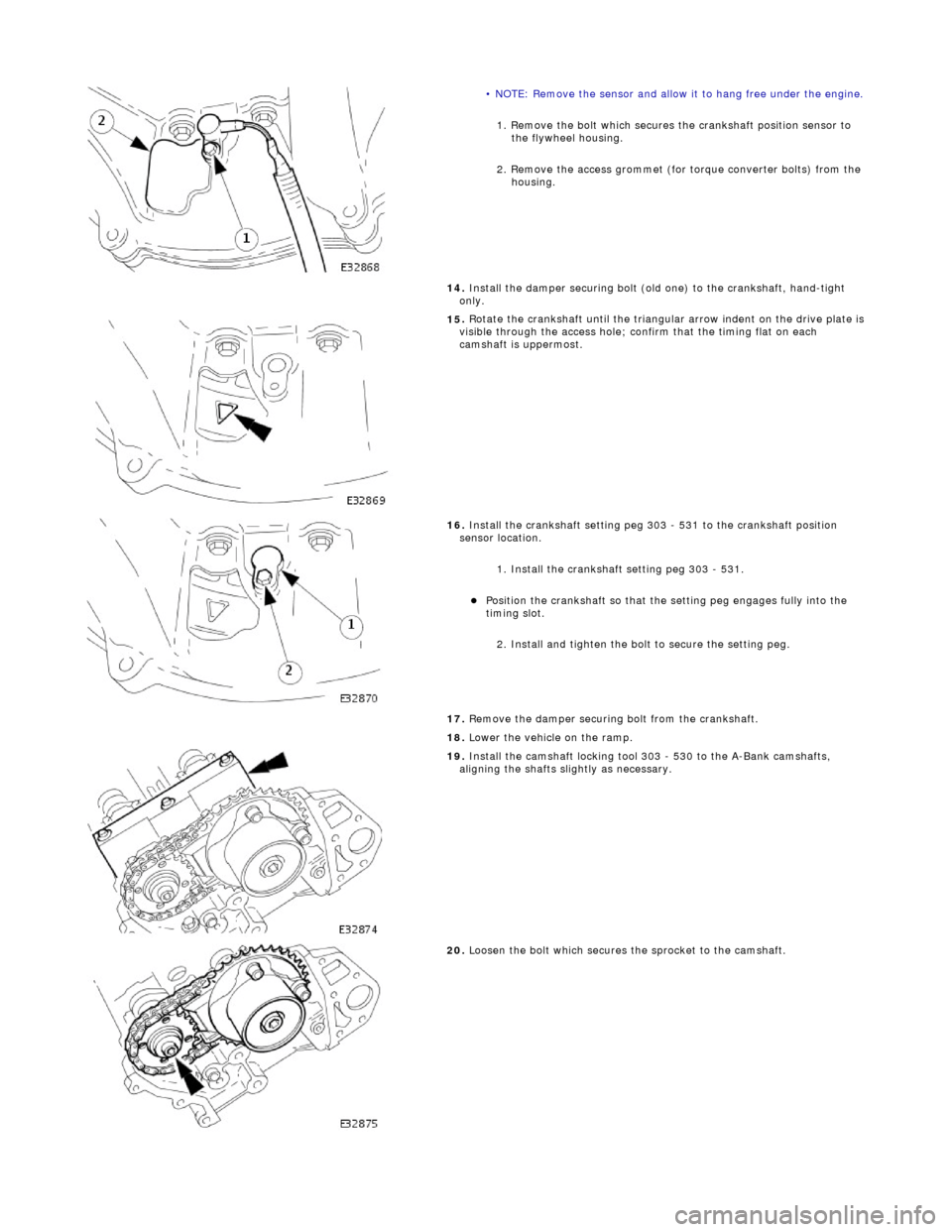
OTE: Remove the sensor and allow it to hang free under the engine.
1
. Remove the bolt which secures the crankshaft position sensor to
the flywheel housing.
2. Remove the access grommet (for torque converter bolts) from the housing.
14. Install the damper securing bolt (old one) to the crankshaft, hand-tight
only.
15
.
Rotate the crankshaft until the triangular arrow indent on the drive plate is
visible through the access hole; confirm that the timing flat on each
camshaft is uppermost.
16
.
Install the crankshaft setting peg 3 03 - 531 to the crankshaft position
sensor location.
1. Install the crankshaft setting peg 303 - 531.
Position
the crankshaft so that the setting peg engages fully into the
timing slot.
2. Install and tighten the bolt to secure the setting peg.
17. Remove the damper securing bolt from the crankshaft.
18. Lower the vehicle on the ramp.
19
.
Install the camshaft locking tool 303 - 530 to the A-Bank camshafts,
aligning the shafts slightly as necessary.
20
.
Loosen the bolt which secures the sprocket to the camshaft.
Page 630 of 2490

21. L
oosen the bolt which secures the VVT unit to the camshaft.
22. Remove the camshaft locking tool 303 - 530 (installed for previous
operation).
23. R
emove the primary chain tensioner bolts.
24 . R
emove the tensioner assembly.
1. Remove the tensioner.
2. Remove the tens ioner back-plate.
25 . R
emove the primary chain tensioner blade.
1. Remove the pivot bolt which secures the tensioner blade.
2. Remove the tensioner blade.
26. Remove the primary chain from the VVT unit and from the crankshaft
pulley.
27 . R
emove the VVT unit and exhaust camshaft sprocket.
1. Remove the securing bolt from both the VVT unit and the exhaust cam sprocket.
2. Remove the VVT unit, exhaust sprocket and secondary chain as an assembly (release the chain from the tensioner which is still
secured to the cylinder head).
Re
move the secondary chain from
the VVT unit and the sprocket.
28. Remove the secondary chain tensioner.
Page 632 of 2490

Installation
hea
d.
3. With assistance, remove the cylinder head.
34 . R
emove the cylinder head gasket.
1. Note how the gasket is installed and remove it.
2. Remove and discard the cloth, placed previously to absorb coolant spillage.
Wipe up any l e
aked coolant.
35. Remove the coolant drain tray from under the engine.
36. Remove and discard the gasket from the downpipe catalyst.
Cle
an the gasket faces of the catalyst and the exhaust manifold.
37. Clean cylinder head and cylinder block gasket faces.
Ensu
re that all threaded holes in the cylinder block face are clean and
free from oil.
Cl ean and
inspect the cylinder head bolts. They may be re-used on two
occasions. When re- used, each bolt head should be marked with one
dot from an automatic centre punch.
38. Clean and inspect all relevant components and mating faces.
1. CAUTIONS: If a replacement cylinder head is to be installed to a vehicle with VCT
the cylinder head must have the oil gallery blind rivet removed before
installation.
Make sure that all debris is removed from the cylinder head and cylinder
head oil gallery.
Vehicles fitted with VCT: Remove the blind rivet from the VCT oil gallary. • NOTE: The centre bore of the blind rivet is 6 mm diameter.
Page 633 of 2490

I
dentify the VCT oil supply gallery and the 8 mm blind rivet.
U
sing a suitable 3 mm punch release the centre of the blind rivet until
it is released from the outer part of the blind rivet.
U
sing a suitable extraction tool, remo
ve the remaining part of the blind
rivet.
2. Clean the component mating faces.
3.
Check cylinder head face for distortio
n, across the center and from corner
to corner.
4. For cylinder head face distortion data, refer to specifications.For additional
information, refer to: Specifications
(303
-00 Engine System - General
Information, Specifications).
5.
NOTE: For
cylinder head with
distortion above the
maximum allowance,
the cylinder head
material must be
measured.
Measure the
cylinder head
material.
Che
ck
measurement
from the
centre of the
exhaust
dowel to the
cylinder head
face as
shown.
If the
measurement
is less than
51.88 mm
the cylinder
head requires
replacement.
6.
Install a new gasket to the downpipe catalyst flange.
7. Install and align a new cylinder head gasket to the cylinder block face.
Page 634 of 2490

8.
With assistance, install the cylinder head.
Engage t
he cylinder head with the dowels on the block face, and the
exhaust manifold flange with the studs on the downpipe catalyst.
9. Install the cylinder head bolts, hand tight only.
10 . Ti
ghten the cylinder head bolts in stages, in the sequence shown, using
the following procedure:
Stage 1 - ti
ghten all M10 bolt
s in sequence, to 20 Nm.
11. Stage 2 - tighten all M10 bolt s in sequence, to 35 Nm.
Page 637 of 2490

To th
e upper face of each bearing surface (two places) in the cylinder
head.
To th
e upper face of each bearing surface (two places) in each bearing
cap.
On
the cam lobes ONLY, not on the base circle area.
17
.
Install the camshafts.
1. Install the camshafts to position in the cylinder head, with the timing flats uppermost.
2. Install the camshaft caps to their respective locations (inlet 0 to 4 and exhaust 5 to 9 from the front) and in the correct orientation
(arrow to front of engine).
3. Install and tighten the cap securing bolts. Tighten evenly, in stages, to 10 Nm.
18. Install the camshaft locking tool 303 - 530, align the camshafts as
necessary.
19
.
Install the chain guide.
• NOTE: The chain guide must be installed so that the slotted hole is
towards the top, and the raised shoulder to the cylinder block. 1. Install the chain guide to the block and locate it onto the upper retaining pin.
2. Install the retaining bolt and tighten it to 12 Nm.
20
.
Push the secondary chain tensioner piston into the body to provide
clearance for installing the chain.
1. Insert a thin rigid wire through the hole in the end of the tensioner
piston to displace the ball from the non-return valve seat.
2. With the wire in position, press the piston fully into the tensioner body.
Re
move the wire.
21
.
Install the secondary chain tensioner to the engine.
1. Fully seat the tensioner to the cylinder head.
2. Install the two bolts which secure the tensioner and tighten to 12 Nm.
22. Install the VVT unit to the engine.
A
ssemble the VVT unit, the exhaust camshaft sprocket and the
Page 638 of 2490

se
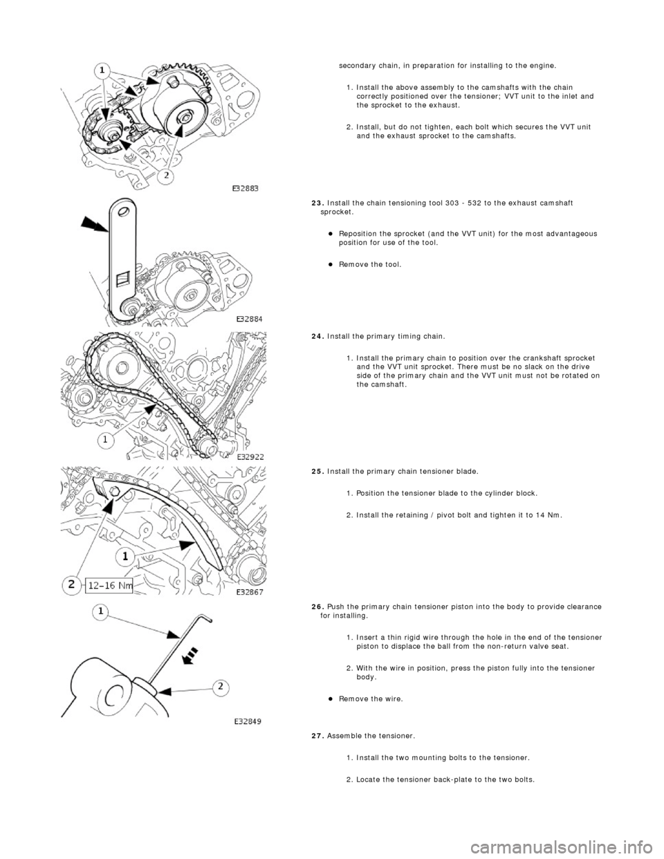
condary chain, in preparation for installing to the engine.
1. Install the above assembly to the camshafts with the chain correctly positioned over the tensioner; VVT unit to the inlet and
the sprocket to the exhaust.
2. Install, but do not tighten, each bolt which secures the VVT unit and the exhaust sprocket to the camshafts.
23 .
Install the chain t
ensioning tool 303 - 532 to the exhaust camshaft
sprocket.
Re p
osition the sprocket (and the VVT unit) for the most advantageous
position for use of the tool.
Re
move the tool.
24 . Install the
primary timing chain.
1. Install the primary chain to position over the crankshaft sprocket and the VVT unit sprocket. There mu st be no slack on the drive
side of the primary chain and the VVT unit must not be rotated on
the camshaft.
25 . Install the pri
mary chain tensioner blade.
1. Position the tensioner blade to the cylinder block.
2. Install the retaining / pivot bolt and tighten it to 14 Nm.
26 . P
ush the primary chain tensioner piston into the body to provide clearance
for installing.
1. Insert a thin rigid wire through the hole in the end of the tensioner
piston to displace the ball from the non-return valve seat.
2. With the wire in position, press the piston fully into the tensioner body.
Rem
ove the wire.
27. Assemble the tensioner.
1. Install the two mounting bolts to the tensioner.
2. Locate the tensioner back-plate to the two bolts.
Page 639 of 2490

28
.
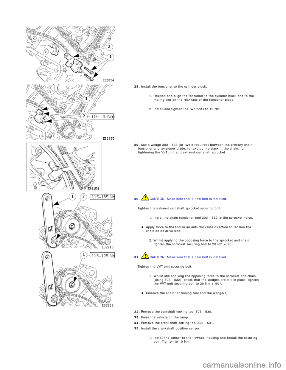
Install the tensioner to the cylinder block.
1. Position and align the tensioner to the cylinder block and to the mating slot on the rear face of the tensioner blade.
2. Install and tighten the two bolts to 12 Nm.
29
.
Use a wedge 303 - 533 (or two if required) between the primary chain
tensioner and tensioner blade, to ta ke up the slack in the chain, for
tightening the VVT unit and exhaust camshaft sprocket.
30
.
CAUTION: Make sure that a new bolt is installed.
Tighten the exhaust camshaft sprocket securing bolt. 1. Instal the chain tensioner t ool 303 - 532 to the sprocket holes.
Appl
y force to the tool in an anti
-clockwise direction to tension the
chain on its drive side.
2. Whilst applying the opposing force to the sprocket and chain, tighten the sprocket securing bolt to 20 Nm + 90°.
31
.
CAUTION: Make sure that a new bolt is installed.
Tighten the VVT unit securing bolt. 1. Whilst still applying the opposing force to the sprocket and chain (using 303 - 532), check that the wedges are still in place, tighten
the VVT unit securing bolt to 20 Nm + 90°.
R
emove the chain tensioning tool and the wedge(s).
32
.
Remove the camshaft locking tool 303 - 530.
33. Raise the vehicle on the ramp.
34. Remove the crankshaft setting tool 303 - 531.
35. Install the crankshaft position sensor.
1. Install the sensor to the flywheel housing and Install the securing bolt. Tighten to 10 Nm.