501 JAGUAR X308 1998 2.G Workshop Manual
[x] Cancel search | Manufacturer: JAGUAR, Model Year: 1998, Model line: X308, Model: JAGUAR X308 1998 2.GPages: 2490, PDF Size: 69.81 MB
Page 27 of 2490

419:
Electronic Featu r
e
Group
419
‐10:
Multifunction Electronic Modules
Removal
and Installation
Driver
Seat Module (DSM) (86.75.28)
5: Body and Paint
501: Body and Paint
501‐00: Body System ‐ Gen
eral Information
Specification
Description and Operation
Body
501‐02: Front End Body Panels
Description and Operation
Front End Body Panels
Removal and Installation
Cowl Panel Grille (76.10.01) (76.43.39)
Driver Side Bulkhead Cover (76.11.34)
Passenger Side Bulkhead Cover (76.11.33)
Radiator Grille Opening Panel (76.10.06)
Radiator Grille Ope
ning Panel Reinforcement (76.11.24)
Radiator Splash Shield (76.22.90)
501‐03: Body Closures
Description and Operation
Body Closures
General Procedures
Hood Alignment (76.16.02)
Diagnosi
s
and Testing
(FDM)
Front
Door Module
(86.80.34)
Rear
(RDM)
Door
Module
Page 28 of 2490

Removal and Installation
Door (76. 28.04)
Front Doo
r
Opening Weatherstrip (76.40.01)
Fuel Filler Door (76.10.25)
Hood (76.16.01)
Hood Hinge (76.16.12)
Hood Striker (76.16.24)
Hood Strut (76.16.15)
Luggage Compartment Lid Hinge (76.19.28)
Luggage Compartment Lid Opening Weatherstrip (76.19.06)
Luggage Compartment Lid Striker (76.19.12)
Luggage Compartment Lid Strut (76.19.27)
Rear Door Opening Weathe
rstrip (76.40.02)
501‐05: Interior Trim and Ornamentation
Description and Operation
Interior Trim
Removal and Installation
A‐Pillar Trim Panel (76.13.31)
B‐Pillar Trim Panel (76.13.28)
Cowl Side Trim Panel (76.13.30)
C‐Pillar Trim Panel (76.13.73)
Door Window Control Switch Finish Pane
l (76.47.33)
Engine Cover (76.11.35)
Floor Covering (76.49.08)
Folding Tray (76.47.31)
Folding Tray Finish Panel (76.47.32)
Front Door Armrest (76.34.22)
Front Door Trim Panel Finish Panel (76.47.11)
Front Door Stowage Compartment (76.34.27)
Front Door Trim Panel (76.34.01)
Headliner (76.64.01)
Luggage Compartment Front Trim Panel (76.19.31)
Luggage Compart
ment Lid Trim Panel (76.19.05)
Luggage Compartment Rear Trim Panel (76.19.44)
Luggage Compartment Side Trim Panel (76.19.22)
Overhead Console Finish Panel (76.47.41)
Page 29 of 2490

Parcel Shelf (76.67. 06)
Parcel Shelf
Support (76.67.09)
Passenger Assist Handle (76.58.30)
Rear Door Armrest (76.34.23)
Rear Door Trim Panel Finish Panel (76.47.12)
Rear Door Trim Panel (76.34.04)
Rear Window Blind (76.14.04)
Rear Door Window Control Switch Finish Panel (76.47.34)
Scuff Plate Trim Panel (76.13.81)
Sun Visor (76.10.48)
501‐08: Exterior Trim and Or
namentation
Description and Operation
Exterior Trim
Removal and Installation
A‐Pillar Moulding LH (76.13.19)
A‐Pillar Moulding RH (76.13.20)
Coachlines
Door Moulding (76.43.72)
Front Fender Moulding (76.10.48) (76.43.73)
Luggage Compartment Lid Badges (76.44.03)
Luggage Compartment Lid Moulding (76.43.79)
Radiator Grille (76.
55.03)
Radiator Grille Bezel (76.55.15)
501‐09: Rear View Mirrors
Description and Operation
Rear View Mirrors
Removal and Installation
Auto‐Dimming Interior Mirror (76.10.56)
Exterior Mirror (76.10.52)
Exterior Mirror Cover (76.10.55)
Exterior Mirror Glass (76.10.53)
Exterior Mirror Motor (76.10.57) (76.11.09)
Interior Mirror (76.10.51)
Interior Mirro
r Mounting Block (76.10.62)
Page 30 of 2490

501‐10: Seating
Specificatio
n
Description and Operation
Seats
Removal and Installation
Front Seat (76.70.01)
Front Seat Backrest (76.70.06)
Front Seat Backrest Cover (76.70.15)
Front Seat Backrest Heater Mat (86.75.14)
Front Seat Backrest Trim Panel (76.70.03)
Front Seat Cushion (76.70.11)
Front Seat Cushion Cover (76.70.33)
Front Sea
t Cushion Heater Mat (86.75.13)
Front Seat Head Restraint (76.70.14)
Front Seat Head Restraint Motor (86.75.17)
Front Seat Recliner Motor (86.75.04)
Front Seat Track (76.70.20)
Front Seat Track Motor (86.75.33)
Lumbar Motor (86.75.12)
Rear Seat Armrest (76.70.39)
Rear Seat Backrest (76.70.38)
Rear Seat Backrest Cover (76.70.48) (78.90.12)
Rear Seat Backrest Heater Mat (86.75.35)
Rear Seat Cushio
n (76.70.37)
Rear Seat Cushion Cover (76.70.47)
Rear Seat Cushion Heater Mat (86.75.37)
Rear Seat Head Restraint (76.70.56)
Rear Seat Track
Seat Control Switch (86.75.23)
501‐11: Glass, Frames and Mechanisms
Description and Operation
Glass, Fra
mes and Mechanisms
Removal and Installation
Door Window Control Switch Bulb (86.46.12)
Front Door Window Glass (76.31.01)
Front Door Window Glass Weatherstrip (76.40.28)
Page 31 of 2490

Front Doo r
Window Regulator and Motor (76.31.45)
Front Door Window Regulator Motor (76.31.45)
Front Door Window Control Switch (86.25.07)
Rear Door Window Glass (76.31.02)
Rear Door Window Glass Weatherstrip (76.40.29)
Rear Door Window Regulator and Motor (86.25.09)
Rear Door Window Regulator Motor (86.25.09)
Rear Door Window Control Swi
tch (86.25.10)
Rear Quarter Window Glass (76.31.31)
Rear Window Glass (76.81.11)
Windshield Glass (76.81.40)
501‐12: Instrument Panel and Console
Specification
Description and Operation
Instrument Panel and Instrument Panel Console
Removal and Installation
Audio Unit Housing (76.25.15)
Climate Control Assembly Housing
Coin Stowage Compartment (76.46.37)
Floor Co
nsole (76.25.01)
Floor Console Ashtray (76.25.25)
Floor Console Extension (76.25.05)
Floor Console Finish Panel (76.47.26)
Floor Console Finish Panel Bracket (76.25.26)
Floor Console Stowage Compartment (76.25.16)
Floor Console Stowage Compartment Lid (76.25.18)
Glove Compartment (76.52.03)
Glove Compartment Lid (76.52.02)
Glove Compartment Lid Damper (76.52.22)
Glove Co
mpartment Liner (76.52.21)
Instrument Cluster Finish Panel (76.47.24)
Instrument Cluster Finish Panel Bezel (88.20.33)
Instrument Panel (76.46.01)
Instrument Panel Finish Panel (76.47.06)
Instrument Panel Lower Trim Panel (76.46.11)
Overhead Console (76.13.69)
Page 32 of 2490

Rear Cup Holder (76.25.27)
Steering Col u
mn
Lower Shroud (76.46.03)
Steering Column Upper Shroud (76.46.02)
501‐14: Handles, Locks, Latches and Entry Systems
Description and Operation
Handles, Locks, Latches and Entry Systems
Removal and Installation
Exterior Driver Door Handle (76.58.07)
Driver Door Latch (76.37.74)
Glove Compartment Lid Ha
ndle (76.52.08)
Glove Compartment Lid Lock Cylinder (76.52.23)
Luggage Compartment Lid Latch (76.19.25)
Luggage Compartment Lid Latch Actuator (76.19.25)
Luggage Compartment Lid Release Switch (86.25.56)
Luggage Compartment Lid Warning Indicator Switch (86.65.93)
Exterior Passenger Door Handle (76.58.08)
Passenger Door Latch (76.37.75)
Exterior Rear Door Handle (76.58.02)
Rear Door Latch (76.37.09)
501‐16: Wipers and Washers
Descriptio
n and Operation
Wipers and Washers
Removal and Installation
Headlamp Washer Jet (84.20.08)
Headlamp Washer Pump (84.20.21)
Rain Sensor (84.12.10) (86.56.62)
Windshield Washer Pump (84.10.21)
Windshield Washer Reservoir (84.10.01) (84.10.03)
Windshield Wiper Motor (84.15.13)
Windshield Wiper/
Washer Switch (86.65.42)
Wiper Pivot Arm (84.15.03)
Page 33 of 2490

501‐17: Roof Open
ing
Panel
Description and Operation
Roof Opening Panel
General Procedures
Motor Synchronization (76.82.48)
Roof Opening Panel Alignment
Removal and Installation
Roof Opening Panel (76.82.05)
Roof Opening Panel Frame (76.82.01)
Roof Opening Panel Module (86.76.07)
Roof Opening Panel Motor (86.76.01)
Roof Opening Panel Shie
ld (76.82.06)
Roof Opening Panel Trim
Roof Opening Panel Weatherstrip (76.82.15)
501‐19: Bumpers
Specification
Description and Operation
Bumpers
Removal and Installation
Front Bumper (76.22.08)
Front Bumper and Bumper Cover (76.22.08)
Front Bumper Cover (76.22.78)
Front Bumper Isolator (76.22.31)
Rear Bumper (76.22.27) (76.22.52)
Rear Bumper Co
ver (76.22.74) (76.22.77)
Rear Bumper Isolator (76.22.70)
501‐20A : Safety Belt System
Specification
Description and Operation
Safety Belt System
Removal and Installation
Front Safety Belt Retractor (76.73.10)
Rear Safety Belt Retractor (76.73.18)
Safety Belt Shoulder Height Adjuster (76.73.12)
Page 34 of 2490

501‐20B : Supp l
emental
Restraint System
Specification
Description and Operation
Air Bag Supplemental Restraint System (SRS)
Removal and Installation
Air Bag Control Module (76.73.41)
Driver Air Bag Module (76.73.39)
Passenger Air Bag Module (76.73.37)
Side Air Bag Module (76.73.47)
Side Impact Sensor (76.73.53)
501‐25: Body Repairs ‐ Genera
l Information
Description and Operation
Body Repairs
502: Frame and Mounting
502‐00: Uni ‐Body, Subframe and Mounting System
Removal and Installation
Front Axle Crossmember
Front Axle Crossmember Front Bushing (60.35.24)
Front Axle Crossmember Front Bushing Heat Shield (60.35.37)
Front Axle Crossmember Rear Bushing (
60.35.26)
Rear Axle Crossmember (64.25.16)
Rear Axle Crossmember Bushing (64.25.02)
Page 505 of 2490

Steering Column - Steering Column
Description an
d Operation
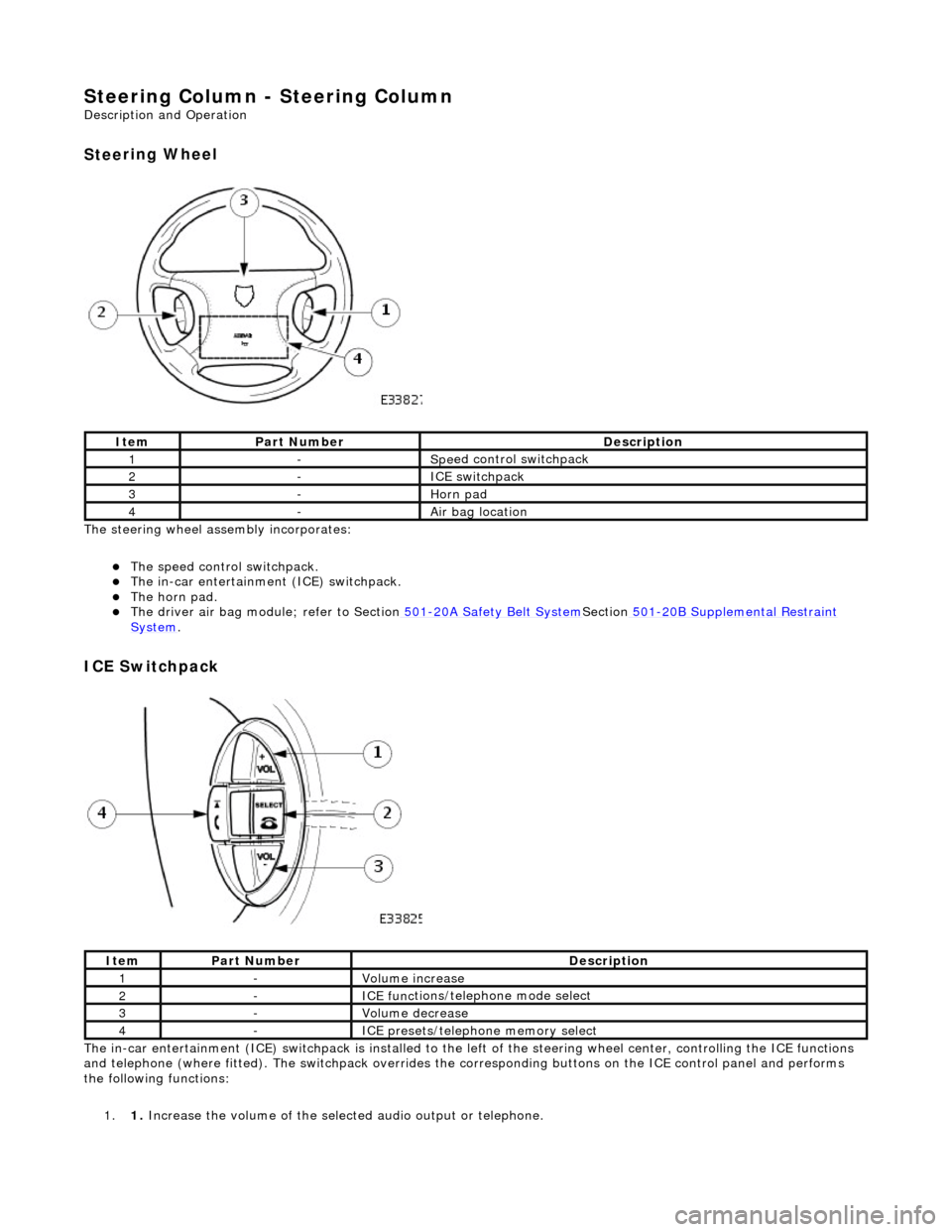
Stee
ring Wheel
T
he steering wheel assembly incorporates:
The s
peed control switchpack.
The i
n-car entertainment (ICE) switchpack.
The h
orn pad.
The driver ai
r bag module; refer to Section
501
-20A Safety Belt
System
Sectio
n
501
-2
0B Supplemental Restraint
Sy
stem
.
I
CE Switchpack
The
in-car entertainment (ICE) switchpack is installed to the le
ft of the steering wheel center, controlling the ICE functions
and telephone (where fitted). The switchpack overrides the corresponding bu ttons on the ICE control panel and performs
the following functions:
1. 1. Increase the volume of the select ed audio output or telephone.
It
em
Par
t Number
De
scription
1-Spe
ed control switchpack
2-I
CE switchpack
3-Horn pad
4-Air bag lo
cation
It
em
Par
t Number
De
scription
1-Vol
ume increase
2-ICE func
tions/teleph
one mode select
3-Volum
e decrease
4-ICE pres
ets/telephone memory select
Page 507 of 2490

The driver air bag is moun
ted below the horn operat
ing pad area, adjacent to the steering wheel hub.
For air bag safety and service information, refer to Section 501
-20A Safety Belt
System
Sectio
n
501
-2
0B Supplemental
Re
straint System
.
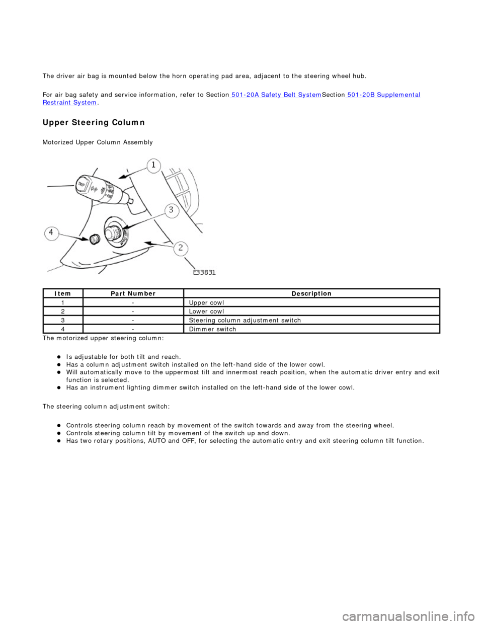
Upper Steering Column
Motorized Upper Colu
mn Assembly
The motorized upper steering column:
Is adjustable for both til
t and reach.
Has a col
umn adjustment switch installed on
the left-hand side of the lower cowl.
W
ill automatically move to the uppermost tilt and innermost reach position, when the automatic driver entry and exit
function is selected.
Has an instrument li
ghti
ng dimmer switch installed on the left-hand side of the lower cowl.
The steering column adjustment switch:
Controls steeri
ng column reach by
movement of the switch towards an d away from the steering wheel.
Controls steeri
ng column tilt by mo
vement of the switch up and down.
Has two
rotary positions, AUTO and OFF, for selecting the
automatic entry and exit steering column tilt function.
It
em
Par
t Number
De
scription
1-Upper
cowl
2-Lower cowl
3-Ste
ering column adjustment switch
4-Di
mmer switch