abs JAGUAR X308 1998 2.G User Guide
[x] Cancel search | Manufacturer: JAGUAR, Model Year: 1998, Model line: X308, Model: JAGUAR X308 1998 2.GPages: 2490, PDF Size: 69.81 MB
Page 70 of 2490
Upper
Wishbones
Each
upper wi
shbone assembly is a on
e-piece steel forging incorporating:
A pres
s-fit ball joint.
Press-fi
t bushes for location of the upper fulcrum bolt.
Lower Wishbones
Each l
o
wer wishbone comprising
forged steel front and rear arms bolted together, incorporates:
A p
ress-fit ball joint in the outer extremity of the rear arm.
Press-f
i
t bushes for location of the lower fulcrum bolts
Locati
on for the shock absor
b
er lower mounting plates.
Vertica l Links
The vertical
links are of forged steel
wi
th integral steering arms. Each is suppo rted between the upper and lower wishbones
by two ball joints and carries:
Front hub
Brake ca
liper and disc shield assembly
ABS se
nsor
.
Front Hub
s
Each f
o
rged steel front hub accommodates sealed for life cartridge
type wheel bearings, and carries:
The brake rotor assembl
y.
A
h
ub nut with toothed, integral ABS rotor.
Su
s
pension spring pi
n locking device.
Front Road
Springs
The road spri
ng
s are of coil type with their
rating dependent upon vehicle specification
Ea
ch spring is installed between the suspension crossbeam location and the lower wishbone spring pan.
Ru
bber seats ar
e installed betw
een the spring and the crossb eam and the spring pan.
Front Shock A
bsorbers
Th
e
shock absorbers are telescopic hydrau
lically operated units. Optional adaptive damping units incorporate a solenoid-
operated control valve at their upper extremity.
Each shoc
k absorber is installed between the lowe
r wishbone rear arm and a recess in the body.
The l
o
wer end of the shock absorber is se
cured to plates on the wishbone by a bolt that also serves as a pivot.
The u
pper en
d of each shock absorber is secured to the body location by a single nut.
Front Sta
b
ilizer Bar
A
front stabil
izer bar installed on all vehicles
is rated according to suspension specification.
Opera
tion
As each road wheel r
i
ses, move
ment is transmitted through the vertical link assembly to the lower wishbone. The resulting
rise of the wishbone compresses the road spring and partially telescopes the shock absorber. During this action, the spring
absorbs associated shocks and the shock absorber minimizes sprin
g os c
illation.
Du
ring cornering, vehicle weight
is transferred to the outer road wheel with a resulting tendency for the inner wheel to lift.
The stabilizer bar assists in minimizing this tendency by transf erring a proportion of potential lift of the inner wheel to the
outer wheel. This result s in enhanced body stability with improved corner ing capabilities.
Page 82 of 2490

1.
Install special tool 204-293 on ball joint.
2. Tighten tool bolt to rele ase ball joint taper pin from
vertical link.
20. Remove special tool 204-293 from ball joint.
21 . R
emove vertical link/hub assembly.
Support
ing ver
tical link/ hu
b assembly, remove lower
wishbone ball joint nut.
R e
move vertical link /hub assembly.
22 . R
emove stabilizer bar link to
wishbone securing nut and bolt.
23 . R
emove wishbone front arm to
rear arm securing bolt .
24. Slacken but do not remove shock absorber lower nut and
bolt.
Page 85 of 2490

1
. Install nut and bolt and tighten to 22-28Nm.
4. Position an
d connect harnes
s to steering transducer.
RHD
vehicles. Position steeri
ng harness behind return
pipe.
Conne
ct harness to transducer.
5. Secure return pipe on steering
rack.
1. Position pipe rubber support on steering rack.
2. Position pipe on support .
3. RHD vehicles. Position harness on pipe support rubber.
4. Secure pipe and harness to support with new tiestrap.
6. Inst
all shock absorber
and mounting bracket.
Posit
ion shock absorber moun
ting bracket on wishbone
rear arm.
Install
wishbone front arm to
rear arm bolt and tighten to
77-103Nm.
7. Tighten shock absorber lower bolt and nut to 43-57Nm.
Page 95 of 2490
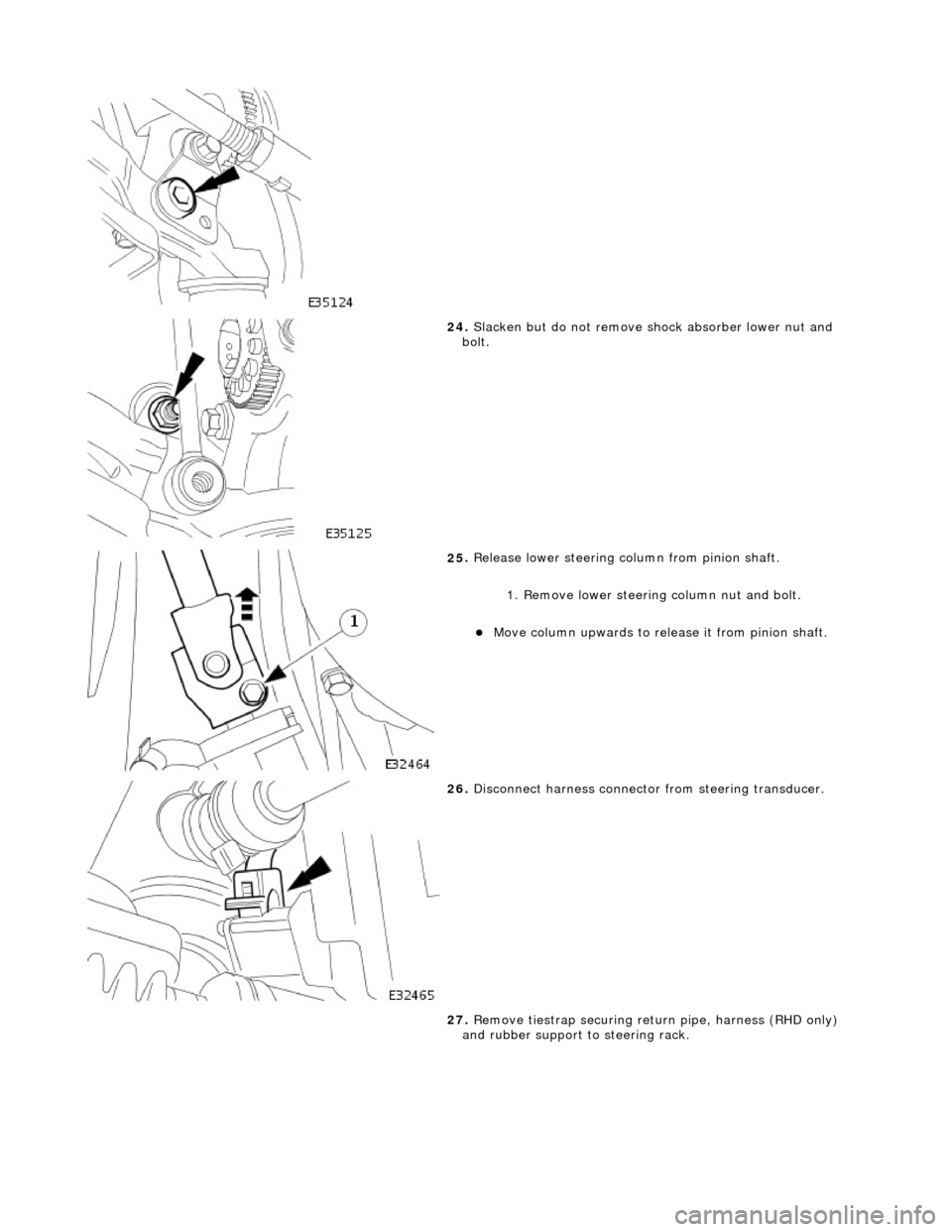
24
.
Slacken but do not remove shock absorber lower nut and
bolt.
25
.
Release lower steering column from pinion shaft.
1. Remove lower steering column nut and bolt.
Move column up
wards to release it from pinion shaft.
26
.
Disconnect harness connector from steering transducer.
27. Remove tiestrap securing retu rn pipe, harness (RHD only)
and rubber support to steering rack.
Page 99 of 2490

4
. Secure pipe and harnes
s(RHD vehicles) to support
with new tiestrap.
8. Posi
tion wishbone front arm on crossbeam and install but do
not tighten eccentric bolt and nut.
9. Inst
all shock absorber mounting bracket.
Posit
ion shock absorber moun
ting bracket on wishbone
rear arm.
Install
wishbone front arm to
rear arm securing bolt and
tighten to 77-103Nm.
10
.
Install stabilizer bar link to wi shbone bracket nut and bolt and
tighten to 41-54Nm.
11. Tighten shock absorber lowe r bolt and nut to 43-57Nm.
Page 105 of 2490
Front Suspension - Fron
t Shock Absorber
Re
moval and Installation
Remov
al
S
pecial Tool(s)
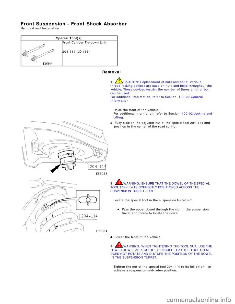
Front Camber Tie-do
wn Link
204-114 (JD 133)
1. CAUTION: Replacement of nuts and bolts: Various
thread-locking devices are used on nuts and bolts throughout the
vehicle. These devices restrict the number of times a nut or bolt
can be used.
For additional informat ion, refer to Section 100
-0
0 General
Informati
on
.
R
aise the front of the vehicle.
For additional informat ion, refer to Section 100
-0
2 Jacking and
Liftin
g
.
2.
Ful
ly slacken the adjuster nut of the special tool 204-114 and
position in the center of the road spring.
3. W
ARNING: ENSURE THAT THE DOWEL OF THE SPECIAL
TOOL 204-114 IS CORRECTLY POSITIONED ACROSS THE
SUSPENSION TURRET SLOT.
Locate the special tool in the suspension turret slot.
Pass
the upper dowel through the slot in the suspension
turret and rotate to locate the dowel.
4. Lower the front o
f
the vehicle.
5. WARNING: WHEN TIGHTENING THE TOOL NUT, USE THE
LOWER DOWEL AS A GUIDE TO ENSURE THAT THE TOOL STEM
DOES NOT ROTATE AND DISTURB THE POSITION OF THE DOWEL
IN THE SUSPENSION TURRET.
Tighten the nut of the special tool 204-114 to its full extent, to
achieve a suspension mid-laden position.
Page 106 of 2490
6. Ra
ise the front of the vehicle
and support on axle stands.
For additional informat ion, refer to Section 100
-02
Jacking and
Liftin
g.
7. Re
move the appropriate road wheel.
For additional informat ion, refer to Section 204
-04 W
heels and
Tire
s.
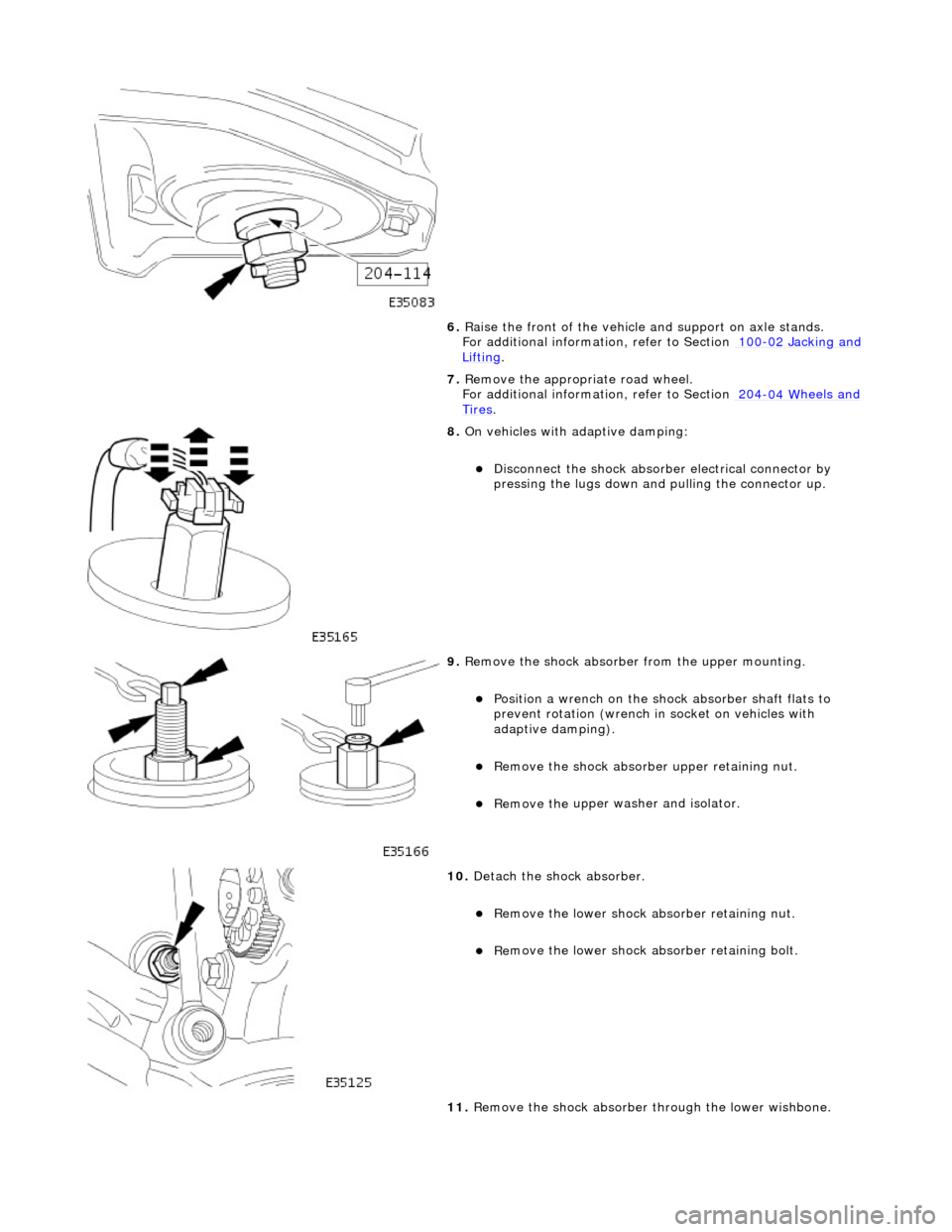
8. On
vehicles with adaptive damping:
Di
sc
onnect the shock absorber electrical connector by
pressing the lugs down and pulling the connector up.
9. Re
move the shock absorber from the upper mounting.
Posi
ti
on a wrench on the shock absorber shaft flats to
prevent rotation (wrench in socket on vehicles with
adaptive damping).
Re
move the shock absorber
upper retaining nut.
Remove the u
pper washer and isolator.
10 . De
tach the shock absorber.
R
e
move the lower shock ab
sorber retaining nut.
Re
move the lower shock ab
sorber retaining bolt.
11. Remove the shock absorber through the lower wishbone.
Page 107 of 2490
I
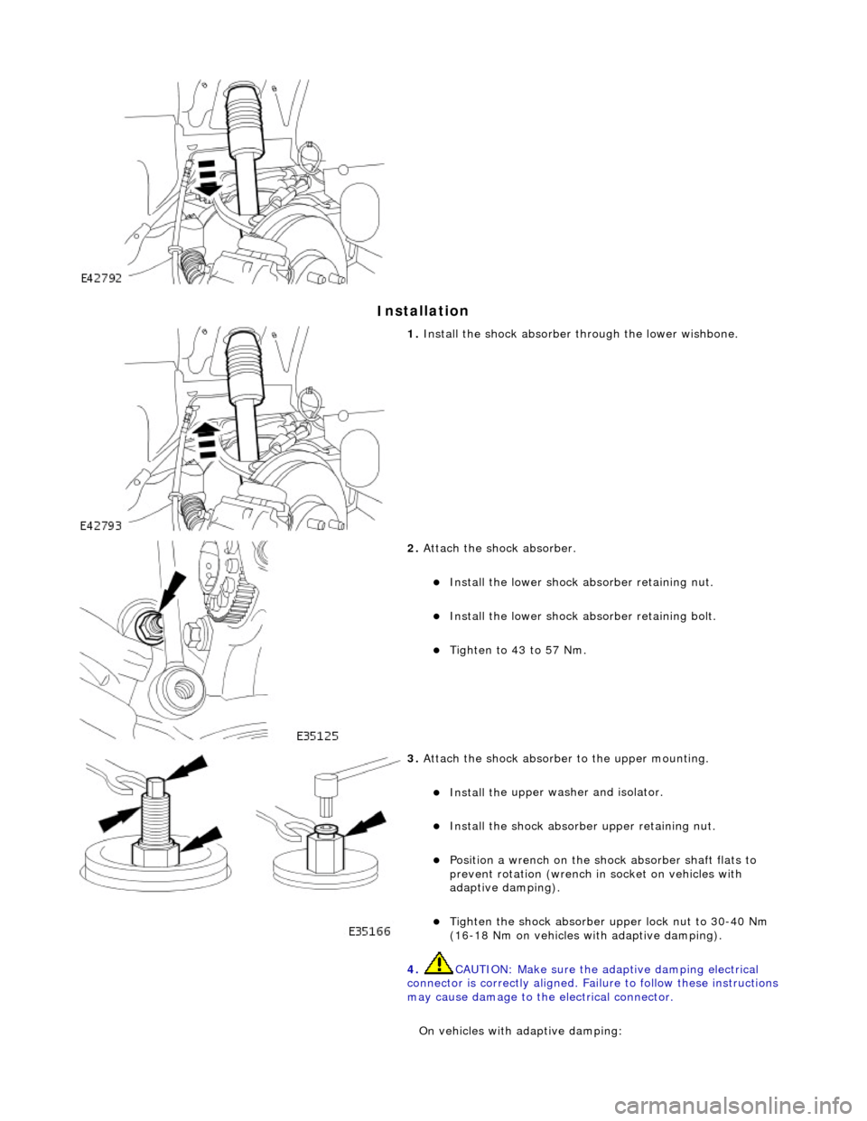
nstallation
1.
Install th
e shock absorber through the lower wishbone.
2. Att
ach the shock absorber.
Inst
all the lower shock ab
sorber retaining nut.
Ins
tall the lower shock absorber retaining bolt.
Ti
ghten to 43 to 57 Nm.
3. At
tach the shock absorber to the upper mounting.
Install th
e upper washer and isolator.
Inst
all the shock absorber upper retaining nut.
Posi
tion a wrench on the shock absorber shaft flats to
prevent rotation (wrench in socket on vehicles with
adaptive damping).
Tigh
ten the shock absorber upper lock nut to 30-40 Nm
(16-18 Nm on vehicles with adaptive damping).
4. CAUTION: Make sure the adaptive damping electrical
connector is correctly aligned. Failu re to follow these instructions
may cause damage to the electrical connector.
On vehicles with adaptive damping:
Page 108 of 2490
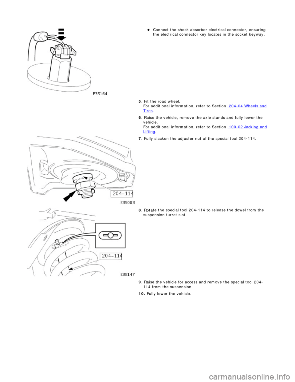
Connect
the shock absorber elec
trical connector, ensuring
the electrical connector key locates in the socket keyway.
5. Fit the road wheel.
For additional informat ion, refer to Section 204
-04 W
heels and
Tire
s.
6. Ra
ise the vehicle, remove the axle stands and fully lower the
vehicle.
For additional informat ion, refer to Section 100
-02
Jacking and
Liftin
g.
7. Ful l
y slacken the adjuster nut of the special tool 204-114.
8. Rot a
te the special tool 204-114 to release the dowel from the
suspension turret slot.
9. Raise the vehicle for access an d remove the special tool 204-
114 from the suspension.
10. Fully lower the vehicle.
Page 135 of 2490

Front Suspension - Front Wheel Bearing
Re
moval and Installation
S
pecial Tool(s)
Hub Remover
204-193 (JD 224)
Hub Removal Collets
2
04-194 (JD 225)
Hub Holdin
g Tool
204-195 (JD 227)
Hub Replacer
2
04-196 (JD 236)
Wh
eel Bearing Remover
204-197 (JD 237)
Wh
eel Bearing Replacer
204-198 (JD 238)
ABS Rotor Nut Socket
20
6-066A
Ci
rclip Pliers