abs JAGUAR X308 1998 2.G Owner's Manual
[x] Cancel search | Manufacturer: JAGUAR, Model Year: 1998, Model line: X308, Model: JAGUAR X308 1998 2.GPages: 2490, PDF Size: 69.81 MB
Page 141 of 2490

Front Susp
ension - Wheel Hub
Re
moval and Installation
S
pecial Tool(s)
Hub Remover
204-193 (JD 224)
Hub Removal Collets
2
04-194 (JD 225)
Hub Holdin
g Tool
204-195 (JD 227)
Hub Replacer
2
04-196 (JD 236)
Wh
eel Bearing Remover
204-197 (JD 237)
Wh
eel Bearing Replacer
204-198 (JD 238)
ABS Rotor Nut Socket
20
6-066A
Ci
rclip Pliers
Page 147 of 2490

Front Suspension - Wheel Knuckle
Re
moval and Installation
S
pecial Tool(s)
Hub Remover
204-193 (JD 224)
Hub Removal Collets
2
04-194 (JD 225)
Hub Holdin
g Tool
204-195 (JD 227)
Hub Replacer
2
04-196 (JD 236)
Wh
eel Bearing Remover
204-197 (JD 237)
Wh
eel Bearing Replacer
204-198 (JD 238)
ABS Rotor Nut Socket
20
6-066A
Ci
rclip Pliers
Page 166 of 2490

Rear Su
spension -
Lubric
ants, Fluids, Sealants and Adhesives
Torques
UnitSp
ecification
Loctite27
0
Greas eShell Retin a
x 'A'
Greas
eCastro l 'NT
R'
Com
p
onent
Nm
N
u
t - hub to axle shaft
3
04 -
336
Nu
t -
hub carrier pivot pin
88
-
118
Bol
t
- ABS sensor to hub carrier
8-1
0
Nu
t - stabilizer bar link to lower wishbone.
30
-40
Nu
t - stabilizer bar to link assembly.
30
-40
Bolts -
monostrut to body mounting brackets
88
-
118
Bolt
s
- monostrut to wishbone tie assembly
77
-
103
Bolts
- bu
mp stop to body
26
-34
Bol t
- damper lower mounting
80
-
100
N
u
t - damper top
31
-39
Bolts -
damper mounting plate to body
17
-23
Page 167 of 2490

Rear
Suspension - Rear Suspension
Description an
d Operation
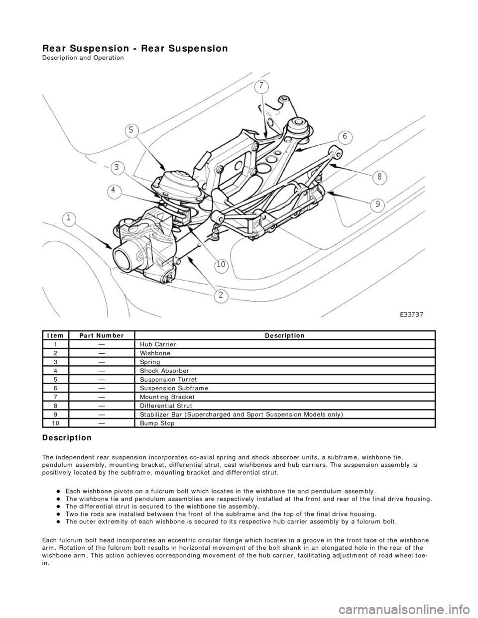
Description
The i
ndependent rear suspension incorporates co-axial sp
ring and shock absorber units, a subframe, wishbone tie,
pendulum assembly, mounting brac ket, differential strut, cast wishbones and hub carriers. The suspension assembly is
positively located by the subframe, mounting bracket and differential strut.
Each wi
shbone pivots on a fulcru
m bolt which locates in the wishbone tie and pendulum assembly.
The wish
bone tie and pendulum assemblies are respectively in
stalled at the front and rear of the final drive housing.
The differential
strut is secured to the wishbone tie assembly.
Two ti
e rods are installed between the front of the
subframe and the top of the final drive housing.
The ou
ter extremity of each wishbone
is secured to its respective hub carrier assembly by a fulcrum bolt.
Each fulcrum bolt head incorporates an ec centric circular flange which locates in a groove in the front face of the wishbone
arm. Rotation of the fulcrum bolt results in horizontal movement of the bolt shank in an elongated hole in the rear of the
wishbone arm. This acti on achieves corresponding movement of the hub carrier, facilita ting adjustment of road wheel toe-
in.
It
em
Par
t Number
De
scription
1—Hub Carrier
2—Wi
shbone
3—Sprin
g
4—Shock Absorber
5—Suspensi
on Turret
6—Suspensi
on Subframe
7—Moun
ting Bracket
8—D
ifferential Strut
9—Stabilizer Ba
r (Supercharged and
Sport Suspension Models only)
10—Bum
p Stop
Page 168 of 2490

Each r
oad spring and is located between the wishbone in
tegral spring seat and the body suspension turret.
Each shoc
k absorber unit is installed
co-axially within the road spring.
The lo
wer end of each shock absorber is secured to the
wishbone by a bolt which also functions as a pivot.
Adaptive damping is av
ailable as an option.
A
rear stabi
lizer bar is installed on
Supercharged and Sport Suspension models . Mounted at the rear of the wishbone
tie assembly, the stabilizer bar is connected to the wishbone by short links.
Op era
tion
As each road wheel r
i
ses, move
ment is transmitted through th e hub carrier assembly to the wishbone and axle shaft. The
corresponding rise of the wishbone compre sses the road spring and partially telescopes the shock absorber. During this
action, the spring absorbs result ing shocks and the shock absorber minimizes spring oscillation.
During cornering, vehicle weight is transferred to the outer road wheel with a resulting tendency for the inner wheel to lift.
On Supercharged and Sport Suspension vehicl es, a rear stabilizer bar assists in minimizing this tendency by transferring a
proportion of potential lift of the inner wheel to the outer wheel. This results in enhanced body stability with improved
cornering capabilities.
Page 172 of 2490

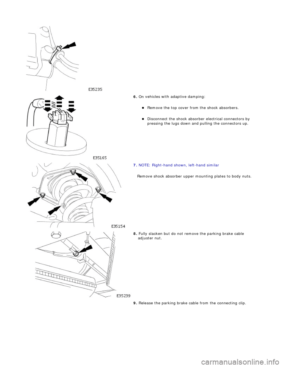
6. On
vehicles with adaptive damping:
R
e
move the top cover from
the shock absorbers.
Disc
onnect the shock absorber electrical connectors by
pressing the lugs down and pulling the connectors up.
7. NOTE : R
ight-hand shown, left-hand similar
Remove shock absorber upper mo unting plates to body nuts.
8. Fully slacken bu
t do not remove the parking brake cable
adjuster nut.
9. Release the parking brake cabl e from the connecting clip.
Page 178 of 2490

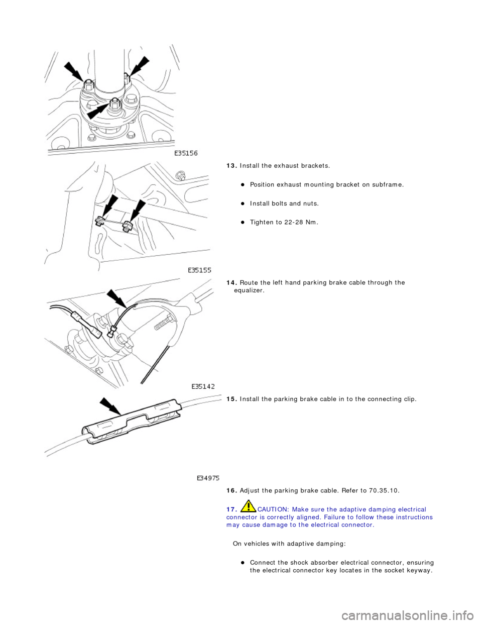
13. Inst
all the exhaust brackets.
Position exha
ust mounting bracket on subframe.
Inst
al
l bolts and nuts.
Tigh
te
n to 22-28 Nm.
14 . Route the
left hand parking brake cable through the
equalizer.
15 . Install th
e parking brake cable
in to the connecting clip.
16. Adjust the parking brake cable. Refer to 70.35.10.
17. CAUTION: Make sure the adaptive damping electrical
connector is correctly aligned. Failu re to follow these instructions
may cause damage to the electrical connector.
On vehicles with adaptive damping:
Conne ct
the shock absorber elec
trical connector, ensuring
the electrical connector key locates in the socket keyway.
Page 180 of 2490

Rear Su
spension - Rear Shock Absorber
Re
mo
val and Installation
Remov
a
l
S
p
ecial Tool(s)
Spri
ng C
ompressors
204-179 (JD 199)
Spri ng Re
taining straps
204-179-1 (JD 199-1)
1. CAUTION: Replacement of nuts and bolts: Various
thread-locking devices are used on nuts and bolts throughout the
vehicle. These devices restrict the number of times a nut or bolt
can be used.
For additional informat ion, refer to Section 100
-00
General
Informati
o
n
.
R a
ise the rear of the vehicle
and support on axle stands.
For additional informat ion, refer to Section 100
-02
Jacking and
Liftin
g.
2. Re
move the relevant rear wheel.
For additional informat ion, refer to Section 204
-04 W
heels and
Tire
s.
3. CAUTIO
N: Do not suspend the caliper from the brake
hose as this will damage the hose.
Remove the brake caliper from the carrier.
1. Remove the caliper spring clip.
2. Remove the guide pin dust caps.
3. Slacken and withdr aw the guide pins.
4. Remove the caliper from the carrier and secure to the suspension mounting bracket using a tie strap.
4. Disc
onnect the wheel speed sensor electrical connector.
Page 182 of 2490

Withdraw th
e hub carrier and support on a block of wood.
9. CAUTIO
N: Note the position of
the shims during removal.
They must be returned to th eir original position during
installation.
Noting their positions, remove the shim from each end of the
pivot pin sleeve.
10 . WAR
NINGS:
ENSURE THE SPECIAL TOOLS ARE POSITIONED
DIAMETRICALLY OPPOSITE ON THE SPRING AND THE ARMS ARE
CORRECTLY SEATED .
WHEN COMPRESSING THE SPRING, TIGHTEN THE
SPECIAL-TOOL ADJUSTMENT BOLTS EVENLY.
Compress the spring.
Install and alig n th
e special
tools 204-179 diametrically
opposite on the spring.
Eve n
ly tighten the special tool tensioning bolts to
compress the spring.
11 . R
emove the shock absorber to
wishbone mounting nut and
bolt.
12. Remove the nuts securing th e shock absorber and spring
upper mounting to the body.
Page 183 of 2490

13
.
Using the special tools 204-179-1, secure the upper mounting
to the spring.
14
.
Using a jack, retract the shock absorber through the
wishbone aperture.
15
.
Position a bolt through the spring coils and shock absorber
lower-bush, to temporarily locate the shock absorber.
16. Partially lower the jack for a ccess to the top of the shock
absorber.
17. On vehicles with adaptive damping:
Di
sconnect the shock absorber electrical connector by
pressing the lugs down and pulling the connector up.