abs JAGUAR X308 1998 2.G Workshop Manual
[x] Cancel search | Manufacturer: JAGUAR, Model Year: 1998, Model line: X308, Model: JAGUAR X308 1998 2.GPages: 2490, PDF Size: 69.81 MB
Page 3 of 2490

Rear Toe Adjustment (57.65. 08)
Whee
l
Bearing Circlip Inspection
Wheel Bearing Inspection
204‐01: Front Suspension
Specification
Description and Operation
Front Suspension
Removal and Installation
Ball Joint (60.15.02)
Rear Lower Arm (60.35.54)
Rear Lower Arm Bushing (60.35.56)
Front Shock Absorber (60.30.04)
Spring
Spring Seat (60.20.03)
Front Sta
bilizer Bar (60.10.01)
Front Stabilizer Bar Bushing (60.10.04)
Front Stabilizer Bar Link (60.10.02)
Upper Arm Bushing
Front Wheel Bearing (60.25.40)
Wheel Hub
Wheel Knuckle (60.25.23)
Wheel Knuckle and Wheel Hub Assembly (60.25.38.90)
Wheel Knuckle and Wheel Hub Assembly Conversion (60.25.43)
204‐02: Rear Suspension
Specif
ication
Description and Operation
Rear Suspension
Removal and Installation
Axle Bump Stop (64.30.15)
Rear Suspension and Axle Assembly (64.25.01)
Rear Shock Absorber (64.30.02)
Shock Absorber Lower Bushing (64.30.39)
Spring (64.20.01)
Rear Stabilizer Bar (64.35.08) ‐ 4.0L SC V8 ‐ AJ26
Rear Stabilizer Bar Bushing (64.35.18) ‐ 4.0L SC V8 ‐ AJ26
Page 7 of 2490

206‐07: Powe r Brake Actuation
Specif
ication
Description and Operation
Brake Booster
Removal and Installation
Brake Booster (70.50.17)
Brake Booster and Brake Master Cylinder (70.50.18)
206‐09: Anti ‐Lock Control
Specification
Description and Operation
Anti‐Lock Control
Diagnosis and Testing
Anti‐Lock Control
Removal and Installation
Anti‐Lock Brake System (ABS) Module (70.60.02)
Front Wheel Speed Sensor (70.60.03)
Hydraulic Cont
rol Unit (HCU)
Rear Wheel Speed Sensor (70.60.04)
Wheel Speed Sensor Ring (70.60.25)
211: Steering System
211‐00: Steering System ‐ General Information
Specification
Description and Operation
Steering System
Diagnosis and Testing
Steering Sy
stem
General Procedures
Power Steering System Filling and Bleeding
Power Steering System Flushing (57.15.08)
Power Steering System Vacuum Filling and Bleeding
Steering Gear Centralizing
Page 39 of 2490
Before inspecting a component for wear or per
forming a dimensional check,
ensure that it is absolutely clean; a slight smear
of grease can conceal an incipient failure. When a component is to be checked dimensionally against figures quoted for it,
use the correct equipment (surface plates, micrometers, dial gauges etc.) in serviceable condition. The use of makeshift
equipment can be dangerous. Reject a component if its dimensio ns are outside the limits quoted, or if damage is apparent.
A part may be refitted if its critical di mension is exactly to the limit size and it is otherwise satisfactory. Use Plastigauge 12
Type PG-1 for checking bearing surface clearance, e.g. big end bearing shell to crank jour nal. Instructions for the use of
Plastigauge and a scale giving bearing clearances in steps of 0.0025 mm (0.0001 in) are supplied with the package.
Safety
Precautions
• WAR
NINGS:
WORKING ON THE FUEL SYSTEM RESULTS IN FUEL AND FUEL VAPOUR BEING PRESENT IN THE ATMOSPHERE. FUEL
VAPOUR IS EXTREMELY FLAMMABLE, HENCE GREAT CARE MUST BE TAKEN WHILST WORKING ON THE FUEL SYSTEM.
ADHERE STRICTLY TO THE FOLLOWING PRECAUTIONS:
DO
NOT SMOKE IN THE WORK AREA.
DISP
LAY 'NO SMOKING' SIGNS AROUND THE AREA.
DISCONNECT TH
E BATTERY BEFORE WORKING ON THE FUEL SYSTEM.
DO NOT CONNEC
T/DISCONNECT ELECTRICAL CIRCUITS
, USE ELECTRICAL EQUIPMENT OR OTHER TOOLS OR
ENGAGE IN WORKING PRACTICES WHICH IN ANY WAY MAY RESULT IN THE PRODUCTION OF SPARKS.
ENS
URE THAT A CO2 FIRE EXTINGUISHER IS CLOSE AT HAND.
ENS
URE THAT DRY SAND IS AVAILABLE TO SOAK UP ANY FUEL SPILLAGE.
EMP
TY FUEL USING SUITABLE FIRE PROOF EQUIPMENT IN
TO AN AUTHORIZED EXPLOSION PROOF CONTAINER.
DO NOT EMP
TY FUEL WHILE WORKING IN A WORKSHOP OR A PIT.
ENS
URE THAT WORKING AREA IS WELL VENTILATED.
ENS
URE THAT ANY WORK ON THE FUEL SYSTEM IS ON
LY CARRIED OUT BY EXPERIENCED AND WELL QUALIFIED
MAINTENANCE PERSONNEL.
ENS
URE THAT FUME EXTRACTION EQUIPMENT IS USED WHERE APPROPRIATE.
FUME EXTRACTION EQUIPMENT MUST BE IN OPERATION WHEN SOLVENTS ARE USED E.G. TRICHLOROETHANE,
WHITE SPIRIT, SBP3, METHYLENE CHLORIDE, PERCHLORETHY LENE. DO NOT SMOKE IN THE VICINITY OF VOLATILE
DEGREASING AGENTS.
General workshop practices:
Disc
onnect the grounded termin
al of the vehicle battery.
D
o not apply heat in an attempt to free seized nuts or fitt
ings; as well as causing damage to protective coatings,
there is a risk of damage from stray heat to electronic equipment and brake lines.
Keep oils and solven
ts away from naked flames and other sour
ces of ignition.
Adhere str
ictly to handling and safety inst
ructions given on containers and labels.
E
nsure that a suitab
le form of fire extinguisher is conveniently located.
Wh
en using electrical tools and equipment, inspect the power
lead for damage and check that it is properly earthed.
D
o not leave tools, equipment, spilt oil etc. around the work area.
Working beneath a vehicle:
Wh
enever possible, use a ramp or
pit in preference to jacking.
Posit
ion chocks at the wheels as we
ll as applying the parking brake.
N
ever rely on a jack alone to support a
vehicle; use axle stands, or blocks care fully placed at the jacking points, to
provide a rigid location.
Ch
eck that any lifting equipment used has adeq
uate capacity and is fully serviceable.
Working on air conditioning systems:
D
o not disconnect any pipes of the refrigeration system
unless you are trained and instructed to do so; a refrigerant
is used which can cause blindness if allowed to come into contact with the eyes.
Health Protection
P
rolonged and repeated contact with mineral oil will result in the removal of natural oils from the skin, leading to dryness,
In
spection
Page 42 of 2490
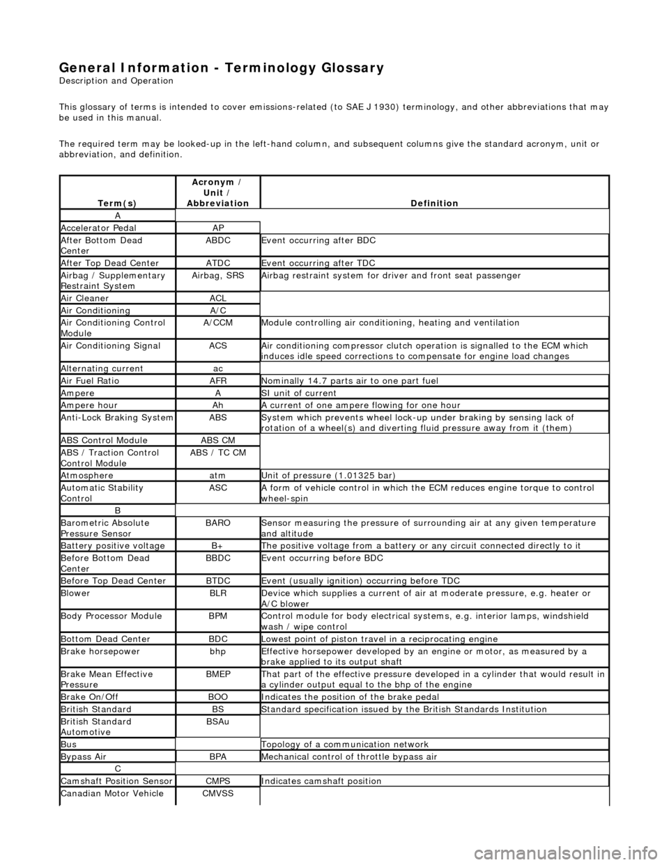
General Information - Terminology Glossary
Description an
d Operation
This glossary of terms is intended to cover emissions-related (to SAE J 1930) term inology, and other abbreviations that may
be used in this manual.
The required term may be looked-up in th e left-hand column, and subsequent columns give the standard acronym, unit or
abbreviation, and definition.
Te rm
(s)
Acr
ony
m /
Unit /
Abbreviation
De fi
nition
A
Accel
e
rator Pedal
AP
Af
ter Botto
m Dead
Center
ABDCEvent occurri ng after
BDC
Af
ter Top Dead CenterATDCEvent occurri ng after
TDC
Ai
rbag /
Supplementary
Restraint System
Airbag, SRSAi rbag restraint system for
dr
iver and front seat passenger
Air Cleane rACL
Air ConditioningA/C
Air Conditioning Con t
rol
Module
A/CCMModule c
ontrolling air conditioning, heating and ventilation
Air Conditioning SignalACSA
i
r conditioning compressor clutch operation is signalled to the ECM which
induces idle speed corrections to co mpensate for engine load changes
Alternating cu
rrent
ac
Ai
r Fuel R
atio
AFRN
omi
nally 14.7 parts air to one part fuel
Ampe
reASI unit of current
Ampere hourAhA current of one ampere
fl
owing for one hour
Anti-Lock Braking SystemABSS
y
stem which prevents wheel lock-up
under braking by sensing lack of
rotation of a wheel(s) and divertin g fluid pressure away from it (them)
ABS Control Mo
dule
ABS CM
ABS /
T
raction Control
Control Module
ABS / T
C CM
Atmosph
e
re
atmU
n
it of pressure (1.01325 bar)
Au
to
matic Stability
Control
ASCA form of vehicle
control
in which the ECM reduces en gine torque to control
wheel-spin
B
Baro me
tric Absolute
Pressure Sensor
BAR OSensor measuring the pressure of surr ou
nding air at any given temperature
and altitude
Bat t
ery positive voltage
B+The posi
ti
ve voltage from a battery or
any circuit connected directly to it
Before Bottom Dead
CenterBBDCEvent occurri ng before BD
C
Before Top Dead
Center
BTD
CEvent (usual ly
ignition) occurring before TDC
Blowe
rBLRDe
vice which supplies a current of air at
moderate pressure, e.g. heater or
A/C blower
Body Processor M
odule
BPMControl modu
le
for body electrical systems, e.g. interior lamps, windshield
wash / wipe control
Bott om D
ead Center
BD
CLowest poin t of piston
travel in a reciprocating engine
Brake hors
epowe
r
bhpEffecti
ve horsepower devel
oped by an
engine or motor, as measured by a
brake applied to its output shaft
Brake Mean Effective
Pres sureBME PThat p
art of the effective
pressure developed in a cyli nder that would result in
a cylinder output equal to the bhp of the engine
Brake On/ O
ff
BOOIn
dic
ates the position of the brake pedal
Br
it
ish Standard
BSStan
dar
d specification issued by the British Standards Institution
Br
it
ish Standard
Automotive
BSAu
BusTopology of a commu n
ication network
Bypass
AirBPAMechanica l
control of throttle bypass air
C
Camshaft Posit
i
on Sensor
CMPSIndi
cat
es camshaft position
Canadian Motor
V
ehicle
CMVSS
Page 44 of 2490
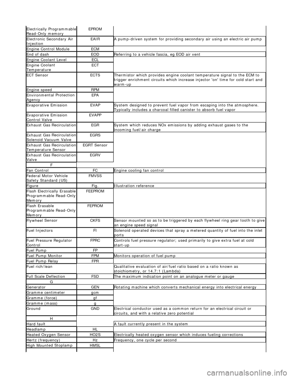
Electrically Programmable
R
ead-Only memory
EPROM
Ele
c
tronic Secondary Air
Injection
EAIRA p
ump-driven system for providing seco
ndary air using an electric air pump
Engine C
ontrol Module
ECM
End of dashEODR
e
ferring to a vehicle fascia, eg EOD air vent
Engine
C
oolant Level
ECL
Engine
C
oolant
Temperature
ECT
ECT Sen s
or
ECTSTherm
i
stor which provides engine coolant temperature signal to the ECM to
trigger enrichment circuits which increase injector 'on' time for cold start and
warm-up
Engine s
peed
RP
M
Environ m
ental Protection
Agency
EPA
Evaporative EmissionEVAPSy stem designed to prevent fu
el vapor from escaping into the atmosphere.
Typically includes a charcoal filled canister to absorb fuel vapor
Evaporative Emission
Control ValveEVAPP
Exhaust G
as Recirculation
EGRSys
t
em which reduces NOx emissions by adding exhaust gases to the
incoming fuel/air charge
Exhaus t G
as Recirculation
Solenoid Vacuum Valve
EGRS
Exhaus t G
as Recirculation
Temperature Sensor
EGRT Sen s
or
Exhaus
t G
as Recirculation
Valve
EGRV
F
F a
n Control
FCEngine
cooling fan control
F
e
deral Motor Vehicle
Safety Standard (US)
FMV S
S
Fi
gur
e
Fi
g.Illustrati
on reference
Flash
E
lectrically Erasable
Programmable Read-Only
Memory
FEE PR
OM
Flash
E
rasable
Programmable Read-Only
Memory
FEP R
OM
Flywhee
l
Sensor
CKFSSens
or moun
ted so as to be
triggered by each flywheel ring gear tooth to give
an engine speed signal
Fue l
Injectors
FISol
e
noid operated devices that spray a metered quantity of fuel into the inlet
ports
F u
el Pressure Regulator
Control
FP RCControls fuel pressure regu l
ator; used primarily to
give extra fuel at cold
start-up
Fue l
Pump
FP
Fue
l
Pump Monitor
FP
MMonitors operation of fuel pump
Fue l
Pump Relay
FP
R
Fu
el rich/lean
Q
u
alitative evaluation
of air/fuel ratio based on a ratio known as
stoichiometry, or 14.7:1 (Lambda)
F u
ll Scale Deflection
FSDTh
e
maximum indication point on
an analogue meter or gauge
G
Gene
rator
GENRot
a
ting machine which converts mechanical energy into electrical energy
G
r
amme centimeter
gcm
Gramm
e
(force)
gf
Gramm
e
(mass)
g
GroundGNDEle
c
trical conductor used
as a common return for an electrical circuit or
circuits, and with a relative zero potential
H
Hard f a
ult
A
fau
lt currently present in the system
HeadlampHL
Heat
ed Oxygen
Sensor
HO2SElectrically
h
eated oxygen sensor which induces fueling corrections
Hertz (frequency)HzFrequ
e
ncy, one cycle per second
High
Moun
ted Stoplamp
HMSL
Page 45 of 2490
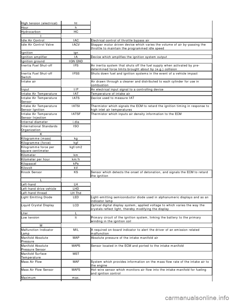
High
tension (electrical)
ht
Hourh
Hydro
carbon
HC
I
Idl
e Air Control
IACEl
ectrical control of throttle bypass air
Idl
e Air Control Valve
IACVStepper motor dri
ven device which vari
es the volume of air by-passing the
throttle to maintain the programmed idle speed
Ignitionign
Ignition am
plifier
IAD
evice which amplifies the i
gniti
on system output
Ignition groundIGN GND
In
ertia Fuel Shut-off
IFSAn
inertia system that shuts off the fuel supply when activated by pre-
determined force limits brough t about by (e.g.) collision
In
ertia Fuel Shut-off
Switch
IFSSShut
s down fuel and ignition systems in the event of a vehicle impact
Inta
ke air
Air drawn t
hrough a cleaner and distri
buted to each cylinder for use in
combustion
InputI/PAn
electrical input signal to a controlling device
Inta
ke Air Temperature
IATTem
perature of intake air
Inta
ke Air Temperature
Sensor
IATSDe
vice used to measure IAT
Inta
ke Air Temperature
Sensor Ignition
IATSITherm
istor which signals the ECM to retard
the ignition timing in response to
high inlet air temperatures
Inta
ke Air Temperature
Sensor Injection
IATSFTher
mistor which inputs air density information to the ECM
Internal diameteri.
dia
Inte
rnational Standards
Organization
ISO
K
Kilogramme (mass)kg
Kilogram
me (force)
kg
f
Ki
logramme force per
square centimeter
kg
f/cm2
Kilom
eter
km
Ki
lometer per hour
km
/h
Kilopasc
al
kP
a
KilovoltkV
Knock
Sensor
KSSens
or which detects the onset of detonation, and signals the ECM to retard
the ignition
L
Le
ft-hand
LH
Left-hand drive veh
icle
LHD
Le
ft-hand thread
LH Thd
Ligh
t Emitting Diode
LEDLigh
t-emitting semiconductor diode used
in alphanumeric displays and as an
indicator lamp
Liqu
id Crystal Display
LCDOp
tical digital display system, applied voltage to which varies the way the
crystals reflect light, thereby modifying the display
LiterL
Low ten
sion
ltPrim
ary circuit of the ignition system, linking the battery to the primary
winding in the ignition coil
M
Malfu
nction Indicator
Lamp
MILA
required on-board indicator to aler
t the driver of an emission related
malfunction
Mani
fold Absolute
Pressure
MAPAbsolute pressure o
f the intake manifold air
Mani
fold Absolute
Pressure Sensor
MAPSSensor loca
ted in the ECM and
ported to the intake manifold
Manifol
d Surface
Temperature
MST
Mass Ai
r Flow
MAFSy
stem which provides inform
ation on the mass flow rate of the intake air to
the engine
Mass Ai
r Flow Sensor
MAFSHot-wi
re sensor which monitors air flow
into the intake manifold for fueling
and ignition control
Maxim
um
max.
Page 47 of 2490
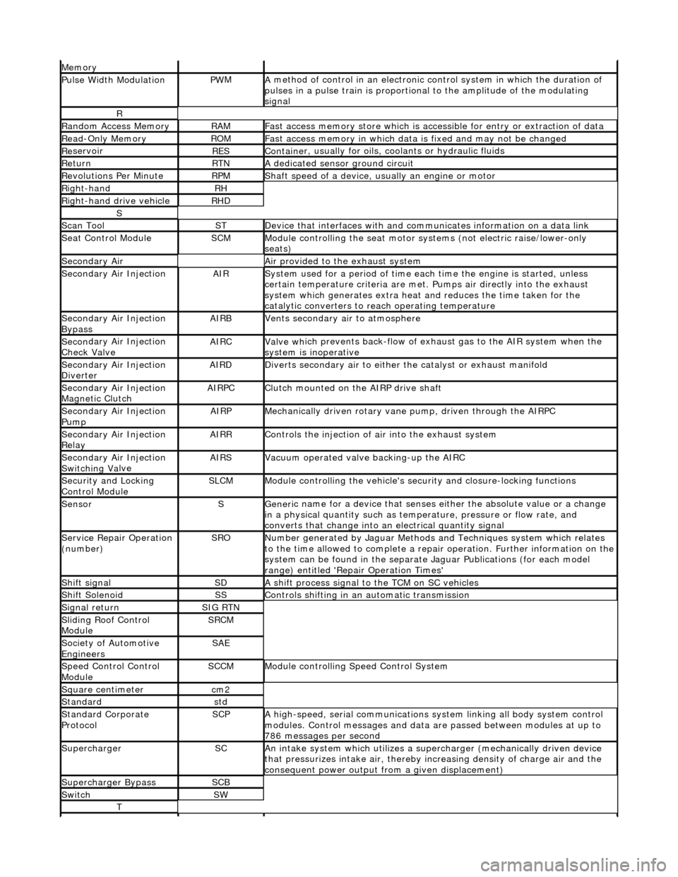
Mem
ory
Pulse Width ModulationPW
M
A
method of control in an electronic co
ntrol system in which the duration of
pulses in a pulse train is proportional to the amplitude of the modulating
signal
R
Ran
dom Access Memory
RAMF
ast access memory store which is accessible for entry or extraction of data
Re
ad-Only Memory
RO
M
F
ast access memory in which data
is fixed and may not be changed
Re
servoir
RESContaine
r, usually for oils,
coolants or hydraulic fluids
Re
turn
RTNA
dedicated sensor ground circuit
R
evolutions Per Minute
RP
M
Shaft speed o
f a device, us
ually an engine or motor
R
ight-hand
RH
Right-hand drive veh
icle
RHD
S
Scan T
ool
STDe
vice that interfaces with and comm
unicates information on a data link
Se
at Control Module
SCMModule
controlling the seat motor systems (not electric raise/lower-only
seats)
Secon
dary Air
Air pro
vided to the exhaust system
Secon
dary Air Injection
AIRSy
stem used for a period of time each
time the engine is started, unless
certain temperature criter ia are met. Pumps air directly into the exhaust
system which generates extra heat and reduces the time taken for the
catalytic converters to reach operating temperature
Secon
dary Air Injection
Bypass
AIRBVents secon
dary air to atmosphere
Secon
dary Air Injection
Check Valve
AIRCValve wh
ich prevents back-flow of exhaust gas to the AIR system when the
system is inoperative
Secon
dary Air Injection
Diverter
AIRDD
iverts secondary air to either
the catalyst or exhaust manifold
Secon
dary Air Injection
Magnetic Clutch
AIRP
C
Clu
tch mounted on the AIRP drive shaft
Secon
dary Air Injection
Pump
AIRPMe
chanically driven rotary vane
pump, driven through the AIRPC
Secon
dary Air Injection
Relay
AIRRCont
rols the injection of air into the exhaust system
Secon
dary Air Injection
Switchin
g Va
lve
AIRSV
acuum operated valve backing-up the AIRC
Secu
rity and Locking
Control Module
SLCMModul
e controlling the vehicle's security and closure-locking functions
SensorSGeneri
c name for a device
that senses either the absolute value or a change
in a physical quantity su ch as temperature, pressure or flow rate, and
converts that change into an electrical quantity signal
Servic
e Repair Operation
(number)
SRONu
mber generated by Jaguar Methods
and Techniques system which relates
to the time allowed to complete a repair operation. Further information on the
system can be found in the separate Jaguar Publications (for each model
range) entitled 'Repair Operation Times'
Shif
t signal
SDA
shift process signal to the TCM on SC vehicles
Shif
t Solenoid
SSControls shi
fting in an automatic transmission
Si
gnal return
SIG RTN
Slidin
g Roof Control
Module
SRCM
Society of Automotive
Engineers
SAE
Speed
Control Control
Module
SCCMModule con
trolling Speed Control System
Square c
entimeter
cm
2
Stan
dard
std
Stan
dard Corporate
Protocol
SCPA
high-speed, serial communications system linking all body system control
modules. Control messages and data ar e passed between modules at up to
786 messages per second
SuperchargerSCAn in
take system which utilizes a supercharger (mechanically driven device
that pressurizes intake air, thereby in creasing density of charge air and the
consequent power output from a given displacement)
Supercharger
Bypass
SCB
SwitchSW
T
Page 67 of 2490
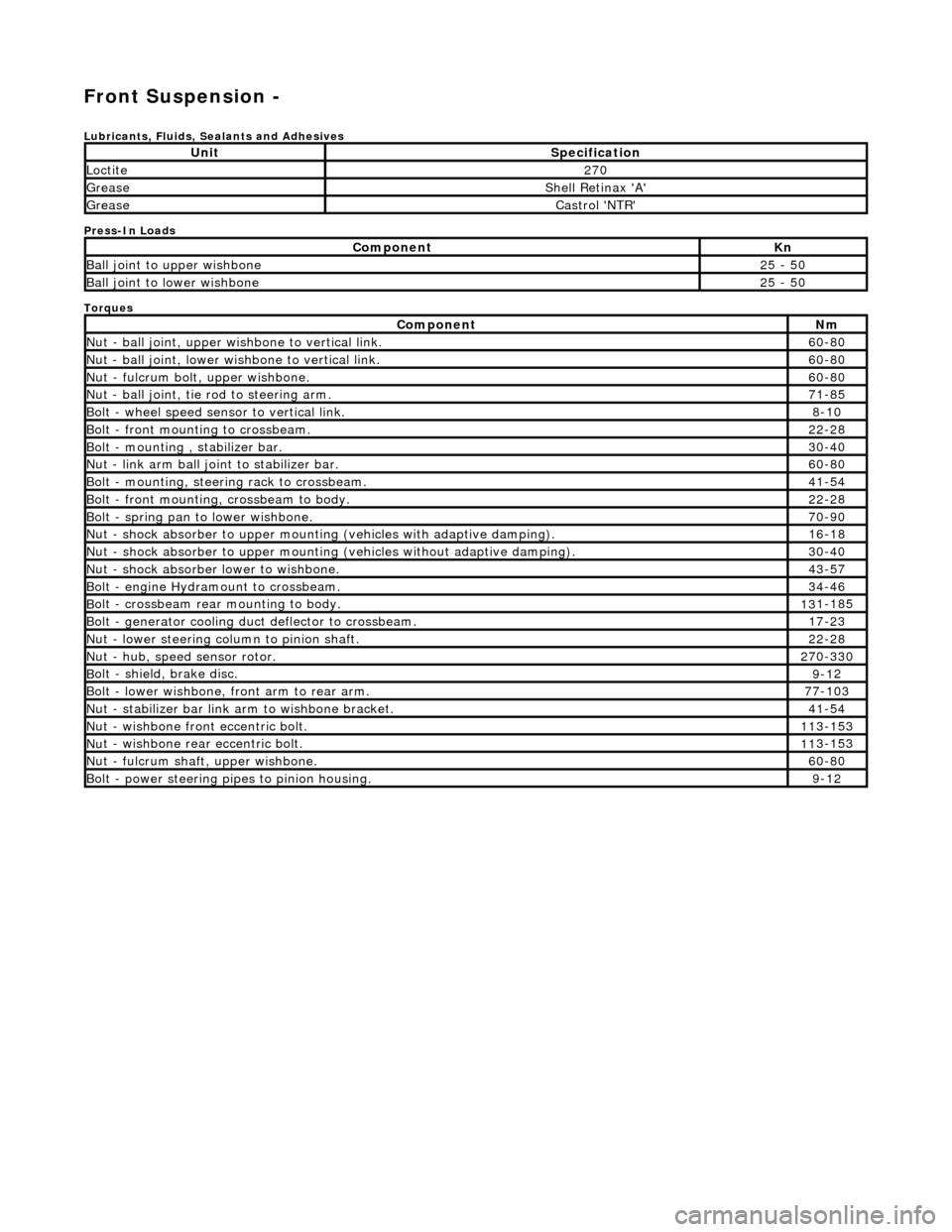
Front Suspension -
Lubri
cants, Fluids, Sealants and Adhesives
Press-In Loads
Torques
UnitS
pecification
Loctite27
0
Greas
e
Shell Retin
ax 'A'
Greas
e
Castro
l 'NTR'
Com
ponent
Kn
Ball join
t to upper wishbone
25
- 50
B
all joint to lower wishbone
25
- 50
Com
ponent
Nm
N
ut - ball joint, upper wishbone to vertical link.
60
-80
N
ut - ball joint, lower wishbone to vertical link.
60
-80
Nu
t - fulcrum bolt, upper wishbone.
60
-80
N
ut - ball joint, tie rod to steering arm.
71
-85
Bol
t - wheel speed sensor to vertical link.
8-1
0
Bol
t - front mounting to crossbeam.
22
-28
Bolt
- mounting , stabilizer bar.
30
-40
N
ut - link arm ball joint to stabilizer bar.
60
-80
Bolt
- mounting, steering rack to crossbeam.
41
-54
B
olt - front mounting, crossbeam to body.
22
-28
Bol
t - spring pan to lower wishbone.
70
-90
N
ut - shock absorber to upper mounting
(vehicles with adaptive damping).
16
-18
Nu
t - shock absorber to upper mounting (vehicles without adaptive damping).
30
-40
N
ut - shock absorber lower to wishbone.
43
-57
B
olt - engine Hydramount to crossbeam.
34
-46
B
olt - crossbeam rear mounting to body.
13
1-185
Bol
t - generator cooling du
ct deflector to crossbeam.
17
-23
N
ut - lower steering column to pinion shaft.
22
-28
N
ut - hub, speed sensor rotor.
27
0-330
B
olt - shield, brake disc.
9-1
2
Bol
t - lower wishbone, front arm to rear arm.
77
-103
Nu
t - stabilizer bar link arm to wishbone bracket.
41
-54
N
ut - wishbone front
eccentric bolt.
11
3-153
Nu
t - wishbone rear
eccentric bolt.
11
3-153
N
ut - fulcrum shaft, upper wishbone.
60
-80
Bolt -
power steering pi
pes to pinion housing.
9-1
2
Page 68 of 2490
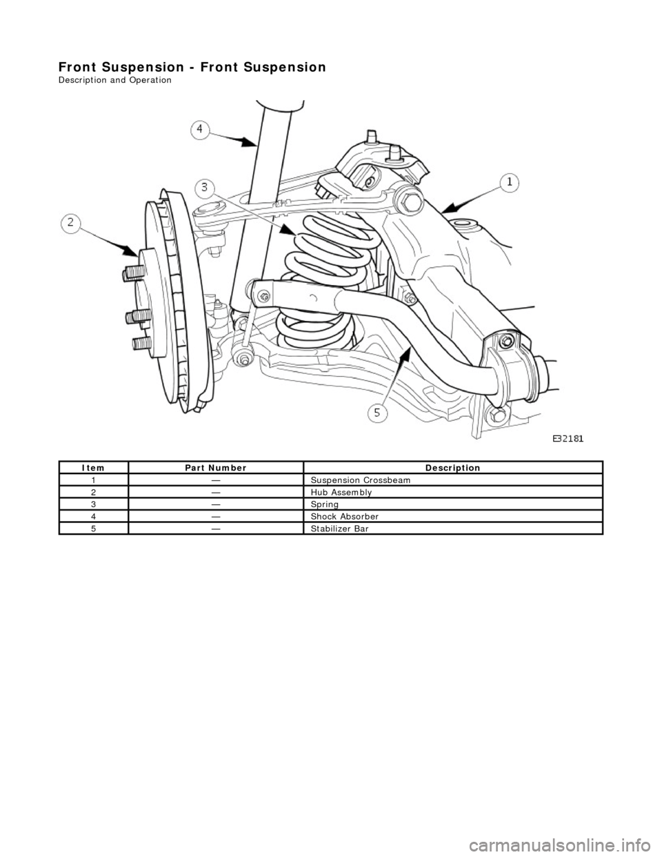
Front Suspension - Front Suspension
Description and Operation
Ite
m
Par
t
Number
De
scr
iption
1—Suspensi
on C
rossbeam
2—Hub Assembly
3—Sprin
g
4—Shock Absorber
5—St
abil
izer Bar
Page 69 of 2490
Front C
rossbeam
A
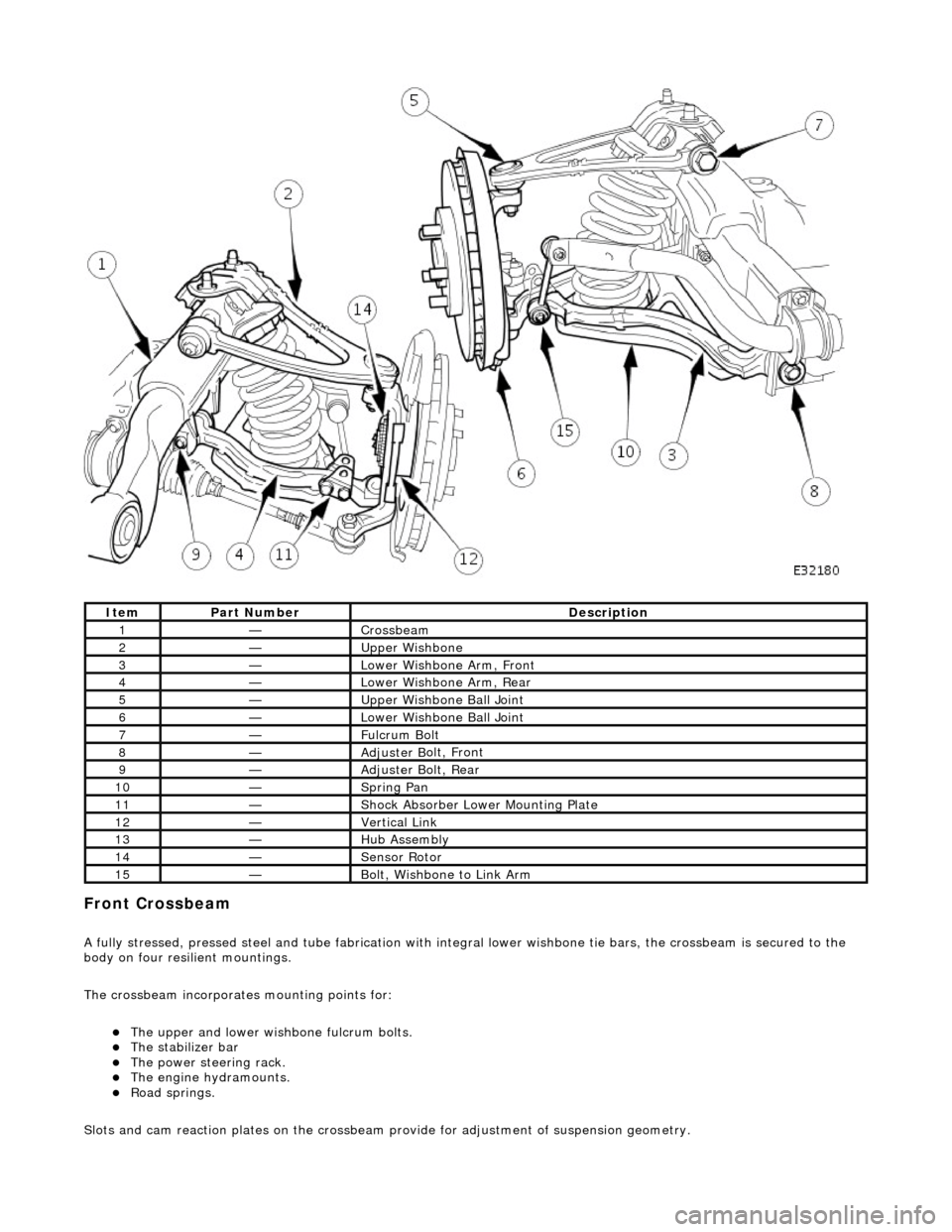
fully stressed, pressed steel and tube fa
brication with integral lower wishbone tie bars, the crossbeam is secured to the
body on four resilient mountings.
The crossbeam incorporates mounting points for:
The u
pper and lower wish
bone fulcrum bolts.
The
stabilizer bar
The power steering rack. The engine h
ydramounts.
R
oad springs.
Slots and cam reaction pl ates on the crossbeam provide for ad justment of suspension geometry.
It
em
Par
t Number
De
scription
1—Cro
ssbeam
2—Upper
Wishbone
3—Lower Wi
shbone Arm, Front
4—Lower Wi
shbone Arm, Rear
5—Upper
Wishbone Ball Joint
6—Lower Wi
shbone Ball Joint
7—Ful
crum Bolt
8—Adjuster B
olt, Front
9—Adjuster B
olt, Rear
10—S
pring Pan
11—Shock Absorber Lower M
ounting Plate
12—Vertical Link
13—Hub Assembly
14—Sensor R
otor
15—B
olt, Wishbone to Link Arm